Digital Electronics -- Flip-Flops

HTML-код
- Опубликовано: 25 июл 2013
- This video will discuss Flip-Flops. I will cover the following topics:
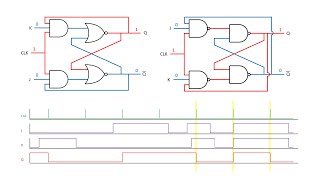
Cross Coupled NOR and NAND SR Flip-Flops Truth Tables
SR Flip-Flop Timing Diagram
Gated SR Flip-Flops Truth Table
Gated SR Flip-Flop Timing Diagram
Asynchronous SR Flip-Flop
Asynchronous SR Flip-Flop Timing Diagram
Positive Edge Trigger
Negative Edge Trigger
D Type Flip-Flop Truth Table
D Type Flip-Flop Timing Diagram
Asynchronous D Type Flip-Flop Truth Table
Asynchronous D Type Flip-Flop Timing Diagram
JK Flip-Flop Truth Tables
JK Flip-Flop Timing Diagram
Asynchronous JK Flip-Flop Truth Table
Asynchronous JK Flip-Flop Timing Diagram
You will find some other helpful items below:
Lecture notes: grace.bluegrass.kctcs.edu/~kd...
To help you take your notes: grace.bluegrass.kctcs.edu/~kd...
Handouts and Practice
grace.bluegrass.kctcs.edu/~kd...
grace.bluegrass.kctcs.edu/~kd...
Please leave a comment and 'like' the video if it was helpful.


I was trying to learn this stuff via Indian lectures, but just can't get used to their accent and I lose my focus often.
This is concise and well executed, thank you!
Glad to hear it was helpful.
I have the same problem, they are good but the accent ruins everything.
I've been watching a few videos and read A LOT and never got the hang of it, and now I finally do! Thank you, you're a lifesaver! :D
+Barak Levy That is awesome! I really appreciate it!!
Thank you soo much for this video. I was lost in class and this really cleared it up for me. Great Video.
Thank you very much for this helpful video. Now I understand. You saved my exam :)
Thank you so much for explaining everything visually and going through everything step-by-step. This video has helped me so much. Thank you!
Thank you very much for watching!
Great tutorial! Thank you. Showing how it works in the timing diagram and explained it well makes it so easy to understand.
Thank you.
Thank you so much. Your tutorial has helped me learn a lot. I'll have to watch again to pick up some more points. Well explained. You have given me more confidence that I can get through digital books.
+Peter Grierson Thank you very much!
Excellent work, very informative. You did an awesome job explaining step by step and provided plethora examples to cover every possible questions we may encounter!
Thanks! It means a lot.
Amaaaaazing, Now i love Flip flops they were pretty difficult for me to absorb before.!!
Seriously..Thanks in a million Professor :)
+Safa Fituri Glad I could help. Makes it worth the time!!
Yet again you've saved me from hours of reading! Thank you so much Sir, your lectures are amazing.
Glad to help.
Awesome video ! This really helped me to better understand my engineering lesson on pulse processing circuits. And using a highlighter is a great idea it helps a lot . Thank you so much!
Thanks!
Dude. Why couldn't my lecturer explain this so clearly?! The whole time it felt like there was some mysterious secret to it we weren't being let in on, but it's really straight forward and logical, thank you.
Thanks! Appreciate the comment! Good luck with your classes.
@con ty Glad to help!
Thank you so much!!!
I have been studying for 7 hours straight! and I finally understand the part about flip flops!
I need to go to school in about 6 hours from now and make my test....
you really saved me on this one :D
+Honeyroasted cashewnuts Glad I could help. Good luck on the test!
yes!!! I passed! this really helped, it was the only part of the whole exam I actually understood properly! I can't thank you enough!
You are absolutely great explaining all this, now I understand, greatly appreciated.
Thank you!!
wow...love the way u explained.. everything was so crystal clear.. thanks..
Jesus Bless you man
Thanks! Hope it helps.
Thank you SO MUCH! My final exam is tomorrow, and this is on the exam, but my teacher never actually taught it. If it hadn't been for this, I wouldn't have had any clue how to do it on the exam. THANK YOU!!!
Thank you very much. Good luck on the exam!!
@Adelfaye Cayasan the SR flip Flop has an invalid state when both inputs are active. The JK flip flop has a toggle mode when both are activated. That is the main difference.
***** There are no XNOR gates in the Flip-Flops video. What time in the video are you referring to? Maybe they were NOT gates.
***** Yes, they still have 2 inputs. One just comes from the output of the other. It is called a cross-coupled NOR (or NAND) SR flip-flop. It must be hooked up in this way to operate as a flip-flop.
***** For the "real" circuit to work you would have the S and R inputs tied to something. A button, sensor, clock, whatever. For me to show you how you can find the outputs, I just gave you the 1 and 0 inputs as needed. Everything is in the video.
I never make comments on RUclips but I made an exception for this exceptional video. Thanks a lot. Watched it a day before my exams and I passed...had no prior info about the topic. Thanks.
Sorry I am just seeing this. Congrats on the exam. Glad I could help.
Awesome Video! I haven't ever seen flip flops explained this clearly!
Thank you!
i spent days trying to understand this from another video but when i listen to this video thank god i under stand man you are the best thank you very much and like
Thanks!
Your videos are great. Thank you for taking the time to make them and help people like myself.
Thank you very much!
Superp!, Trying to figure out latches and flip-flops almost whole day now and this video is most helpful, thank you sir!
Glad I could help!
i owe lot to this video maker.
Man, why aren't u in my country? I would have made u my personal teacher! thank you so much, subscribed.to ur channel, please don't stop making such wonderful clear videos, I love your way of explanation! thanks
+Justin Cruiz Thanks!!
you just got another subscriber, excellent lecture and very clear explanation! thanks you very much
Thank you!!
Don't stop what your doing! You helped a lot! Thanks
Thank you.
Thanks a lot sir. The lesson was really useful. :)
Subscribing to your channel :) :)
Today I'm gonna bring the knowledge that I get from you to teach my friends because we're having a Digital Logic exam tomorrow. THANK YOU SO MUCH FOR ALL I REALLY APPRECIATE THIS .
Could I get a bless from you ? If you don't mind :)
Good luck with the exam!
That's mean a lot to me. :) I've showed them your video and I'm absolutely sure that this will help and now one of my friends are opening your shift register video !!! A Lot Of thank you again from university student in Thailand I wish you would be our teacher or Professor !!!
noonice60 Thanks. I appreciate that.
Awesome, once more you are saving me...exam on Sunday, will let you know if I passed thanks to your videos! :)
Best of luck on the test.
that was really good , I appreciate your work
thanks a lot :)
+Safwan Algaidi Thank you very much!
Can't say thanks enough. I've watched this video about 7 times now, but I really understand it in full now. However I do have one question. When dealing with the J K FF can both Sd and Rd go low? I know they override whatever is
Very good tutorials my friend, you are hot on passing knowledge to others. keep it up
Thank you!!
My tuition money should go to you. Textbook (Terribly written with just 1 example of each situation) + Having trouble understanding professor = F on the test.
Thank you very much!! Best of luck on your future exams.
KimichiSushi
Thanks! Excellent review!
best explanation of flip flops I have ever witnessed
+Avi Bansal Thank you.
Thank you very much!! Really appreciated. Learnt a lot about the diagrams. Do you have any videos explaining the way you get the various conditions using the gates like in the first example?
Thanks! Not sure what you mean about getting the conditions. For my examples, I am just making the inputs up. They could be from anything from a sensor to a simple switch. Please clarify if that does not answer your question.
After watching this I realized I failed my test. But I'm so grateful to know why I failed it. Great video!!!
Sorry to hear about the test. Keep at it.
hey @movieHQ, at 35:18 you are saying you highlight your negative edges? I might be wrong but shouldn't i be the positive edges?
Awesome videos!
Yes. I said negative, but I am actually highlighting the positive. So the answer is correct.
brilliantly explained! thanks!
+Vinay Adithya thanks.
thank you. aside from yours do you have an other learning resource recommendations? my goal if it matters is simply but not simply full on tech expert
+Elon Ambrose No, honestly I don't. I am working on a basic electronics series now. Should be out in a few weeks.
Great video! Quick side-question though, when an asynchronous JK flip flop is active low on Preset and Clear, does that mean that the J and K inputs are inactive while Pre and Clear are high? Appreciate the help.
ntalehxc No. If Preset and Clear are active low, when one goes low it disables the JK inputs. If Pre/Clr are high, then JK operate normally.
Thanks for watching.
Really great video, very good explanation ! Thank you !
I appreciate it.
Best explanation.Clean and detailed .
Thanks!
This video was REALLY helpful! Thanks!!!
No problem. Glad it helped.
Very clear and helpful.Thank you very much !
Thanks!
very good videos, keep it up.
thanks
Thanks for watching.
Thx a lot
So helpful it's help me to understand it for the exam
Many thx and i hope you make more videos for programming or any things for engineering
Thank you for watching!!
I would like it 100 times if I could. Thanks so much for this video.
Thank you very much!!
thank u so much sir,,,,,,,,,,,incredible explanation,,,,,,, do continue to share the knowledge,,,,,,,, 5 stars rating
Thanks!!
MovieHQ
at 19:00 minutes into the video, how the Q output waveform is displayed confused me. it's not how it is according to the truth table or am i missing something? according to the truth table, wouldn't a HIGH Set and a LOW Reset cause the Q output to be a LOW?
Yes it would. That is what is on the Q output in the video. Not sure what you are seeing that is different from that.
BEST VIDEO I EVER SEE PLEASE PLEASE DO NOT STOP TO PUT THE NEW VIDEO GREAT JOB EXCELLENT EXPLANATION FOR 35 MIN GOOD LUCK FOR ALL JOB
Thanks
Amazingly helpful video XD
Thanks! Glad to help.
Great tutorial, Thanks!
Yichi Zhang You are welcome. And thanks for watching!
I love to wear flip flops especially in the summer time very soft.
😂
it's really great. sir....keep up the good work sir
Thank you.
Really really good explanation, keep it up please :)
Thank you!
Were the last few J-K flip flops active low? I was a little confused when I seen the highlighted areas was low and it caused a reset...
They were positive edge triggered. JKs do not usually use the entire pulse but only the positive going or negative going edge of the clock.
This was awesome,, I'm going to draw out the actual gates and write notes, but I understand these ,, it was a come 2 jesus moment lol
Thanks.
thank you very very very much for the amazing video and the amazing explanation.
Thanks for watching and the comment!!
Also, do you have any practice problems online anywhere ?
Thank you your videos are helpful
I have test reviews you are more than welcome to look through.
district.bluegrass.kctcs.edu/kevin.dunn/files/Reviews/
Is the enabler the same as the clock pulse? We never used enables in class for flip flops. If they're not the same wouldnt the time diagram be different?. I noticed that when there's a change while the enable is HIGH, you change it, but the way we did it is we would wait until the NEXT clock pulse before doing any changes despite what changes in the input. What happens at the beginning of the clock pulse stays until the next clock pulse.
Am I getting it right? I'm confused. I have a quiz in two days :s
Ok never mind I didn't realize you explained it later on. I was too quick to post this.
Thanks a lot for this video!
prepareuranus Glad you got it. Thanks for watching!!
Thank you Sir!
That was really clear.
Thank you!
Very well done! Thank you
You are welcome.
can a invalid mode be possible if the S.R FLIP FLOP inputs are all lows and the outputs are all high? for the NOR FLIP FLOP
The only time you will have an invalid condition (both output the same) would be if you activate BOTH S and R.
thank you for great tutorial, I understood now.
+Mai Điệp You are welcome!!
Sorry for asking. but what if both SD and Rd are at low state simultaneously? and u said that the clock is put to enable the ff by 2 AND gates in the level trigger circuits, but any idea how a edge trigger ff is built? is edge trigger one built with logic gates or any other kind of circuits at the input of ff?? and what about low level triggered ff, does it use a XOR gate to achieve low level triggering? ( sorry to ask the last one though it's out of what u explained in this video) Thanks!
+Justin Cruiz I could not find a good diagram of what is inside a JK flip flop (found master-slave type but not edge trigger) If you make SD and RD both low, your output is determined by what is inside the ship. You would general develop a circuit to make sure they do not both go low.
The LOW level trigger is a master slave. I do not cover those in my classes.
I really appreciate your help. Thank you so much
+Tanmoy Sinha Roy You are welcome. Thanks for watching!
Where do the outputs Q and not Q go besides logic gates? and to store a bit means looping the signal inside? and power to store a bit go from connected transistors inside nor gates?
They are just outputs so they can go anywhere from other flip-flops, logic gates, displays, transistors, microprocessors, etc.
i wish you were my proffesor !! thanks !!
p.s. About asynchronous flip flops , when both low the output is undefined ?
+Haki Terror Thank you. It depends on the flip-flop. Yes, for an SR flip-flop it will be undetermined. For JK it will toggle.
Great video Thank you.
Thank you for watching!
this is the best instruction ever!!!!! thank you.....holy shit...
Thank you very much!!
thank you so much. I understood preparing for my exam :)
You are welcome.
I think jake Lary below was asking about this (maybe not) regardless I'm still unclear at 3:30 into the video.
If you have a 0 for the S and 0 for the R, how can you possibly determine the output of either of the NOR gates since each other input pin is coupled to the other gates output pin? I get if either S or R input was a 1, you'd know the NOR gates' output would be a 1 (then inverted to a 0) that makes sense, however I'm failing to see how you determined the output of the NOR gates.
Was it because the original S input state was set to 1, THEN you flipped it thus retaining the existing output value from the original R's output (which in turn fed a 1 into the S's other input - generating the 1 inverted to a 0)?
Is the S and R simultaneously set to 0 an invalid condition?
Please excuse my ignorance.
You got it. If I were to place S and R at 0 from the start, I would have no true idea of what it is holding. If I place a 1 on either S or R at the start, I can get something set/reset and then hold that. S and R can be both set to 0 (hold) but they CANNOT both be given a 1 as that is invalid.
Flip flops takes previous inputs into consideration (as it is sequential circuit ) so you can assume output of Q and Q' and then try taking S and R 0 0 and it'll give hold condition.
P.S. : great lecture sir HATS OFF. THANKS A LOT ! ! !
The website for lecture notes is not opening. I have tried it before but the same error occured
@3:30when you start with a low, how come you have those 1's before the nor gate. same thing with the second one but you have 0s because when you start with 0 and go through the Nor gate it should change to 1? not 0?
I am not 100% sure I know what you mean, but if you are referring to the other input, those are the binary values being fed back from the other gate's output.
If you are talking about the 1 and zero to the left of the bubble, those are just to say if it were an OR gate it would give that output, then inverts to... Does that help?
awesomely superb sir
Thanks!
at about time 5:15 when u have a LOW on set and a HIGH on reset, is that like erasing whatever data was stored in memory ?
It is resetting the Q output to a 0. Not really erasing. You may have wanted a 0 in there.
Te best channel in youtube!!
What is the difference
1) SCR vs D latch ?
2) LATCHES VS fLIP-FLOPS?
3)SYCHRONOUS VS Asychronous circuits?
i will appreciate your answer thanks...
Thanks! AN SCR is more of an analog device that acts similar to a voltage controlled switch. Latches are digital and latch, or hold, a single binary state until changed again. Latches can basically change any time while FF need an enable signal of some sort. Synchronous depends on if you are talking about inputs or the circuit. When talking about inputs, sync inputs are those that work with the clock (J, K, S, R, and D) while your Sd and Rd work independent of the clock and can change the outputs async (anytime). For the clock/circuit, Sync means all the clocks are tied together and pulsed at the same time. Async means the first one is tied to the clock which the remaining ones are fed from the previous output. Hope that helps some.
GOD bless you!!
Also for NAND truth table isnt s and r noted?
I may be stubborn but I am convinced that an SR flip flop is best when made with an OR gate , an AND gate and an Inverter. The AND gate output feeds one of the OR gate inputs, and is the Q flop output. The other OR gate input is the SR flip flop Set input. The OR gate output goes to one of the AND gate inputs. The other AND gate input is fed by an inverter output. The inverter input is the SR flip flop Reset input. There are no disallowed states and it is useful for creating Toggle flip flops (although it could use quite a few components as compared to what you are getting at) (is my only guess). If you need a Q not output add another inverter to the Q output.
That does indeed work. It is just not the historically correct SR flip-flop. In reality there is very little use for an SR except to build upon to make better gates. There are 2 disadvantages to your circuit. One is the increase in the number or parts and wiring between them and the second is the addition of a bit of delay. Not much but a bit. I am not an engineer so I am sure there is a reason this design is not used in "production".
@@MovieHQ The objective is not to make better gates but to make flip flop counters (for example) that do not require being reset first. All outputs can be known first and they are easy to understand
@@markfinn825 All I can say is that it may work like an SR flip-flop, but it is not an SR FF. Look up SR flip-flop and it is and was always designed with NAND or NOR gates that are cross coupled. So if a teacher asks someone to draw an SR FF then it would only be correct if using NANDs or NORs. I am just telling from an instructor's perspective.
View the counters on my Facebook page to see flip flop counters in action. I actually use a slightly different method for the latches (or SR flip flops )that I use to construct the toggle flip flop counters but know the version I describe works (perhaps best for beginners). While on Facebook Type in Mark Finn Sonora Ca in the search "box" to get to my Facebook page. There are several videos of flip flop counters I built on my Facebook page.
@@MovieHQ SR flip flops that have no disallowed states can make great memory cells for memory circuits.
very useful explanation....thanku so much
+adarsh vardhan Thanks!
Good lecture and information and Flip Flops thanks!
+Petey-D Thanks!!
+MovieHQ will definitely check out your other videos as i continue my study in logic design course..keep it up bro.
Are Flip-Flops how computer RAM works? Been an IT pro for a few years now, but just recently started learning the actual low level concepts work on the electronics level...
Flip-flops are similar to how memory works, but not exactly. For modern PCs, it is just too slow (actualy might have been too slow for older PCs as well). There are some pretty good websites to describe PC memory and how it works (www.howstuffworks.com/ram.htm). Hope that helps some.
Thank you so much!
Wow man love yu
For the JK Flip-Flop, there is a value at the 7th block where J is low and K is high, but K only becomes hight half way through the enable signal. I noticed that this doesn't reset Q, so I'm assuming changes only occur at the moment that the enable signal becomes active, not during an active signal?
+Matt Smith Correct. If you look at the gate, the clock is going into a > signal. This indicates a Positive Edge Trigger. So the inputs are only looked at when the clock is going from low to high.
Perfect. I missed the Edge trigger part. Thank you!
thanks a lot sir. Much better than my tutor.
Thank you very much!
You sir , are a legend :)
+Samin Shahriar Tokey Thanks!!!
how are present and the next states of the flip flop determined.
Cool video bro
Thanks!
DUDE PERFECT!
Thanks!
Thank you very much sir. You did save me!
Vinh Truong Huynh Glad to help!
wow .. nice explanation :)
Thank you.
this is very helpful. much easier to understand than textbooks.. I have a question tho. is there a difference in a circuit of an asynchronuos flipflop to a normal latch enabled??
Thanks for watching. Glad it helped. I am not sure in what way you are comparing them. They work very similarly though.
@@MovieHQ I mean the logic gate implementation.. you showed us the RS is composed of 2 NOR or NAND. the D flipflop with an inverter on 1 input what about if its asynchronous is there changes in the circuit? I mean how would you distinguish asynchronous from others?
@@potatobits7997 A latch IS an asynchronous FF. The output changes with the input. Most JK FF will have the SD and RD inputs so the FF can bet set or reset independent of the clock. Those inputs are also asynchronous. Just remember that asynchronous just means it is independent of the clock and if that input is activated, the output changes immediately. If you want the internals, take a look at this page. A little bit down he shows a pic of a FF built with discrete gates.
electronics.stackexchange.com/questions/165448/is-flip-flop-a-synchronous-or-an-asynchronous-sequential-circuit
With the JK flip-flop, at 29:45, both are low for the first half of the clock's uptick, but the second half K goes up to reset. So do you hold or should Q go low because K goes op when the clock is still positive?
Remember, this is an edge triggered flip-flop so you would only make changes on the edge (positive going in this case). You would then hold until the next positive edge. The only inputs that ignore that edge would be the Sd and Rd inputs (not on this circuits) which work independent of the clock.
Ah I see! Thanks a lot, it helps a great deal. Have an exam tonight and this playlist is by far the best one I have found.
Thanks a lot!
Thank you. Glad I can help. Good luck on the exam!!
Good videos! keep going
Thanks, they have helped me a lot!
No problem. Glad it helped.
Thank u very much , amazing video
Thank you for watching.
Maybe you could explain it to me. How come you were able to at the very start of the video to determine the output of the nor if the second input hasn't been determined due to cross coupling.
Just remember that a NOR gate only needs one high to give a low out. If either one of the inputs goes high then the output is low. So when you look at the S and R inputs, as long as one of them is high, you know the output of that gate and can then feed it back to the other gate input and determine that output.
Hope that helps.
Oh! Yeah, I see it now it doesn't matter what the second input is. Thanks. :)
Very good video too.
Gurjeev Singh Mann Flip-flops without a Preset or Clear input is an undetermined start. There is no way to know where they will start without the preset and clear. Next state is determined by the inputs. My examples have inputs given as timing diagrams.
MovieHQ
thx man u cover all flip flops i need to know about just xept master slave jk flip flop !
No, we do not cover master/slave JK FFs. Just don't have time for them.
yeye i thank you anyway, flipflop wasnt part of my test at all n anyway i like ur personality, ur a good n patient teacher ! wish more ppl like u would explain eletronics