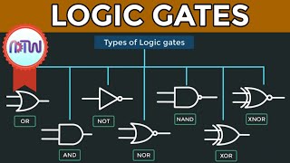
Logic Gates - An Introduction To Digital Electronics - PyroEDU

HTML-код
- Опубликовано: 7 сен 2024
- More Information: www.pyroelectro...
To join this course, please visit any of the following free open-access education sites:
Ureddit: / an-introduction-to-dig...
P2PU: p2pu.org/en/co...  Наука
Наука


Finally, a presentation format I understand. Thank you.
Put the fear of God into heart
Great
hi everyone ,if anyone else wants to discover introduction to electronics courses try Letza Easy Electronics Lessons (do a google search ) ? Ive heard some unbelievable things about it and my m8 got great results with it.
Incredible! One of the best overall explanations to logic and chips. I can't believe you packed it into 13 minutes.
I got struck onto this for many weeks and I had no idea what's going on . But , joining onto this channel really gave me a Clear understanding what's been really going on .
VERY well done and clearly explained for laymen, on a fairly complex subject. Thank you for your efforts.
This is what we need to really learn. Probably the Best Tutorial I've ever watched! WOW WOW WOW!
Thanks for this helpful video. I understand it better now than when my professor explained it.
Holy crap, you managed to explain this concept miles better than my professor! Thank you so much!!
I never saw this video before, but This was soo much better than any other video and self study I did before. I have done in Ece322 introduction to logic gate, but this one sure is the most comprehensive video I have Watched thank you!
Thaaaank you soo much you helped me doing my universty homework 😊😃
This helps a lot! Big thanks to you guys!
Passed my midterm thanks to this!
so fu***** helpful, I can't even! I love the experiment part shows exactly how I can use them in my project thanks!! thumbs way up!!
helped a lot(in correct time)
thanks...
When I was messing around on a logic simulator app on my phone I found something interesting. if you ignore something called gate propagation delay, and you connect the output of the not gate back to its input, you get an infinitely fast square wave, as if you feed the output of an inverter back to its input you get an infinite recursion.
Finally, a very easy to understand video for beginners
Thanks a lot! I've been waiting for a tutorial of this sort...
I love the epic intro and then something extremely nerdy xD love this explanation!
Comprehensive excellent explanation , Thank you Professor :)
thax..this video is very helpful n easily explain..to form all basic gates
Dude, subscribing for the intro alone. Shits dope.
Very detail the actual demo of how to make it is especially helpful,
Most excellent tutorial. Thank you.
I have spent months researching into circuits and found a fantastic website at Gregs Electro Blog (google it if you're interested)
Excellent visual presentation!
Wow, this was an excellent presentation. Thank you!
it helped a lot as missed my college practicals ...!!!😉
Wow, great animation and best knowledge
hi guys, the best results that i've had was by using the Gregs Electro Blog (i found it on google) definately the most useful info i've followed.
Most excellent tutorial. Thank you
If you're a noobie, it takes about 15 mins. to understand, which is great! :)
Thanks for this.
Great stuff. I'm doing course on this without a maths background, we had the intro to Boolean logic today and our first labs tomorrow morning! This has helped clarify the connection between logical and circuitry and helped prepare me :) thanks!
Very well explained, thank you!
Great demonstration, I indeed understood it, I appreciated it. Thanks 😎✌️
Well explained!
Its really a useful and very good video. Thanks
Is there microprocessor videos? Or micro controller is the same ? I going to major in EE and i have learned this and I'm moving on to microprocessor and more but I wants get a head start so i won't struggle in class. The video is great and it refresh my memories a lots. Thanks
I always say it and gotta say it again, that intro is damn mad
Brilliant tutorial, thanks !!!
What is the difference between pull-up and pull-down resistors again?
pull-up resistor creates high voltage if there's no other voltage source connected, pull-down resistor creates low voltage (ground) in the same case
Jesus bless you for helping out. Amazing explanation
Nice explanation!
Omg i actually understand it now...very good tutorial.
easy to understand, thank you!!!!
This helped a lot for trouble shooting
Hey everyone, the greatest results that ive had was by following the Gregs Electro Blog (just google it) definately the most helpful course i've tried.
Thanks from Swedan.
Very nice video for study....
Very Helpful Video Sir,
Thank You!
Best tutorial thanks i understood everything
simple and effective...thanks
Very good tutorial learnt alot
THANK YOU ;')
Really helpful
So how can you tell the difference between an AND, OR, or NOT chip just by looking at it?
Are you supposed to remember it by its number?
Yikes!
A *simple solution* would be that the manufacturers write "AND", "OR", or "NOT" on the circuit to make it clear what it does without the need to memorize a table or series of circuit numbers. :)
An *improvized solution* would be me sticking tape on the circuit and labelling it myself. :D
Don't mind me. This is a personal pet-peeve of mine lol.
That would be a solution if only a few types of those IC exist, but the coding is needed as we have a LOT of different chips
I can imagine. Too bad they didn't implement the word "AND", "OR", or "NOT" into the ID.
Instead of calling it a "7402", they could call it an "AND-7402".
That way you know what it is at a glance, and then the number tells you what type of AND chip it is, so the number could actually be shortened. :D
thanks a lot for uploading this amazing video....
Why is the regulator necessary? Why not use a resistor to drop the 9v to 5v?
Well, only a single resistor can not create a voltage drop. So for that purpose we'll need a resistive voltage divider. But there is some problem. As other components in the circuit have their own resistance they also work as loads which ultimately creates a different voltage than we need. A 5V zener diode could be used but it may not handle huge loads or cannot supply sufficient current as a series resistor must be used before the zener, which will limit the current. Whereas using a simple linear voltage regulator makes everything simple, it can even handle upto approx 1.5 Amps of current.
Thank u sooooooooooooooo much for this explanation
thank you very much i understood many things
This is really fantastic!
In general, is it a good idea to use HC family for similar circuits with LEDs? The specs are saying "±4 mA Output Drive at 5V".
I have a 7905 regulator instead of 7805 i.e. a -5v regulator. Can I just replace grnd by this regulator and give the grnd connection to the +5v pin of IC? In that way the +5v pin will still have a higher voltage.
very well explained
how to provide electricity for each ELD independently in this circuit?
very excellent video.thank u sir...
Thank you
Wow now I understand, thank you
Really superb man
Why you don';t need a pull down resistor for the inputs? If I don't use a
pulldown resistor for the inputs, the output has unexpected results.
Thank you.
What is "not" 1+1= 1 implying , over current ot voltage is reducing current power / watt and increasing heat? Stall not gates from compu of mine
8:43 - WRONG: the two left LEDs are connected directly with the power source, there is no interference of the IC.
Thanks for your video, i really like it. i tried to set up the not gate, when the input is zero, the light is on, but when the input is one, the light is still on but a lot dimmer, not off. Is there anything wrong with the gate ? i only used 5 V, pls help. Million thanks!
Neat presentation
awesome video
Really useful thanks man
i set the circuit up identically, but i always seem to get zero as an output, regardless if the input is high or low
Еasily and clearly.
Amazing video
Can I buy this kit with all the components your using in this video together or do they have to purchased separately. I’m very green to this and want to get a head start before we are doing this in school? Thanks for the video 😎
Would you show the calculations for current and voltage?
how do you switch on/off the led's ? how come all three leds are connected to ground for the and gate ?
very good explan...
QUESTION! Why do we need the resistors as part of the circuit? I don't think you talked much on those?
To stable the electricity or the current in the circuit
how is the input and output changed?
Make some also basic practical video like this with breadboard 😊
Could you show how to build these gates using transistors instead of IC´s?
So 1+1=1 means two ways electric current charged of same watt ?
Thanks for creating this video, it is very helpful!
How are you getting the lights to turn on to see if the logic gate is correct?
Can you make a video on schmitt triggers & flip flops please
wow amazing trick logic gates
If the 7805 regulator is only for 5v, why does it have a heatsink mounting hole?
Because of the 7805's low efficiency, if you are regulating 9v to 5v at 100 mA, the power lost is 400 mW, which is a LOT
thank you very much......
Comprehensive tutorial
nice video ...thanks,,
Thank you. Subscribed.
I dont know why my output LED doesnt glow.Really have no idea
It really helped me
Thanks
Great video :-)
well taken the point
Thank u very much sir
Thank you.