LCS - 09a - Mechanical systems with rotational and translational displacement

HTML-код
- Опубликовано: 5 фев 2025
- This lectures explains the mathematical modeling of mechanical systems when there are both the rotational (angular) and translational displacement. An example is presented to explain the modeling procedure.


Mashaallah exactly what i was looking for! Great work !
Alhamdulillah, exactly what I was looking for. May Allah bless you brother
Awesome Explanation Sir !!!
.
@MAFarooqi
Thanks sir , you are very good
But I have a question
I think this is an error in the equation of theta 2 .
10:40
The sign of [ r*F(s) ] should be positive not negative.
Does my thought true or I don't understand well ?
With the assumed directions of displacements, the arrangement with linear displacement applies an upward force on the rack and pinion arrangements. This opposes the angular displacement, as indicated in the free body diagram. Therefore, there must be a negative sign with r*F.
The FBD in the video is as same as my answer. from the FBD we see that the term (F(s)*r) (CCW) opposes the angular displacement (CW) and also the term (J2)(CCW) opposes the angular displacement (CW) so the term (F(s)) and (J2) both have the same direction (CCW), but in the equation (J2) positive and (F(s)) Negative
@@AhmedHamada-lg8hl let me check it.
Yes, you are right. The free body diagram is correct and there should be positive sign with r*F.
Thanks ,sir for your replying .
you are one of the most and the best people in explaining engineering problems .
your RUclips channel is very helpful.
very thanks to you ,sir ♥️♥️♥️
superb explanation sir, thank you!
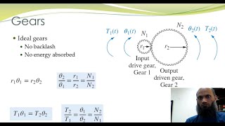
What if the gear ration is not 1:1. how does it effect our model ?
Rack and pinion arrangement concerts angular displacement into linear displacement and vice versa. In rack and pinion arrangement, we do not talk about gear ratio, rather the linear and angular displacements are related by the radius of the puppy, which is considered in this example.
If you are interested in modeling of systems with gears, you may take other lectures in the playlist.
Sorry to bother you, but I have a question, shouldn't the displacement x1 be defined upwards? because the way I visualize it, if the gear rotates in the direction that is given by the initial torque, it pulls up the mass instead of moving it downwards.
1. If you look the whole arrangement from the right side, the applied torque tend to rotate the gear in clockwise direction, that is, the mass will move downwards.
2. There is another important point which needs further elaboration. That is, you can even assume the direction x1 upwards, the model will be still correct, however, now x1 will have negative magnitude.
What does this system represent
What systems use such me mechanism
In robotic systems, there are many parts which involve rotary as well as linear displacements.
Salam sir...sir plz tell us about the book that which book u used...plz it will be more easy for us to watch ur lecture and then read books for more details plus excersise. Sir must rply plz
Control Systems Engineering by Norman Nise.
Your explanation is so good but this problem is so hard and lengthy
Yes, this is a bit hard problem. However, if you completely understand the modeling of mechanical systems with translational displacement and modeling of mechanical systems with rotational displacement, the problem underhand becomes easier.
Shouldn't it be (- (M * r^2 * s^2) - (fv * r^2 * s) - (K2 * r^2) + .......) * theta2 in substituted form of the theta2 equation ?
Do you mean that there should be negative sign with the second term in the second equation?
Yes. I have same question. At 13:26, from 2nd blue eq to 3rd eq, I found -rF(s) suddenly became rF(s).
+) I found rF drawn the same direction with the elements of theta2 in the FBD. I think you just might have miss-typed the sign of rF.
arigato
👍🏼