I understand fully how PID works but lack the understanding of Arduino to implement. Would you be willing to share the code or perhaps a similar bit of code to get us going in the right direction
Great Tutorial. It's quiet clear explanation for me. I am waiting for the next video explaining Self Balance 2 wheel robot as you promise in the end of this video. I plan to build it. Pls release it ASAP. Thank you so much
+Mugi Raharjo Thank you for your comment!. The balancing robot was a quite big project and I will divide it in several videos. I hope, I can start the series around Christmas this year. First, I have to finish my ESP8266 tutorial series...
Wow! Thank you so much for a fascinating and instructive video. I came across you channel purely by chance, but what a wonderful find. I have, of course subscribed, and I hope many more people do too.
+yousef Alotaibi Unfortunately, the code is still in a very experimental stage and I have to work on it. In the next weeks I hope, I can reactivate my wind tunnel project again and then, I will post the code.
Hello. Will you be able to share the code of this fan pid controller. I have made a home made jet engine and this code would be perfect to use as throttle controll. I have a hall sensor with a amplifier and a schmitt trigger so that would be the same as you. Insteed of driving a fan it would be driving the fuelpump. I need this function because today when i am igniting the afterburner the rpm off the engine goes down alitle bit. I have a ordinary 10k potentiometer as throttle.
I think it was on the boundary of the Arduino to get it higher than Andreas got it. Servo positioning ok. Precise motor control needs a lot more power. My favorite workhorse is a uC from ST Micro. It can do 10 times as much in one tenth the time. Nice tutorial.
Did you end up only using the I controller since it got you exactly the 2000 RPM, or did you still end up using the proportional part of the controller? Great video!!!
Great tutorial, I am working on similar speed control problem, what kind of sensor is used for speed sensing(how many pulses per revolution?), what is the sampling interval, can we use time interval as the control variable?
This may be more work than it's worth, but would you ever write some kind of numerical method algorithm to find the right parameters? I mean, you'd start it up, and it would evaluate its own performance. You could put your hand over it and do other things to perturb it, and over time, it'd learn?
That is a whole other story and so far, I have no knowledge in the area of "self learning". A big part of the Silicon Valley for the moment is in this topic, and maybe, one day, we get ready made algorithms to be used by people like me. One big problem in real world examples exists however, and the self balancing robot is a good example: It falls down if the error is too big. So, you would need a lot of patience to restart it after every "learning step" (or you include a "self stand-up" functionality)
what if the motor speed is lower than the required value, wouldn't the P part = current value - required value. Or do I just take the absolute value of the difference
Great Tutorial! helped me with my bachelor thesis!! :D But could you please tell me how you plotted the graphs? I think it would be great if I had some of those in my report!! :D
Glad to her that. So, I hope, it will be accepted. (I already corrected a few of them during my time as a teacher...). I do not remember exactly, but I think, I used the procedure described in video #9.
awsome stuff, great channel... can it be used to control servos in a cnc-like maschine with incremental optical encoders? i heard there are better methods for this, but the pid seems quite simple
+grmlje grmone Thank you for your compliment. Usually you do not need an additional PID controller for a servo because the servo itself consist of a motor, an position encoder (often a potentiometer) and something like a simple "PID" controller. But usually, they are very inaccurate compared what you need for a CNC. And usually, they have just 180 or 360 degrees range. If you exchange the word "servo" with "motor", then you are right. There are some videos where people used a motor, a rotary encoder (usually optical), and a controller. This seems to work and is a perfect application for a PID controller. Most of the smaller CNC routers (including mine) however, use stepper motors.
+Andreas Spiess yeah, i should have said dc motors.. i added some transmission to them and they are going to become servos after i decide what control to use (pid and pll are the main candidates for now). i would love to see a video on pll in your style all the best in the new year :)
+Andreas Spiess yeah, phase locked loop.. im intrested in it because im working on a diy cnc router atm. but im working on a piece of code as well that will allow me later in life to easily connect almost any kind of motor and easily control it, could be useful for future hacks, and i want to cram every type of control into it for more flexibility. i dont know much about pll.. yet
hallo! I am on a very base-level and right now in a project where we use the hub-ee wheel (a wheel with built in encoder), if I understand you right and want to use a PID-controller to get the wheel to a specific position, could I write something like this to get a P-controller: int motor1speed; int actualPoint; int setPoint; int diff; int p; p=0,8; setPoint=340; void setup() { motor1Wheel.setupPins(8,11,9); } void loop() { diff=actualPoint-setPoint; motor1speed=diff*p; if (motor1speed>255){ motor1speed==255 } if (motor1speed
1. Basics are ok. But I think, you need also negative speeds because your motor could go across the position and has to reverse. 2. Pay attention to the sign of the difference. The speed has to be different accordingly (positive or negative) 3. The I and the D parts have to be included as the p part. (diff *p + integral(diff) * i + diff' x d). You can take my code as an example. 4. I would start with the p only part. only if it works, I would add the I part. I do not think, you will need a d part.
Every time I saw that poor motor being abused by the varying signals I couldn't help but laugh and think "Fan for sale. One previous careful owner." ;)
I meant the motor of the fan, not the vehicle. Sorry, I should've been clearer. I'm really enjoying your videos by the way. I like you you showed the troubleshooting process in this video. Thank you. "Hop schweez" ;)
@@AndreasSpiessThanks andreas Can you please guide (1)pid max pid min depends on output range or error percentage or fixed range (2) In pid integral value and derivative values should be updated at what speed. I mean integral and derivative are based on time ? some standard pids like siemens give i and d in seconds. can you explain and guide. Thanks P.R.B
Read about, very interesting and important subject to learn. Maybe thats inspire you to make new video about it. Without integral windup maintance there could be a lot of problems in control systems.


You explained the details amazingly , definitely enforced my understanding of your project and PID as a whole. Cheers.
Thanks!
Incredible clear explanation of PID closed loop controller. I use them for my quadcopters. Congratulations!
+Pablo López Thank you for your very nice comment!
Great job on the "PID controller" part- very clear and easy to understand. Not so great on the "using an Arduino" part.
:-)
Thanks for taking the time to do this, excellent!
You are welcome!
I understand fully how PID works but lack the understanding of Arduino to implement. Would you be willing to share the code or perhaps a similar bit of code to get us going in the right direction
Great Tutorial. It's quiet clear explanation for me. I am waiting for the next video explaining Self Balance 2 wheel robot as you promise in the end of this video. I plan to build it. Pls release it ASAP. Thank you so much
+Mugi Raharjo Thank you for your comment!. The balancing robot was a quite big project and I will divide it in several videos. I hope, I can start the series around Christmas this year. First, I have to finish my ESP8266 tutorial series...
Your nice instructive video cured my hang-over. Thanks!
+PaulExo :-)
Wow! Thank you so much for a fascinating and instructive video. I came across you channel purely by chance, but what a wonderful find. I have, of course subscribed, and I hope many more people do too.
+Gareth Jefferson Thank you very much for your support. Comments like yours help me if I am sometimes a little behind schedule with my videos!
+Andreas Spiess could you please show us the code
+yousef Alotaibi Unfortunately, the code is still in a very experimental stage and I have to work on it. In the next weeks I hope, I can reactivate my wind tunnel project again and then, I will post the code.
Eureka! Endlich gschnallt. Danke für die super erklärig.👍👍👍
Gern geschehen!
Very excellent video and tutorial. Again, I learned something interesting.
Thanks for the nice words!
Hello. Will you be able to share the code of this fan pid controller. I have made a home made jet engine and this code would be perfect to use as throttle controll. I have a hall sensor with a amplifier and a schmitt trigger so that would be the same as you. Insteed of driving a fan it would be driving the fuelpump. I need this function because today when i am igniting the afterburner the rpm off the engine goes down alitle bit. I have a ordinary 10k potentiometer as throttle.
Amazing explanation
Thank you!
Your video was great!! Thanks..
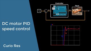
How have you plotted the graph of speed and other variables? Which software did you use?
Just with Excel. You might have a look on my video #6 where I show how you can connect Arduinos with Excel.
Ein Coop Kunde ;-). Wie immer herzlichen Dank und bis zum nächsten Video.
+norm1124 Nicht ich: Meine Frau. Ich tendiere eher zum Landrover ;-)
I think it was on the boundary of the Arduino to get it higher than Andreas got it. Servo positioning ok. Precise motor control needs a lot more power. My favorite workhorse is a uC from ST Micro. It can do 10 times as much in one tenth the time. Nice tutorial.
Or an ESP32 ;-)
Did you end up only using the I controller since it got you exactly the 2000 RPM, or did you still end up using the proportional part of the controller? Great video!!!
+Luis Camal At the beginning the D part is important. Later, the I part gets more important, when the difference is smaller
thanks a lot, I was struggling with this
Glad it helped!
Hello and direct one question: Did you use a PID-Library or did you implement that yourself?
I implemented it myself
Thank you very much! Top-notch tutorial!
+Owl Sight You are welcome!
Great tutorial, I am working on similar speed control problem, what kind of sensor is used for speed sensing(how many pulses per revolution?), what is the sampling interval, can we use time interval as the control variable?
It was all built into the fan and I do not remember the exact numbers. 4 wire fans have a sensor for RPM built-in
This may be more work than it's worth, but would you ever write some kind of numerical method algorithm to find the right parameters? I mean, you'd start it up, and it would evaluate its own performance. You could put your hand over it and do other things to perturb it, and over time, it'd learn?
That is a whole other story and so far, I have no knowledge in the area of "self learning". A big part of the Silicon Valley for the moment is in this topic, and maybe, one day, we get ready made algorithms to be used by people like me. One big problem in real world examples exists however, and the self balancing robot is a good example: It falls down if the error is too big. So, you would need a lot of patience to restart it after every "learning step" (or you include a "self stand-up" functionality)
You explaine amazingly thank you very much for this informations ^^, big thumbs up sir.
You are welcome!
Good video, example code would be a very helpful addition.
This is quite an old video and I do not have the sketches handy. However, there is an Arduino library for PID.
Thanks for the reply, I figured it out with an example that came with the PID Library.
what if the motor speed is lower than the required value, wouldn't the P part = current value - required value. Or do I just take the absolute value of the difference
I do no more remember the details. But the formulas should be correct.
Very good tutorial on PID thankyou
Thank you!
Great Tutorial! helped me with my bachelor thesis!! :D
But could you please tell me how you plotted the graphs? I think it would be great if I had some of those in my report!! :D
Glad to her that. So, I hope, it will be accepted. (I already corrected a few of them during my time as a teacher...).
I do not remember exactly, but I think, I used the procedure described in video #9.
Alright, I will take a look at it then.!!
Thanks a lot :)
awsome stuff, great channel... can it be used to control servos in a cnc-like maschine with incremental optical encoders? i heard there are better methods for this, but the pid seems quite simple
+grmlje grmone Thank you for your compliment. Usually you do not need an additional PID controller for a servo because the servo itself consist of a motor, an position encoder (often a potentiometer) and something like a simple "PID" controller.
But usually, they are very inaccurate compared what you need for a CNC. And usually, they have just 180 or 360 degrees range.
If you exchange the word "servo" with "motor", then you are right. There are some videos where people used a motor, a rotary encoder (usually optical), and a controller. This seems to work and is a perfect application for a PID controller.
Most of the smaller CNC routers (including mine) however, use stepper motors.
+Andreas Spiess yeah, i should have said dc motors.. i added some transmission to them and they are going to become servos after i decide what control to use (pid and pll are the main candidates for now). i would love to see a video on pll in your style
all the best in the new year :)
+grmlje grmone Happy New Year to you, too. With PLL you mean Phase Locked Loops? What kind of applications you have in mind?
+Andreas Spiess yeah, phase locked loop.. im intrested in it because im working on a diy cnc router atm. but im working on a piece of code as well that will allow me later in life to easily connect almost any kind of motor and easily control it, could be useful for future hacks, and i want to cram every type of control into it for more flexibility. i dont know much about pll.. yet
Thanks. Excellent video !!
:-)
yeh! this is what I'm looking for! thanks!
You are welcome!
Is the ratio of P and I the same usually (by some factor) for servos as well?
There is no particular ratio between p and i. Both have to be adjusted for every application
Great learning material
Thanks!
Very nice. Thank you for open my mind...
You are welcome!
thank you for your fantastic explanation, do you have any example code? Thank you so much!
You find an example in the self-balancing robot
hallo! I am on a very base-level and right now in a project where we use the hub-ee wheel (a wheel with built in encoder), if I understand you right and want to use a PID-controller to get the wheel to a specific position, could I write something like this to get a P-controller:
int motor1speed;
int actualPoint;
int setPoint;
int diff;
int p;
p=0,8;
setPoint=340;
void setup() {
motor1Wheel.setupPins(8,11,9);
}
void loop() {
diff=actualPoint-setPoint;
motor1speed=diff*p;
if (motor1speed>255){
motor1speed==255
}
if (motor1speed
1. Basics are ok. But I think, you need also negative speeds because your motor could go across the position and has to reverse.
2. Pay attention to the sign of the difference. The speed has to be different accordingly (positive or negative)
3. The I and the D parts have to be included as the p part. (diff *p + integral(diff) * i + diff' x d). You can take my code as an example.
4. I would start with the p only part. only if it works, I would add the I part. I do not think, you will need a d part.
what software do you use to collecting data?
I use a Excel datalogger described in one of my videos
can you plz help me to make a code for dmx stapper motor with encoder
I am a RUclipsr and share my knowledge in my videos.
Can you provide the arduino code ?
No, I do not have it anymore. Sorry.
Every time I saw that poor motor being abused by the varying signals I couldn't help but laugh and think "Fan for sale. One previous careful owner." ;)
+Bernhard Hofmann That's a Landrover. It is not abused. It is just used inside its specifications 😉
I meant the motor of the fan, not the vehicle. Sorry, I should've been clearer. I'm really enjoying your videos by the way. I like you you showed the troubleshooting process in this video. Thank you. "Hop schweez" ;)
how to choose pidmin and pid max values
By experimenting
@@AndreasSpiessThanks andreas
Can you please guide
(1)pid max pid min depends on output range or error percentage or fixed range
(2) In pid integral value and derivative values should be updated at what speed. I mean integral and derivative are based on time ? some standard pids like siemens give i and d in seconds. can you explain and guide.
Thanks
P.R.B
Excellent....... :-)
Thanks!
Great!
Thanks!
What about integral windup?
I do not know.
Andreas Spiess thats very important part of pid controllers.
So I still do not know. Never heard of.
Read about, very interesting and important subject to learn. Maybe thats inspire you to make new video about it.
Without integral windup maintance there could be a lot of problems in control systems.
lovely explanation ...... 😘
I hope you re-write code too since you lost it.......
This is an old video. The chance is small that I will publish the code
excellente Arbeit. besser hätte man die regler nicht zusammenfassen können ein viedo für ein kamera stabilisation wäre toll :)
+1q1q1q1q1q1q1qw Vielen Dank für das Kompliment. Ich werde das Thema "Kamerastabilisator" auf meine Liste nehmen.
ja vielleicht wie man die pid lib richtig verwendet um einen schnellen gimbal zu bauen danke :D
Sir, can i have your email sir?
No