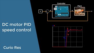
I designed this system with an approach based around how I would like to have been thought it originally years ago when I studied it. All credit to the education I got, it was excellent, but for all the theory I had a firm grasp of, I failed utterly at being able to apply it in real life outside of simulations in Matlab. I think if I had been able to sit down with a physical system in front of me, code the microcontroller and see the outputs in real time it would have done so much for my understanding. My hope is that this is an accessible resource for people who are coming at this as a beginner hobbyist or a student, like I was, with a good understanding of the theory but fuzzy on the real world application.
one of the most through explanations ive seen, so refreshing to see behind the scenes instead of someone just using a library that makes everything into a black box
Man, at my 3rd year of engineering and i am thinking of making a stability project with 2 brushless motor, but I wasn’t sure if how easy it is, but after watching your video now I’m 💯 sure i will be doing it. The hand gestures, the way you explain and the plan you choose to explain the code and the oscillation graph it was all perfect. Thank you ❤
I've been tuning PID's for 25 years from chain driven sloppy movements to oven temps to CNC, and thought I was accomplished when I used the PID library.. I wish I had seen this years ago. Very well done and simplified the black box magic. Those block diagrams are great but thinking thru the math is essential for tuning intuition.
Thank you! This was exactly what I needed to implement a motor speed controller. Your explanation was concise and clear and your video was enjoyable to watch.
Many thanks brother, I´ve been interested in making balancing robots for fun, and donate the project to my university so other students can see the helpfulness and importance of PID in control systems. With this explanation I feel more confident in starting this iniciative.
That’s a great idea! Happy this helped you! I have a project that I intended for a similar usage, feel free to check it out here: careyi3.github.io/balance_beam_kit/
I controlled the temperature in a greenhouse (90m*20m*6m) almost entirely on the derivative portion - the time constant of that volume of air required it.
Thanks for this video and especially the link to the code. This helped me to understand the PID calculation. In code format its much easier to understand than to read Wiki and see the long formula with strange symbols :D
Thank you for this video! I'm currently working on a personal project - creating something like a diesel engine controller based on the VP37 pump. There's a type of inductive solenoid that adjusts the fuel dosage based on a PWM signal it receives. The feedback signal is from a Hartley generator, generating a DC voltage that changes depending on the position of the actuator. It seems like a straightforward task - just drive the solenoid with the right waveform based on the feedback voltage... But unfortunately, it's not that simple! Unexpected problems arise, such as the coil heating up during operation, requiring compensation for temperature drift, or fluctuations in the solenoid's supply voltage... The solenoid itself is mounted on springs and can oscillate on its own... :) I struggled with this a bit, and I have to say that PID behaves impressively well in this regard, better than all my other solutions. I'm still dealing with the issue of voltage fluctuations - when the coil's supply voltage changes, the solenoid changes its position. After a while, the PID stabilizes it, but there's still some fluctuation in the actuator's position. Thanks again for the great explanation in your video!"
Wow, that sounds like a complex problem, but it sounds like you understand it very well, only a matter of time before you fully crack it for sure! You are welcome, I’m glad this helped you! Keep up the great work
This is an amazing content . i wish there was a quick way to calculate the pid values and tune them quickly since as an engineer you have dead lines to meet
Great point, real engineers can build actual models of these things and simulate different PID values, it’s never going to be 100%, there is a trade off of detailed models and the time it takes to build etc. There are also methods for tuning PID controllers. However, it might end up being faster to do it manually. You also have to think about if you are building a product, the base tuning might come from a model and simulation, you only need to build that once, then you can tweak and tune it afterwards.
very strong video! could you do a follow up video implementing a MPC control algorithm for the same system in Arduino? It would hightlight the key differences and relative performance really well I think
Well explained, but, this is a digital system which is a fast response system which means that the closed loop responds quickly, when you start implementing this with a slow response like a heating element this response is very slow because the closed loop has to wait for the "response" from the thermistor that monitors the surrounding heating. This gets very interesting very quickly...... Nice video and a good delivery.
Thanks! Yeah, you are 100% correct, this is also a totally contrived example, but it gives a clear picture of what is going on and can be done with minimal parts etc. You have me thinking of a little desktop temprature based control demo now... Maybe something for a future video!
@@careyian 🤣😂 Yes... I am busy with a pulltruder that has to use PID to control the heated extruder with.... So this video had me for a full 29minutes and 50seconds...... PID is a dark art and can send one down a horrible rabbit hole!🤣😂
That's a great explanation; however, I think we should consider making the PID gains more adaptive to enhance the code's generality and accuracy. Would this improvement be beneficial or will it add unnecessary overhead to the code?
@@careyian I mean if we can make a simple method that changes the gains within the runtime based on the time the system takes to reach its steady state. Therefore we will have a better gains for the next time.
Than you very much! Your video has given me a good understanding of how PID works. I do have a doubt though, the integral term accumulates over time so if it keep on adding up it would contribute more to the error calculation right? I have seen some vids where they have a saturation limit, but even then there is no way to reduce this unless it overshoots right? Should we reset the addition over time from time to time if it reaches the set-point?
That is a really excellent question. In theory if the error oscillates around the set point, the integral term should settle assuming the error goes to zero and so should end up stable. However, there are cases where this might not happen and you end up with something called integrator windup happening. You can could avoid this by placing limits on the max values or periodically clearing the integrator value back to zero when you approach stability.
one thing that confuses me is when the actual goes above the set point, won't the proportional and derivative terms become negative , so couldnt there be a case where the output is negative and you try and write a negative voltage to the pin?
Good spot, yes that can in theory happen here. In practice those negative values will be fighting against the accumulated positive integral error, so they aren’t likely to make the overall output negative. Specifically here a negative value being fed into analogWrite will not behave correctly as it will write the 8bit unsigned value of it directly to the register, which you wouldn’t want. What this implementation is really missing is scaling on the output to ensure that whatever the value that gets spit out, it’s always within a certain range.
Hi, I don't know what you mean, could you elaborate? The values will probably be different if you set this up yourself and you will have to tune them yourself.
Great video 👍🏽 I have one big question that I am not able to solve… In my scenario, I need a PID control that prevents my motor from accelerating beyond 6 km/h, even with the throttle fully engaged. That means my target is 6, and my actual value is the measured speed at the front wheel. However, the PID has to output a value between 0-255 for throttle regulation. How do I establish the correlation here? Your code example doesn't provide me with values within this range because I'm only feeding it with speeds.
The trick here is you need to remember that the scale of your units doesn’t matter. If your input into the PID is some value of speed, as you mentioned k/h, you need to scale your PID gains to give you output values in the range you are interested in. You can also write some scaling logic if you want to bring them into the same kind of range, but that’s up to you.
What if I don't use the dt value? I mean for integral instead of integral +=error*dt I will use integral+=error. The same for derivative. The dt determined by the timer interrupt. Meaning it is a constant value. But I don't use it in calculations. Will it work correctly?
Great question, so the dt or sampling time really depends on what you are trying to control and what frequency your system will run at. For example if you have a slow system, it might be kind of pointless to sample it very quickly. Where as a fast system needs to be sampled more quickly. Without knowing what you are sampling, I’d say a basic model without the dt value might work. Assuming it’s a simple system and the period is always the exact same. Assuming you know dt based on the timer, I’d suggest just including it to reflect what is actually going on instead of abstracting it away.
Well that’s a good point about being at optimal performance. If you use dt you can tune the system by altering the value and seeing how it responds. You are effectively assuming that that the sampling time is 1 second by leaving off dt. If you include it to match your system you can see what effects on the response the sampling rate will have on the PIDs outputs. In the real world, your sampling time is probably much faster, so you should include this so that the frequency that your system is operating at and the frequency that your PID appears to be operating at are the same.
So the units aren’t super important, they will effectively scale the values differently. However, seconds are the standard unit of measurement for time, so by converting to this you are ensuring the time measured reflects what’s actually happening. It won’t really break anything as such if you use different units


I designed this system with an approach based around how I would like to have been thought it originally years ago when I studied it. All credit to the education I got, it was excellent, but for all the theory I had a firm grasp of, I failed utterly at being able to apply it in real life outside of simulations in Matlab. I think if I had been able to sit down with a physical system in front of me, code the microcontroller and see the outputs in real time it would have done so much for my understanding. My hope is that this is an accessible resource for people who are coming at this as a beginner hobbyist or a student, like I was, with a good understanding of the theory but fuzzy on the real world application.
one of the most through explanations ive seen, so refreshing to see behind the scenes instead of someone just using a library that makes everything into a black box
Thanks for your kind words! Glad you liked it!
your code clean, your explaination clear, your voice good --> 10/10 video, thanks bro !
Thanks friend! Glad you liked it!!
Man, at my 3rd year of engineering and i am thinking of making a stability project with 2 brushless motor, but I wasn’t sure if how easy it is, but after watching your video now I’m 💯 sure i will be doing it.
The hand gestures, the way you explain and the plan you choose to explain the code and the oscillation graph it was all perfect. Thank you ❤
That’s so great to hear! Wishing you all the best with your project!
I've been tuning PID's for 25 years from chain driven sloppy movements to oven temps to CNC, and thought I was accomplished when I used the PID library.. I wish I had seen this years ago. Very well done and simplified the black box magic. Those block diagrams are great but thinking thru the math is essential for tuning intuition.
Hey, thanks for your comment! Glad you liked it
Thank you! This was exactly what I needed to implement a motor speed controller. Your explanation was concise and clear and your video was enjoyable to watch.
Hey, thanks! That’s great to hear, really glad it was useful for you!
Many thanks brother, I´ve been interested in making balancing robots for fun, and donate the project to my university so other students can see the helpfulness and importance of PID in control systems. With this explanation I feel more confident in starting this iniciative.
That’s a great idea! Happy this helped you! I have a project that I intended for a similar usage, feel free to check it out here: careyi3.github.io/balance_beam_kit/
Man, this is perfect. ❤
Respect from EGYPT.
Very welcome!!
Loved your explanation throughout, very easy to follow and understand. Also, it's visible that you love this stuff too. Makes it an interesting watch.
Hi Tim, glad you liked it, thanks for your feedback!
doing 3rd year mechanical, and wanted to see actual application of such, this video is great.
Great to hear!
I controlled the temperature in a greenhouse (90m*20m*6m) almost entirely on the derivative portion - the time constant of that volume of air required it.
Cool!
Thanks for this video and especially the link to the code. This helped me to understand the PID calculation. In code format its much easier to understand than to read Wiki and see the long formula with strange symbols :D
You are very welcome! Glad it helped!
Thank you for this video! I'm currently working on a personal project - creating something like a diesel engine controller based on the VP37 pump. There's a type of inductive solenoid that adjusts the fuel dosage based on a PWM signal it receives. The feedback signal is from a Hartley generator, generating a DC voltage that changes depending on the position of the actuator. It seems like a straightforward task - just drive the solenoid with the right waveform based on the feedback voltage... But unfortunately, it's not that simple! Unexpected problems arise, such as the coil heating up during operation, requiring compensation for temperature drift, or fluctuations in the solenoid's supply voltage... The solenoid itself is mounted on springs and can oscillate on its own... :) I struggled with this a bit, and I have to say that PID behaves impressively well in this regard, better than all my other solutions. I'm still dealing with the issue of voltage fluctuations - when the coil's supply voltage changes, the solenoid changes its position. After a while, the PID stabilizes it, but there's still some fluctuation in the actuator's position. Thanks again for the great explanation in your video!"
Wow, that sounds like a complex problem, but it sounds like you understand it very well, only a matter of time before you fully crack it for sure! You are welcome, I’m glad this helped you! Keep up the great work
@@careyian I'll likely get to it, but if you've got any ideas to speed up my thinking process, feel free to drop them! :D
very fascinating experiment and easy to understand, for something that I really struggle to learn.
Great, glad it was helpful!
Thanks for uploading this. Gigachad move
No problem!!
This is an amazing content . i wish there was a quick way to calculate the pid values and tune them quickly since as an engineer you have dead lines to meet
Great point, real engineers can build actual models of these things and simulate different PID values, it’s never going to be 100%, there is a trade off of detailed models and the time it takes to build etc. There are also methods for tuning PID controllers. However, it might end up being faster to do it manually. You also have to think about if you are building a product, the base tuning might come from a model and simulation, you only need to build that once, then you can tweak and tune it afterwards.
very strong video! could you do a follow up video implementing a MPC control algorithm for the same system in Arduino? It would hightlight the key differences and relative performance really well I think
Hi there, thanks for the comment, might do that in the future!
Thank you so much for your effort 👍🏻
Greetings from Germany
Welcome!
thanks mate, you helped a bachelor student here :)
Love to hear it! You are very welcome friend
Thank You so much!! Just what I needed.
You're welcome!
Well explained, but, this is a digital system which is a fast response system which means that the closed loop responds quickly, when you start implementing this with a slow response like a heating element this response is very slow because the closed loop has to wait for the "response" from the thermistor that monitors the surrounding heating. This gets very interesting very quickly...... Nice video and a good delivery.
Thanks! Yeah, you are 100% correct, this is also a totally contrived example, but it gives a clear picture of what is going on and can be done with minimal parts etc. You have me thinking of a little desktop temprature based control demo now... Maybe something for a future video!
@@careyian 🤣😂 Yes... I am busy with a pulltruder that has to use PID to control the heated extruder with.... So this video had me for a full 29minutes and 50seconds...... PID is a dark art and can send one down a horrible rabbit hole!🤣😂
Love it! Exciting project, hope it goes well for you!
this video is just incredibly good
Thanks so much!
awesome! thank you very much. You dont know how much I needed this
Glad I could help!
Respect from Viet Nam
Thanks!!
It is awesome! Very useful video for me
Glad it was helpful!
@@careyian sure
That's a great explanation; however, I think we should consider making the PID gains more adaptive to enhance the code's generality and accuracy. Would this improvement be beneficial or will it add unnecessary overhead to the code?
Hey there, what do you mean by adaptive?
@@careyian I mean if we can make a simple method that changes the gains within the runtime based on the time the system takes to reach its steady state. Therefore we will have a better gains for the next time.
Yeah, I guess you could do something like that if you wanted to. This is just example code, I have no plans to do anything more with it.
Thankyou very much for this one
You are very welcome! Glad you enjoyed it, hope it was helpful my friend
Than you very much! Your video has given me a good understanding of how PID works. I do have a doubt though, the integral term accumulates over time so if it keep on adding up it would contribute more to the error calculation right? I have seen some vids where they have a saturation limit, but even then there is no way to reduce this unless it overshoots right? Should we reset the addition over time from time to time if it reaches the set-point?
That is a really excellent question. In theory if the error oscillates around the set point, the integral term should settle assuming the error goes to zero and so should end up stable. However, there are cases where this might not happen and you end up with something called integrator windup happening. You can could avoid this by placing limits on the max values or periodically clearing the integrator value back to zero when you approach stability.
@@careyian thank you very much for the response! I'll google about Integrator windup and include limits on max and min values in my implementation
one thing that confuses me is when the actual goes above the set point, won't the proportional and derivative terms become negative , so couldnt there be a case where the output is negative and you try and write a negative voltage to the pin?
Good spot, yes that can in theory happen here. In practice those negative values will be fighting against the accumulated positive integral error, so they aren’t likely to make the overall output negative. Specifically here a negative value being fed into analogWrite will not behave correctly as it will write the 8bit unsigned value of it directly to the register, which you wouldn’t want. What this implementation is really missing is scaling on the output to ensure that whatever the value that gets spit out, it’s always within a certain range.
Appreciate for sharing !~ Would be grateful if could also share the hardware screenshot as well 😀
Hi Bruce, glad you liked it! If you follow the link in the description I have a circuit diagram there which should explain the hardware setup.
Do you have any video or technique for autotuning the kp, ki and kd values?
Unfortunately no, I usually always manually tune controllers
To achieve critical damping what is the value?
Hi, I don't know what you mean, could you elaborate? The values will probably be different if you set this up yourself and you will have to tune them yourself.
Great video 👍🏽
I have one big question that I am not able to solve…
In my scenario, I need a PID control that prevents my motor from accelerating beyond 6 km/h, even with the throttle fully engaged. That means my target is 6, and my actual value is the measured speed at the front wheel. However, the PID has to output a value between 0-255 for throttle regulation. How do I establish the correlation here? Your code example doesn't provide me with values within this range because I'm only feeding it with speeds.
The trick here is you need to remember that the scale of your units doesn’t matter. If your input into the PID is some value of speed, as you mentioned k/h, you need to scale your PID gains to give you output values in the range you are interested in. You can also write some scaling logic if you want to bring them into the same kind of range, but that’s up to you.
What if I don't use the dt value? I mean for integral instead of integral +=error*dt I will use integral+=error. The same for derivative. The dt determined by the timer interrupt. Meaning it is a constant value. But I don't use it in calculations. Will it work correctly?
Great question, so the dt or sampling time really depends on what you are trying to control and what frequency your system will run at. For example if you have a slow system, it might be kind of pointless to sample it very quickly. Where as a fast system needs to be sampled more quickly. Without knowing what you are sampling, I’d say a basic model without the dt value might work. Assuming it’s a simple system and the period is always the exact same.
Assuming you know dt based on the timer, I’d suggest just including it to reflect what is actually going on instead of abstracting it away.
Well that’s a good point about being at optimal performance. If you use dt you can tune the system by altering the value and seeing how it responds. You are effectively assuming that that the sampling time is 1 second by leaving off dt. If you include it to match your system you can see what effects on the response the sampling rate will have on the PIDs outputs. In the real world, your sampling time is probably much faster, so you should include this so that the frequency that your system is operating at and the frequency that your PID appears to be operating at are the same.
I am back with another question. I saw you convert the dt unit to second. Why? What should be the unit? Can I use ms, us or ns?
So the units aren’t super important, they will effectively scale the values differently. However, seconds are the standard unit of measurement for time, so by converting to this you are ensuring the time measured reflects what’s actually happening. It won’t really break anything as such if you use different units
@@careyian But the values will change 1000 times for ms. How this will not effect the result? I don't get it.
thx your ass pro❤❤❤❤
Sassy 💁🏻♀️