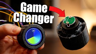
Using Rotary Encoders with Arduino

HTML-код
- Опубликовано: 6 фев 2025
- Rotary encoders are versatile devices that can be used both as controls and as instruments to measure the rotation of a DC motor. Today I will show you how to do both of those things using rotary encoders and an Arduino.
Complete article with code - dronebotworksh...
More articles and tutorials: dronebotworksh...
Join the conversation on the forum: forum.dronebot...
Subscribe to the newsletter and stay in touch:dronebotworksh...
We will look at two types of rotary encoders today. The first one is a very common control that looks a bit like a potentiometer but, as you will see, is much more accurate and versatile.
The second rotary encoder we’ll examine is attached to the back of the DC Gearmotor I’m using to build my DB1 robot.
Both encoders work on similar principles.
I’ll show you how rotary encoders can determine both the position and direction of rotation by using and comparing two output pulses. Then we will create and run a few Arduino sketches to put them to use.
In the first sketch, we will see how to read the value from a rotary encoder control. Next, we will add a servo motor and precisely control its position with a rotary encoder.
After that, we will bring out the servo motor encoder. We will look at the output pulses on an oscilloscope, then we will connect it to an Arduino to build a tachometer of sorts, reading the RPM of the motor.
Here is the Table of Contents for today's video.
00:00 - Introduction
02:15 - Rotary Encoder Operation
06:13 - Basic Rotary Encoder Control Sketch
12:09 - Controlling a Servo Motor
18:40 - Rotary Encoder on a DC Gear Motor
21:08 - Reading RPM from a Motor
As usual, you will find all of the code in a detailed article on the DroneBot Workshop website.
And if you haven't subscribed to the RUclips channel then now is the time! Just hit the Subscribe button and you’re in the club!
Hope you enjoy the video, thanks for watching!


Finally a channel that does not stall two sentences worth of information past the 10 minute mark to allow more advertising time, but straight to the point explains what has to be explained, and that's it. RUclips as it should have been. Thank you and well done, Sir, I learn a lot from your channel!
my 62 years have enabled real pleasure watching AND learning from your production - very many thanks; I'll be back
The internet is great so learn about the true suffering of slaughtered animals that's if you really care about the planet
@@obviouslytwo4u dude, what about the suffering of PEOPLE? it takes a real sociopath to care more for a dumb beast than a being as complex as a human. Not to mention ppl smell so much better during sex than the equine verity you are fond of.
@@obviouslytwo4u It has great recipes too.
@@obviouslytwo4u what is your problem?
As an avionics electronics technician I have to say that I really enjoy watching all of your very clear and to the point explanations. Keep up the good work Bill, it's really appreciated 👍👍👍
My grandpa has a difficult time figuring out if he has held his smartphone straight or upside down.. And then there is you who almost has technical knowledge to build a smartphone.. Hats-off to your explanations, better than most stuff seen on youtube..
I'm far from being a beginner but I enjoy so much your videos ! It's a clean job ! The filming is excellent, the audio is crisp and your explanation is alway accurate and simple ! A real paradise for robotics enthousiasts ! Keep on the good job !
HI I am building a CNC machine can you help me to set up a code and what drivers I need or show me some codes to try it out with?
the room noise cutting in and out every sentence I wouldn't necessarily deem "crisp"
Yes it was good. If I could make any suggestions I'd say to avoid the "blue like" wire on the "blue like" background (or emboss it) and, when explaining the state detection, reference back to the signal wave form would have helped a little bit.
@G Guest fine, yes, crisp, no.
Vasant Kerai from London, I am very interested with these projects many many of them being a electronics engineer for 40 years now retired, love to know arduino project more about kits available to assemble, to demonstrate and learning, please a list of many many projects available,and easy to assemble.my email keraivasant@gmail.com
Always i wonder how you teach like a 100yrs experienced in every project. Wonderful and crystal clear explanation. Thanks for all videos.
I agree 100% with many of the comments here. Your videos are always straight to the point, little to no fluff, and easy to follow. Well done.
I have to say you have some of the most detailed and well produced videos for arduino and electronics on youtube. I really hope your channel catches on even more and your subscriber count grows immensely. The majority of stuff you show i have learned from others before or on my own but you go in much more detail and i always pick up a few new things in each.
No doubt I'm not the first to mark a slight error; at 20:20 you say the phases are about 180° yet they are 90°. I really enjoy your videos; thank you for taking the time to prepare, record and share these videos.
What a wonderfully perfect video. Clear, thorough, concise with no extra baggage. I really love your format. Keep up the great work!
Hands down the best channel on youtube for electronic tinkerers! Your videos are very well done. Clear and concise explanations are so helpful to a person wanting to get back into electronics after several years. Thankyou Sir!
Very nicely explained as always... All of your explanations in each and every video in your channel are so easy to understand and elaborate. Thank you.
It's a bit ridiculous how much useful information is packed into your videos. I just watched the one on stepper motors, then this one, and already I feel I have a good enough understanding to get started with my own basic project. I like that you go through the theory as well as the application/code, both at a good pace. Every part of the video has a purpose, and I learn a lot from them throughout. Thanks so much for the lessons.
Nice job. Just what I was looking for. I am a newby Arduino project guy, but have been in manufacturing control for 35+ years. Concepts easy, hardware/firmware constraints require learning. Fun! I am building a wooden boat with Arduino control of throttle and steering. Not a model...it is 16 foot. I want everything super light weight. Your videos will all help.
Realmente es muy buena tu explicación. Lo mejor es tu inglés ya que no es necesario traducir para entenderte. Your explanation is very good. The best thing is your clear english since it is no necessary to translate to understand you
Well done Bill.
You are my go-to RUclips channel for arduino and motion control stuff.
Your explanations and visual coverage of the topics are excellent and so helpful.
Many thanks for this one, just needed to get get my head around rotary encoders for a CNC mill that I have been rebuilding.
Your lessons are the BEST, and i dont say this often. Thank you for the quality content sir!
Man I love your videos. Thank you for your time, keep up the good work sir!
Thank you for an excellent video. I can't imagine how much work you put into these videos. Thank you again.
You are right about jamming the rotor too often, but we do this every day as part of the Factory Acceptance Test on large electric motors. It is called the “Locked Rotor Test”. The rotor is clamped to the housing and the motor is powered up to full power for a second or two, and then the internal insulation is checked for shorts. But we only do it once per motor!
This video is a great resource, but I would like to point out a couple things that people might get caught up on if they try to follow along. The CPR value for quadrature encoders is typically for reading rising and falling edges on both encoder channels. So, if you are only using 1 channel and only looking at the rising edges, you will probably need to divide this value by 4. Also, most encoders are directly reading the motor shaft and not the output shaft of the gearbox, so you will need to take into account the gear ratio when calculating the RPM of the output shaft (e.g. if you are using a 30:1 gear ratio, the motor shaft turns 30 times faster than the output shaft of the gearbox).
I'm not into Arduinos or Pi' s but I still found it very interesting on how to control a servo motor in precise steps.......this could lead onto another interest if the yen for more projects gets into top gear and I might yet get an Arduino to learn more.
I have to say that the video was very well spoken and extremely clear and to the point with exact placing of the various components and the results of the variations.
Thanks for this. I've been out of arduino for about 10 years now. Did some huge projects (17 code pages+) back then. This was very helpful!
It's just basically 2 switches left and right also one for middle switch. Only difference is that it rotates, while switch needs to be pressed. Good job.
Sir, your channel is increasingly becoming my go-to resource for all things Arduino and ESP32! Your excellent content and outstanding production value brings me back for more. You're top 3 trending towards #1.
I always enjoy watching your videos. They are well presented, explainations are given, without too much waffle.
Easy to understand for newbies and those wanting to learn, but equally enjoyable for more experienced people as there is no waffle to detract from the content.
I hope to see many more videos from you as all that I have seen so far have been of very high quality.
Thank you very much for your detailed sharing. I have been working on a project related to encoders recently, and this video is very helpful to my project.
Another great video. I love how clear your wiring diagrams are. Thank you.
as usual, a great explanation that makes electronics and programming easy. Thank you very much for helping me to evolve, to
become well educated. No price will be enough.
Awesome tutorial! There is only one thig I want to point out, for people who use only the rotary encoder without the pcb module, you need to have pinMode, inputCLK and inputDT set to INPUT_PULLUP, otherwise it won't work.
You detect a rotation only when the inputCLK pin changes. You could also test the inputDT pin to see if it has changed. This would give you twice as many detected rotations per revolution which, in many applications, would seem preferable. The logic is only a little more complex. You have to record the previous state of both pins and enter the pulse routine if either changes.
You are absolutely right and it is good you brought up this option. But it should be trated as a special case when you want to detect input changes faster than the clock speed. In most cases, it is unneccessary, as it will consume extra processing power of the microcontroller, especially when you may want the controller to handle other functions.
Great video, just what I needed for my balancing robot. I like how you added real world examples of rotary encoders in things I use every day.
Your videos are terrific! It's a combination of your informative content and superb delivery that make for a compelling channel. I'm excited to view them all, past, present and future. Please keep them coming!
thank you for teaching me step by step how to do this. excellent video!
You remember my electric engineer Teacher, good explaination and plenty of passion ...
Great job with the production quality! Your videos show you put effort into your work!
a
this is my number one youtube channel. good job sir
Hi, thank you for this intuitive and useful video. It was my intention to use a pot and "AnalogRead" input to generate decimal numbers but as I've for long time a encoder so let me play with it, ;) Many Thanks
As always, good explanations and good ideas for our projects. Thank you so much.
This is a lecture of how to lecture. Great video. I'm glad I found it.
If you set up the code to detect changes from both the CLK and DT inputs, you can double the resolution of the rotary encoder, at the cost of simple code.
Wow Mark, that's explained exactly what we need to control the robot very well.
This is just what I needed to see for my Mechatronics project. Thank you so much for the brilliant video.
Have learned a lot DroneBot Workshop! Building a animal feed mixing system now.
First time here and this is a golden channel. Awesome video
They're really useful for when you want to externally influence a user parameter - I realised this making a midi CC device, where values are set from a document, and you want to make deltas . Otherwise you need motorised pots which cost a fortune
This video is still relevant for newbees like me, thanks.
Very clear to understand ❤❤💯
Great video and GREAT explanation! Amazed! You got a new subscriber from Italy :-)
Great job Sir, no word to appreciate your work. Thanks, for so much informative and clear tutorial.
You make the obsolute best videos on youtube
Great video. Thanks. When I put it together I was having some problems with it printing twice for each indent. When I slowly turned the encoder from one indent to another indeed it generated a print at both the start of the and the end of the indent, and the logic of the software is such that this will happen. The first print is from in my case, first the Clk going low then the DT going low. At the end of the indent the Clk goes HIGH again, a transition which again allows the print routine to be executed, and the DT still being HIGH, it prints again a CW rotation.
I solved this quite easily with an IF (currentStateClk == The Resting State of the Clk), in my case HIGH, just before the IF for deciding rotation, it prevented the second print.
Your thoughts. Thanks. Wayne
Nice video as usual...very polished with clear and precise graphics...
I have watched most of your videos, and I have to say they are absolutely excellent - they're clear and very detailed. You've made me very enthusiastic about using Arduino. I wonder could you answer an important question? When controlling a stepper motor remotely, how long can any of the cables be, either to the motor or from the rotary encoder. I need to remote-control a stepper motor from a distance of 15 meters. Many thanks, goddlediddles.
I instantly subscribed. I've been looking for a channel like this!
Also check paul McWhorter channel
your videos are so well put together
I have a question. Why does the inputCLK 4 and inputDT 5 have to be #define instead of just like you would normally do an input i.e. cont int inputCLK = 4, and cont int inputDT = 5;? As the others have said your vids are the most well explained and illustrated. Thanks
Nicely presented video and enjoyable to watch even for someone who is experienced and watch it for fun. However I was expecting to see how to handle the rotation when MC is busy with other stuff like reading other sensors or adjusting different motors speed. Interrupts are very important part of driving rotary encoders and I hope you cover them in your future videos.
Thanks again.
I agree. The microcontroller is busy all the time checking for changes in input. A better approach, using interrupts, can be found here: ruclips.net/video/DB-lCMzwo2I/видео.html
thank you for your videos , it is very explicite , please do much videos like this
Your every video is informative and i am very thankful about your work,please keep it up
Hi, great video as always. Can you use this dc gearmotor and drive to make the motor move forward and reverse to different position?
Awesome.! So clean. You are one of my favorite channel.
I like the ones that function like jog-wheels with a momentary push button. Pretty good at doing complicated UI stuff with minimal interface, but not pushing a button 500 times or holding one down a button that has some kind of acceleration that always overshoots. Something seen in the better designed car stereos, but seems less common in other stuff.
You did again
I love your videos
I've learned a lot from Bill.
Great job
Great educational video. It would be nice to see a sketch using the rotary encoder to control the speed of the motor instead of the pot.
Great video. I have a circuit that I'm working on but with the encoder, I get a lot of bounce. I know I can debounce either in software or hardware, but I note no bouncing in your demonstration. Wondering if it is the quality of encoder I have or if you are doing something to counter the bounce. Thanks.
subscribed to news letter .. now going back to explore your site.. Thankyou.
Is there any chance there will be a video shedding light on using linear absolute encoders with Arduino??
Thank you for the clear explanation in your videos. At 14:15 you mention to connect ground of the power supply to ground of the arduino and that it is an important connection. Why is this connection necessary and why is it important?
Same question.
@@patwicker1358 to keep the noise low
When a power supply says +6V volts it just means 6 volts higher than its ground, it's a relative value not an absolute value. By connecting all your grounds together you now know that the positive side of your +6V supply really is only one volt higher than the +5V pin on your board.
@@sd4dfg2 thank you
The quick answer is that it keeps all the grounds somewhere near 0V so that the the 0s and 1s fall within the logic ranges - which are pretty easy going as to what counts as a zero and what counts as a one. A more important factor is that multiple supplies are being used and (mostly), these ultimately go back to a transformer. Transformers float unless one end of the secondary(ies) is attached to ground. That floating can be pretty high - I have heard of differences of 60V between components - so if you pin one side of your transformer, and say, the negative of your battery each to ground then you won't get 60V being dropped across a bit of cable. When you look at the problem in detail it's surprising how infrequently the problem actually arises (or how infrequently it burns down houses) but it is potential pitfall where high currents are being drawn.
Great!!! This is the best channel I ever experienced!!!
Any advice appreciated 👍
Great Job! You are outstanding. It was hard to find where to start. You make everything so simple. Thank You.
I have enjoyed your style of teaching
Hi ,if we need to implement this setup of motor ,motor controller ,aurdino and rotatary encoder and can it been actually use this setup for both manual and autonomous setup of steering wheel to get the feedback from the different modes.
Your voice is the best ASMR =D
Sir, your videos are always a pleasure to watch. They are very informative. I had a question. I have 4 rotary quadrature encoders with 2400 pulses per revolution and for my use case it is essential to use them in this high resolution. My question is what microcontroller will be best to read these pulses. If I use ardunio mega, It often fails to count pulses at high speeds (around 1000 rpm x4 -> 160,000 pulses per second).
Nice video, I've enjoyed. Thanks a lot.
Hello, amazing video just what I needed for my servo project.. Can you kindly explain how the switch pin can be used to switch on/off the circuit if at all that is possible?
You are an AMAZING teacher!
hello
please tell me
You can set the angle on the encoder
no matter how you twist it, don’t go any further
As always, super great educational video! Thank you so much! 👍👍 🙏🏻🙏🏻🙏🏻
thank you, your videos really helped me
Useful video 👍 very good
Can you explain the rotary encoder switch?
Hello. I love your videos. One question? How to control the position of a encoded dc motor, with another encoder, rather than a potenciometer?
as per this video i want to make 4 dc gear motor as 4-wheel drive robot each motor rotate exact drive parallel if any wheel skit, then another the adjust self by encoder. pls make video
Are the output channel bit states opposite or identical for (CW) clockwise rotation? The software explanation (10:09m) doesn't seem to match the encoder operation description (3:27m). Please clarify? Great Instructional video!
Great video. Could you please also make video about using rotary encoder and Arduino for measuring position like on CNC machine ?
is it possible to use optic rotary disk encoder to match the speed of a shaft and drive a 12v steeper motor at the same speed
i want to control a dc 12 volt motor with a rotary encoder ! i am using a tiger to opperate the encoder so the encoder will only move about 20 degrees from 0 to full rpm or 12 volts. i have a rotary encoder i do no think it make s difference in what i use! but i need to see how to connect the arduino and encoder to the power supply to run the motor! also i would want ramps on the start and stop part and be adjustable! any help would be great. you videos are great.
Tolles Video!
Another great video! For some reason my counter stops on even numbers only. The odd numbers are shown as part of the complete sequence but never landed on. I have tried 5 different encoders with the same result. They are the same as the one in the video. Would this be caused by a defective encoder or is this behavior typical of these devices?
Excellent information. Thanks will help me to tackle an upcoming project.
Dear Sir thank than you for the great tutorial , i would like to know if i can use a ball mouse encoder wheel for a motor ,and use as a galvo ?
Why is it clockwise when the states are the same? The article mentions the direction of movement is determined by which state changes first and then suddenly the same states mean it's clockwise. What's the principle behind that?
At 20:21 the phase difference between the signals is 90 degrees and not 180 degrees!
I thought that as well. I guess he is just considering the time when the pulse is high, which would make it 180, but if you consider the time the pulse is low it would make it 90. Since this is a digital signal and not an analog signal that is continuous, I'm not sure if you account for the time the signal is off as part of the phase?
@@Marva123 Simply put, if the signals had a phase difference of 180 degrees then they would mirror each other on the x axis. Phase is taken over the entire cycle of a wave.
it must be 90° since thats how every stepper works. He ment 90° but if u rush trough it so fast u can mistake those two.
What does the clock and DT do? I want to control my 360 servo to rotate and specific intervals but I am confused as to what the difference between those two signals. How could I make my 360 servo spin in the direction I rotate my rotary encoder for a specific inteval , stop and then rotate the other direction for a specific interval?
Love your videos and for sure they inspire me to create something else! God bless you!
i want to use a rotery encoader for a menue interrface but it needs to be water proof
can i just replace them with simple switches
Thank you. Easy explanation.