SR latch and negative edge triggered JK Flip flop

HTML-код
- Опубликовано: 7 авг 2021
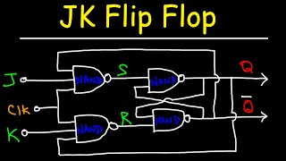
- For the circuit shown in the following diagram draw the waveforms Q0 and Q1. Note that the J-K flip flop is a negative edge triggered with active LOW CLR and PRESET inputs. Assume Q0 and Q1 to be initially 0.
An SR latch (Set/Reset) is an asynchronous device: it works independently of control signals and relies only on the state of the S and R inputs. In the image, we can see that an SR latch can be created with two NOR gates that have a cross-feedback loop.
SR latch is a bi stable single bit memory device, which is used in many sequential circuits for various memory applications like in bit wise registers and one more use in heavy electrical systems is in Debounce switch circuits
Other videos
8 KB direct mapped cache: size of memory needed at the cache controller to store meta-data (tags).
• 8 KB direct mapped cac...
Learn to indicate Hit and Miss in Cache Memory with an example
• Learn to indicate Hit ...
How the positive edge-triggered D Flip Flop works with PRE' and CLR' Inputs.
• D Flip Flop working wi...  Наука
Наука