How Does a Switching Power Supply Work 1 (schematic, explanation, example, modifications)

HTML-код
- Опубликовано: 30 янв 2018
- Part 2:
• How Does a Switching P...
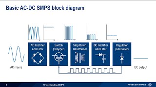
In this video I explain in detail how does a flyback switching power supply work. I show a SMPS from a DVD player as an example, I draw a schematic of it and I explain how does it work using this example. I also explain how you could modify a switching power supply output voltage and how to turn it into an adjustable voltage power supply (DIY bench power supply).
You can support me on Patreon:
/ diodegonewild
My Instagram:
/ savage_danyk  Наука
Наука


It is the best explanation of a SMPS working on RUclips 👍👍
Your ability to concentrate is inspiring.
Best SMPS video on RUclips... Hats off...
WOW!! I'm just a beginner and I completely understood everything you said, some of the math and how you got there is over my head but that is by far THE VERY BEST explanation of a fly-back PSU ever. I cant wait to see pt 2. THANK YOU for doing this.
Very glad I found your channel. You/re doing some of the very best electronics content on RUclips right now and you deserve a much larger audience. This video is the clearest explanation of flyback PSU operation that I've seen. Well done!
I agree. His components tour narrative and follow-up schematic analysis has demystified areas of the SMPS. Big thumbs up.
I ENJOY HIS VIDEOS BECAUSE HE KNOWS HIS STUFF. I ALSO REALLY ENJOY LISTENING TO HIS ACCENT... AMAZING!!!
I've watched this several times; each time a little more make sense. I'll have to watch a lot more times before I understand it fully but I have learned a lot up to now. Great video with excellent explanations at each stage.
Glad u are learning such archaic subject, but feel free to ask questions. This guy is good but he has omitted many key aspects of SMPS such as inductance of the flyback, stability criteria, efficiency calculations based on power losses.
Videos like this are what got me to support via Patreon, even though I don't have a job right now! I really enjoy learning through schematics explained.
I could watch this kind of stuff all day. Glad I found your channel.
I have been watching your SMPS videos for a year or so, you are the reason I have learned how SMPS works with detailed explanation from schematics, I have done some SMPS repairs with the knowledge I have gathered here. Not quite tried to create from scratch yet. Thank you for your videos.
Friend. Watch my video!
ruclips.net/video/2Qr6Jcm8wbA/видео.html
Excellent as always. I always look forward to a new video from you. Always interesting and entertaining.
We salute you the way of teaching and explaining, may GOD Bless you.
Absolutely fascinating. A great in-depth and concise explanation on the function of a smps.
really this is the best video i have ever seen before on youtube , please go ahead for more explanation
well done
I stumbled upon your video & at 1st i simply could not understand what you were saying but after a couple of minutes, i have to say HOW WRONG I WAS! Your explanation of SMPS is brilliant and i learned a some new stuff about the things. Love the way you used a hand drawn back engineering diagram and proceeded to trash it with all the info a symbol to just how complicated an SMPS can be... ! I've subscribed to your channel.
No One does it Like DiodeGoneWild...
Decided to wait 'till I had time to properly concentrate on this, glad I did. Lots of good info, thanks.
The genius you are Man.we love your videos.big salute from algeria
Damn great video. Thank-you-so-much, Dan, for explaining it so clearly. Videos like this are very useful because they're not just simple tutorial telling you how to do something, what to change, what to remove and so... such materials are much more useful. I almost feel how my knowledge and... understanding grows up! Thank you. :) Keep doing this, my man!
Greeting from Spain, I'm not able to describe how useful are your videos, thanks a lot
I think this is the best and detailed explanation of a SMP I found so far. Great work 👍
Friend. Watch my video!
ruclips.net/video/2Qr6Jcm8wbA/видео.html
DGW: love your narratives and schematic analysis. I have learned much from your videos.
Ok, but please keep quite. You don’t want to upset his cat.
Sir
You are a thorough genius.
You explain very swiftly
I am lucky to have found your channel
Friend. Watch my video!
ruclips.net/video/2Qr6Jcm8wbA/видео.html
I could tell by the thumbnail that this was going to be an excellent explanation of how a switching power supply works.
thank you for this video! i look forward to switching supplies videos but i do enjoy all your stuff.
you are the best teacher I have never ever seen before .
WOW! Thanks. I finally understand what you mean about the TL431 "turning on." Sorry if I misunderstood. I'm genuinely just trying to learn and understand this stuff myself.
I'm glad you mentioned that bit about the auxillary winding voltage. I hadn't thought about that one. I was mainly concerned with the secondary side components. The ones I've modified don't get hot or show problems, but as I tell anyone, I would never leave a modified supply powered on unattended.
Just now I looked at all of the switching supplies I've modified to look at the circuit. I'll still need to check the actual voltages but I will need to finish my current project first to make space. All but one of the supplies I've modified have a zener on the auxiliary circuit for the switching IC power rail. I haven't retraced them completely, but at a glance the circuit appears to be set up to clamp the voltage for the chip. I know the dissipation and voltage ratings are still vital, but the examples I have appear to compensate for auxillary power fluctuations to some degree.
I really appreciate you showing all of this. Honestly I got the idea of modifying the output of a switching supply after taking apart a Sony camcorder power supply that had a rating of 9.5volts. After taking it apart I noticed it had a trim pot on the secondary side. It's adjustment set the output from around 6 volts to around 18 volts. Later I came across another supply that is from a company called "Rhino" that sold a "Universal AC/DC Adaptor" model: PSNC-75M. It has a switch on the bottom that sets the output voltage at 12, 15, 16, 18, 19, or 20 volts. It actually rates the output on the label at:
12V, 5.4Amax DC
15/16/18/19/20V,
5A-3.75Amax
(That's an exact quote of the label)
I haven't torn it apart because I use it for an ancient laptop, but it also has an auxiliary USB 5V output rated at 2A which is super handy. After watching your video here I'm really tempted to take it apart to figure out the topology.
I've also been goofing around with the little adjustable supply I made the video about modifying awhile back. I'm trying to add a linear regulator to adjust the voltage lower, but I'm waiting on some dual pots in the mail as thats the only way I know of to adjust the switching supply and regulator to track each other without adding an op amp circuit. Any ideas or suggestions are more than welcome :)
BTW, could you put "flyback" in perspective please. I think I understand the basics, like the charge is stored in the core. I got a bit confused after reading that there are continuous and discontinuous types of flyback operation.
I have a hard time putting the different terminologies into perspective for the different switching designs. I think I understand buck/boost/buck-boost, none isolated/off line and those types of basics. I have a hard time understanding what is branding terminology versus topology after that point. I vaguely recall "Switch Mode Power Supply" is a branding term. I came across "Peak Mode" used to describe a controller/topology at some point early on in my exploration of these things. I originally associated that with the simple designs that use a single voltage feedback loop and a current sense resistor like a MC34063 etc. I thought of the dual feedback chips as "PWM" because the first time I saw a chip that was labeled as PWM was when I looked up a TL494. The first time I saw the term "flyback" was in reference to the high voltage transformer used on old CRT televisions, so I thought the design was more high voltage specific. I've realized this is incorrect, but I have a hard time understanding how it fits in to switching DC converter designs over all at this point.
I think someone with a thorough understanding should do a video on an overall abstract explanation of different switching designs that tries to cover 90-95% of the designs used regularly in practice. Maybe they could also explain the basic evolution of things like power mosfets and bjt's as it relates to switching IC designs. I know I hit a learning-wall when I discovered the output current limitations of the MC34063 for myself. I think it is due to the Darlington output design. IIRC I read somewhere that this design was done before power mosfets, and that's why it sucks, but I could be wrong.
Seriously, thanks again for all of your efforts. I recently noticed your website link in a video as well. I bookmarked so many pages I had to make a folder for it.
Very much appreciated,
-Jake
This is the Rhino psu mentioned:
s1160.photobucket.com/user/jakebikereligion/media/20170602_182031_zps24vdy4hq.jpg.html
This video benifits me more than a whole semester, thanks.
very very informative and excellent narration, thank you very much.
I've altered a few 19v laptop power supplies to 13.6v output. One didn't work properly when I reduced the o/p voltage, now I know why! Thanks dude :)
Loved it!! It was super interesting and informative. I'm subscribing. 👍
Thank you, Very informative. Gives a good understanding on how a SMPS works....
Love this channel!!! Cheers from Brazil
Awesome video ! Superb description of the circuit !!! Keep posting videos !!! 👍👍👍👍👌👌👌👌👌👌
Thank you sir. Perfect explanation of schematic circuit to design level.
Friend. Watch my video!
ruclips.net/video/2Qr6Jcm8wbA/видео.html
I would like to encourage you to keep making videos like this periodically. Even though it does not get the views of the simpler ones its important to add proper content.
I made a 5 videos on solar panel hobby project. Though it has very few views I am not daunted. It was really for me to put down all the info in one place and spend the time to consider all angles. I even picked up an error assumption I made in the second video when I did the calculations for the third.
Thanks :) I will definitely keep making such videos ;)
So much information in one video
You earned a subscriber 👍
Wow awsome lecture, very well explained no detail left out.
Excellent tutorial on smps ! Wow
If you haven’t yet....it’s time to subscribe. Great , in detail explanations.
You are an Electronics Master . Thank you for sharing your knowledge. Keep it up with this type of explanations. My motto is P.S.'s and electronics devices are designed and built from high knowledge people like you, Masters and PHds. Trying to make circuit changes on P.S. can be fire hazard. You guys can see how complex are calculations on semiconductors, I even see more complex equations and simulations. Please do not attempt to change main circuit. If you want you can add external DC-Dc converter.Namaste.
Excellent explanation and loud audible English
A brilliant explanation! And your accent is so cute :)
Sir I am from India and your explanation is very nice ...i can understand your complete english
I pulled several of these from throw aways and i test them. Its a good way to learn.
Great video! Thanks for posting I learned a lot here.
Díky moc za vysvětlení! :)
Beautiful explaination Hats of to you Thanks
Great explanation.thanks for sharing your knowledge. Your teaching videos help us alot.
Friend. Watch my video!
ruclips.net/video/2Qr6Jcm8wbA/видео.html
I really appreciate your detailed explanation
Love this guy's voice.
Like singing a song...
Thanks sir.. Clear and accurate explanation..
This is amaz ing how you explain it. Please do more Videos
Thanks :) more videos are coming...
Very helpful. Thanks for your time and knowledge
Amazing .. best explained on youtube
another great video
I Like all your video bro.superb explaination.gave u more thumbs up.
Thanks a lot for your excellent explanations .
Very good video Sir...
Very helpful...
U r a great teacher...
Great video. Waiting for video about half-brigde topology :)
Yes, that would be good. Most ATX PSUs are half bridge.
Great explanation :) Thank you for your effort .Cheers
Excellent video. Very informative .
Ah thanks greatly finally the 5v light came on with regards to something you explained thank you.
yes! this is it! I finally found it! thank you!
thank you indeed really thank you, your information is more helpful
Wonderful explanation !
Wow what a presentation!
Very good work, keep it up.
Best one description.thanks very much
thank you brother for these educative videos.. Weldon..
eagerly waiting for next tutorial on smps power supply
Thank you for your very much informative video more power to you brother.
Thank you so much. I am trying to repair a subwoofer amplifier with switch mode power supply. At least, now I know what the heck is happening!
Nice video, thanks!
You are Awesome and Inspiring!
thank you .. i have learned a lot from you ... master
Super Video Dude....
Keep it up....
Nice explanation. Go ahead.
Very good description
Very good explanation
Everytime i watch this video i learn something more! Really great and very deep explanation of switch mode PSUs in flyback topology!
So thank you very much for this excellent explanation!
I just have one question: why is the voltage per turn different in each polarity? Is it mainly because of different slope steepness when turning on and turning off (transistor/mosfet) as we know the change of current per time is relevant for the induced voltage? Or is it mainly due to the duty cycle as you explained? Or does both relate to each other so that it comes to the same result? Not absolutely sure about this?
Thank you very much for clearing my doubt❤❤😘 .
Excellent explanation,
Can you make an SMPS design in your future videos? It is not easy to find out core type, which turns are required etc.
Very nice explanation thanks
Great video - very well explained! Love it! Would be great to hear your take on why the outputs are not at the rated voltages (would this be linked to e.g. bad capacitors?)
very good explaining
very tanks
I have been binge watching your videos ever since RUclips recently recommended one of your small power supply videos to me after watching a BigClive video and yesterday and today was spent tearing down every single sketchy Chinese electronics device I have ever purchased!!!! Holy Fuck was there some dangerous USB chargers 🔌 with Class X2 1KV capacitors ACROSS THE MAINS AND IN A SPOT THAT WAS CLEARLY MARKED CY1!!!!!! I’m learning a lot about safety from your Super Sketchy Chinese Device Videos and my favorite part is always the reverse engineering with schematics and extremely in depth explanations of what each piece does and why you’re supposed to be using certain components specifically because of safety!!!!!
Super fantastic explanation sir thanks
EXCELLENT. Nothing more I can say.
What a great video!
Good my friend .l like ur videos .and ur explaine in electronic , ur voice so beautiful . continue
Great video!
Excellent bro !
Another power supply tutorial I gotta watch
Great video just found you and will sub.
owsome bro, loved it
Thank à lot for the sharing .Nice vid
👍🙏. Excellent. Congratulations.
If I could I would give you two thumbs up! Great explanation. Are you planning make some videos about ATX power supply?
I have already made a video about how does an ATX work:
ruclips.net/video/Cur3nQjjyyo/видео.html
And a video about how to repair it:
ruclips.net/video/HcYFbCqM61g/видео.html
Great stuff.
I did not understand what circuitry set the OFF voltage to 100V whereas the ON voltage could vary with mains?