5V 10A Power Supply Repair

HTML-код
- Опубликовано: 3 ноя 2020
- Please support this channel on Patreon and get early videos:
/ diodegonewild
The schematic and how does it work:
• Flyback switching powe...
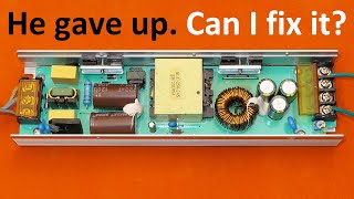
Today, let's see how to fix a faulty 5V 10A 50W switching power supply (SMPS). It produces strange sounds and the output voltage is unstable. I show all the important components on the circuit board. I identify and replace components that failed. I talk about the impedance (ESR) of electrolytic capacitors. I also improved the heatsink mounts of the power transistor and diode.  Наука
Наука


I don't understand a single thing about electronics and neither does any of the explaining tell me anything, but I find these videos incredibly soothing and relaxing. Anybody else?
You must sub to BigClive and Great Scott channels.
A lot of people like you are there.
I don't understand it, but who am I to stand in your way of happiness?
I've dreamed of such videos for YEARS...Namely, someone who would take an out-of-order piece of hardware and go through the board from the input to the output. I cannot thank you enough for your awesome content. I'm learning so much from you. Hats off to you
I would like to see more repairing video about power supply from you, you are such an expert in power supply I have learnt 80 % of my power supply knowledge from your channel and website and also tried to build my own power that was amazing... 👍👍👍👍 .. always amazing videos and thanks for sharing.. 🙂🙂
Very common fault on SMPS, you could show on oscilloscope the effect of a bad capacitors.
Thanks!
Can you check some "Super fast chargers" ?
For example the Huawei's "5V/2A or 9V/2A or 4V/10A" 40W SuoerCharger or something similar?
Good idea! With voltage current charts
Send it to him, or send him the money to buy it.
No?
@@piconano
I will send one when i get my salary. :)
40W??? Pfffff i have already seens phones with 60-80 chargers and there is even a 120W charger now. I really would like to see one of those or at least a oneplus dash charger or warp charger. Maybe in the future ;)
@@bashaaksema94 xiaomi mi 10 ultra
Good fix on the heatsinks. I've filed down the tabs on those before. Still for the price that type of power supply is one of the best deals out there.
Great video! I feel enriched when you take me through the thought process of troubleshooting.
perfectly described. I really love the narration. both the subject and the accent. a true "engineer"
a minute ago i was thinking about you and badam!! you just posted this video!
You're in love!
@@midimoog not that way, my fellow man
You tube has developed a way to enable the emotion and thought sensor in your device to activate a new algorithm and send that feed thru.
i always wondered about the X class capacitors and the Y class capacitors and when you would use them.
i know you use a Y class between the hot and cold side of a power supply. so im glad i know now.. THANK YOU DANYK!!
I find the old terms most descriptive, "across the line" (X) and "line to ground(potential user contact)" (Y).
No one explains PSUs like you. Excellent!
April 1st idea: repair some devices sent by viewers, then put them back together as good as you can, and then initially present them as actually working and you having no idea why were they sent as broken or something. You could then actually show the repairing and all :D
Excellent video! I have also just same esr meter as you have. It's really handy. My humble thanks.
You are the best professor with power supply. I love that type of video
Soon as you removed the cover, I saw that it was the capacitors.
You, my friend, are the best!
Great fix. That one's a keeper.
Very informative video, thank you for posting it.
Would it better to overflow, or have a perfect amount of Thermal Paste in order for it to work the best ?
thank you for these videos they are very entertaining
Thank you for your RUclips Channel, I have learned a lot from you.
Nice repair video
I like videos diodegonewild, Keep up the good work :-)
good notice on transistors mounting brackets.
Excellent episode. THANX
I have collected lot of Capacitor from old circuit board : Nippon-Chemicon, Nischicon, Rubycon .
Would i throw them ? Please Suggest me .
Love Your videos!!!
Could you maybe make a video series about making homemade SMPS and explain every aspect of the design, component choice, transformer construction etc.? I think it would be super interesting and very informative. Your tesla coil videos encouraged me to actually finally build one, because before I wasn't sure if I knew and understood everything. You explained every part very thoroughly and I learnt many things for sure! So, what do you think?
Try
ruclips.net/user/KasyanTVvideos
This guy does a lot on switching power supplies.
@@therealjammit Thank you!! This channel is most interesting!
I wish I was so lucky that my repairs would have such an easy solutions. Last time I repaired similar power supply there was a problem with switching IC and burned resistor.
Sir can you make a video on how you design snuber networks for you Hv circuits I would really appreciate that and I am also confused about the resistor values when designing circuits like a pre amp for feeding modulated sound in sstc circuits...
Any help is really apprecited
Regards
can you discuss about x and y safety capacitors. how does it provide what is says it does?
Nice video, very well explained, as usual. 🙂
But smoothing capacitors do not see high frequencies. For these its more accurate to measure on their working frequency of 100 Hz.
Super cool, Im a Fan of you👍👍👍👍👍
Thanks! I learned something new today. ⚡️👍🏻👍🏼👍🏽👍🏾👍🏿⚡️
I was curious if we can convert a flyback smps supply from 0-12 volt.. The minimum i got was 3.3 volt but i need 0-12 volt... Is it possible i can give external supply to main switching control ic ... Will tl431 and other circuit work with it ??? Share your views.... It would highly appreciated... Thanks.
The main capacitors after the rectifier are serialised. I read 220uF 250V. It gives 110uF.
E=1/2.C.V2
Usually there is only one having U=400V
Thanks for the great videos!
Do you have to remove the capacitors from the PCB in order to use the ESR tester? Did you do that for accuracy?
You mostly don't have to remove the capacitors. It uses a low voltage at a high frequency (100kHz) for the test. Inductors in the circuitry have a high impedance for 100kHz. Most semiconductors have a higher voltage drop than the test voltage. Most resistors in the circuit also have a much higher resistance or impedance than the capacitor. The only exception is capacitors in parallel. You can't test individual ones in the board. But parallel capacitors often fail all, because they are the same batch. And also because if one fails, the other ones are loaded with more ripply current, so they soon fail to.
2:39 is it good to power both filaments at the same time?
Hi, i have a pascal 540w atx and when i load it voltage drops to 9-10v!
I don't know what's the problem and how to fix it.
What is the problem if Output LED of SMPS is flashing on and off 1 second?
good job nice work succes my friend
Nice video and the obvious Capacitor failure, nice advice on the modification of the metal holders for the transistors :-)
Hi Fred !....squeak!
@@andymouse Hi Obviously the mouse traps are not working:-)
@@fredflintstone1 Nope !!
@@andymouse Damn next you will tell me you don't like Cheese:-)
@@fredflintstone1 I prefer Peanut butter ...but I am a sucker for a piece of Roquefort !
I have a question, hope you will reply.
Where did you buy that esr meter?
Do you have link?
Thanks for good video
Unique human!
How would I go about building a 2kw 100v dc power supply? Does rectifying one of those cheap SCRs work? Or is the power at lower voltages limited? I live in a 230v area. Maybe you guys can help me out. Thanks in advance!
2KW/100V is 20A. Thats huge. Building one would not be easy. Probably easier to rewind a couple of microwave transformers and rectify the output.
@@simontay4851 thanks for the idea! I didn't even think about transformers
Thank you for your suppoRRRRRRt
Very nice!
I was planning to build a tesla coil with a High frequency driver like you have a while ago
I built one and I have to say, it's a pretty neat driver. It has its limitations though. But definitely go for it if you want to!
@@drobotk (im the same person who has posted this comment on a different account) yes i could do so and I hope it goes well in the future :)
Did you notice the spark coming from your power strip when you tested the power supply with the light bulb for the first time (2:20)?
What is the risk of running such power supply without a load (if that loading resistor was not present)?
Can you please take apart the new apple 20w charger? Lots talk about it online.
I have a 12A one and it emits high frequency sound too, it depends on the load too.
Can u sir explain about your watt meter its look like normal multimeter its a special multimeter u have made or if not than please give me a link of that meter so i can buy
danyk.cz/wmetr_en.html this is built into the power strip, plus an extra 3.6 ohm resistor goes in series with the 0.4ohm to make it 10x sensitive in the red socket.
plz make a video on current flowing LED Indicator, i want to use in my battery charger, when i connect the battery LED Glow up to show its charging, and after disconnect the battery from charging LED Must be turn off, plz help (LED Should be glow stable and should not fluctuate )
0:50 ... electrocuution - dat soundez interestiiiing :D Just like everything he says.
HEY DIODEGONEWILD! I found a 12V 50A power supply on Ebay for less than 40$, which is incredibly cheap for the power! But isn't 600W a little bit too high for a halfbridge power supply, or at least without active PFC?
I would really love a testing video of this power supply!
Bloody Hell, good job.
Lols
Hmm not much controlling the supply, reminds me of the cheap 12v and 5v bricks used for powering hard drives.
One mosfet and 2 transistors and an opto coupler.
When that supply was switched on and the tone came from it, i though Crap-a-ctors lol.
I did not expect the primary 400v caps to be worn out, and they were not.
It would been fun to actually know how much capacitance was left in these caps as well, as capacitance usually drops when they go bad like this. the capacitance was likely just a few percent on top of the higher ESR and the combination made the thing fail. I saw the caps 2 seconds after the cover was released and expected to see them even before you took the cover off considering how the supply was operating
I like your effort to reverse the circuit board because it s not easy.
Anyway, you did not represent the feedback coming from the transistor of the optocoupler. It should return some Peak currents accordingly to the output power demand from the secondary.
I can hear a very high frequency when you test the psu after fixing and having the load.
I suggest you to try the app phyphox. There is a cool audio FFT spectrum analyzer.
You could show us that the frequency is depending to the output power demand.
Merci 👍
You saying the word "ridiculus" sounds like some spell from Harry Potter :D
awesome
what drives mosfet if there is no driver ic ??
There is no MOSFET, it's a BJT transistor :)
We'll need to see the next video to be sure but my guess is a feedback winding on the transformer drives the main transistor with positive feedback, similar to a 'Joule Thief' circuit.
Nice
Awesome
Please do a video series for LCD LED tv's repair
Hi sir good day.. My ender 3 3d printer psu stops working. There is only around 6volts in the output and the light is half lit.. Can you help me fix it.. Thank you
And one more thing. There is no blown parts. Transistors are all good. There is no vcc in az7500ep ic.
I have the exact same printer and problem
Nice, Please make video on Diesel engine Generator AVR reverse engineering schematic please.
15:41 were does the sound come from when plugged in?
I think it is that transformer first struggling for the high inrush current of those lamps :)
are transformers the only parts in electronic circuits, that produce sounds? (despite speakers obviously)
Transformers are known for their humming it is the cores of the transformers
Ok but like caps and other electronic parts don’t emit sounds?
@@suncrafterspielt9479 Those capacitors which had a hole in it also can make a sound but it is very rare because it needs a lot of pressure
Good night
Love from India
Please, do more power supplies, hardware, motherboards, and expansion cards repairs/fixing.
Also, I would like to ask, how long can stay capacitors charged, and be dangerous for health, in :
Power supplies for computers.
In CRT monitors.
Is it in days, weeks or months?
good
When the video will come?
Could you maybe also explain in the next episode why sometimes ultrafast recifier diodes are used? As far as I remember, in ATX PSUs the 3.3 and 5V rails are mostly rectified using Schottky diodes, whereas the 12V rail almost always is recified using ultrafast rectifier diodes.
Shottky diodes tend to have a lower voltage rating. In ATX, the 5V rail has about 24V peak reverse voltage on the diodes, so a 40V schottky with a low voltage drop is used. The 12V rail has about 56V peak reverse voltage on the diodes, so they use an ultrafast diode rated 100 or 200V, but with a higher voltage drop. Couple decades ago, Schottky diodes went up to only about 40 to 60V. Now there are 100V or even 200V schottky diodes, but they have a higher voltage drop than the 40V or 60V ones. A 200V schottky probably has just a little lower voltage drop than a 200V ultrafast diode.
My ears are well trained, before he opened the housing I could hear capacitors "screaming".
to me You are just like Tesla. You are amazing. A++++++++++++++++++++
I have A New Power supply with a sound only when there's Very low power. But as soon as I get more power for example my LED Light Strip it no longer has Noise.
One other problem is when using extreme power changes for example my LED's flashing very fast and at. Different rates of speed the Noise comes. Back maybe even louder.
Last issue is that I find that after 12 hours the Noise will stop when used at low power. Then I turn on the LED's and turn back off. So it uses more power then goes back to a small amount of power the Noise is back as if I just plugged it in.
Zdravím, rád bych něco přispěl na teardown. Je nějaká adresa kam můžu něco poslat?
Díky zdraví Jara.
Love your accent , from what region or country that is?
What do you think about this design since there is not a SMPS chip?
Actually, i was expecting a chip on the other side of the circuit board.
Do you have
I will measure the no load consumption (and maybe also the efficiency) in the second part ;).
no need to draw the the schematic, you can download one from here: sxem [dot] org/2-vse-stati/19-istochniki-pitaniya/114-impulsnyj-blok-pitaniya-12v-5a-3a-1a
it's S-60-12, your S-50-5 is the same but the transformer, LED resistor, 431 resistors and R10+C7 part
Thanks :). There are several more components with different values, but otherwise it's the same thing, probably on the same board.
@@DiodeGoneWild yep, the board is the same, plus-minus (different revisions?)
I think they recycle some components to make this PSU cheap. That's why values may vary from one unit to another. Anyway, this is the best simple low-power design I have ever seen in chines PSUs. It has all protections, filters, snabbers and fine tune. For best results it's god idea to replace optocoupler, both transistors and 431 -- who knows about the quality of those parts?
Grate
@16:00 Why don't they connect a Schottky diode to the ground, instead of across the coil in a snubber RC filters to dissipate the recoils as heat?
That way, the spike pulses (recoils) can go back to the main supply caps through the ground plane, and the spike's energy recovered. Minus the Ohmic losses of course, which would be about 3% tops. That would make the power supply 97% efficient! Theoretically of course.
It will be electrically noisy and will throw RF of course.
But could that not be handled with the right metal enclosure to act as an RF shield?
If I can do it to a pulse DC motor, why can't I do it to a transformer?
Please consider this questions for your next video.
make more vids about switch mode power supplys
Na těchto průmyslových zdrojích je dobré, že mají trimmer, takže lze pohodlně vykompenzovat úbytek napětí na vedení, jinak upřednostňuji zdroje na PCB, co číňani kuchaj z vyřazených spotřebičů a střílí to na ali za pár dolarů.
👍
The caps fail more so in SM supplies because of the high frequency. Linear supplies live forever.
Well nothing is perfect haha!
Not "forever", but I've seen some 50 year old ones work fine with no excessive hum (ripple)
@DiodeGoneWild -
Oh this is dso clear , "pregnant" capacitors on secondary are 100% faulty , my cheap 400W PC- power supply (Intertech COBA [heating brick]) failed the same way after 5 Years of only low load (because I planned for a much more power hungray grafics card that I never bought)
👍👍👍👍👍
But why this supply has to switch between 110V 220V even though it's just 50 Watts, flyback power supplies are good up to about 120W 130W , over that power, you need to manually switch the Voltages.
Maybe it's just the design probably.
Jinak ten zdroj je out, některé elektrolyty jsou viditelně "rozkvetlé".
nechapem, ci si nepozeral video, alebo naco je ten koment. Ved ich vsetky vymenil. Nabuduce pozri video cele.
Was anybody else _concerned_ by the bogus compliance sticker on the motherboard?
*ROUS* instead of *RoHS* caused me a long sigh...
niiiice
This is probably one of the worse copy of a older MeanWell supply. The components are not good quality & the big caps are probably Nippon Chemicon knockoffs. Even the fake RoHS sticker has been copied incorrectly & instead says ROUS.
However, excellent video & explanation. Keep up the good work.
I was also thinking about the ROUS sticker :D. I wasn't sure whether they mean RoHS or it's something completely different...
The big caps probably are true Chemicons reclaimed from E-Waste. If I'm reading correctly they seem to be datecoded 41st week 1993.
@@cossasomi This may be very true but reclaimed caps are even more dangerous than knockoffs. God knows what they have suffered before. Hope some testing was done before reuse.
Atleast some of the e-waste is being reclaimed rather than going into landfills.
@@DiodeGoneWild Still better than those O.K Tested stickers. Haha....
I think they had to test them before use. Having to rework the board later on would probably wipe out all the money (and then some) they saved by using reclaimed parts in the first place.
I love to hearing that heeeeeere heeeeere❤️❤️
thadits nyyyyyyiice
Did you really discharge the 400V capacitors before to measure them ? You could have 318v for hours ...
There are discharging resistors in it, and I checked the capacitors are discharged.
@@DiodeGoneWild good boy ! ;)
Hahahahhahahaa i misses this voice way back 5yrs ago..
Your cat doesn't accept it because he hasn't been seen :)
S60SC6M masfett