Your presentation style, your english pronounciation & of course the way you torture the equipment during your testing are unique on you tube. No other youtuber has these qualities. We love you.
You are absolutely crazy if you have made a schematic to it, even if it had some mistakes... I'm quite impressed of your knowledge and patience, despite from the fact that I've been your regular viewer for over a year... - greetings from Poland! P.s Keep doing what you do! Your cat is absolutely cute! Congrats for 100K subs.
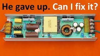
Bloody HELL!! :D Well it's obviously an assembly error, whether it's manual or automatic. But what's really troubling is that it has supposedly passed QC yet Diode has clearly shown us the specs were out of whack (ex. the higher than normal standby power consumption), which leads one to believe that there may not even be quality tested or maybe just random ones only. Oh the one legged cap... they've tried to save some colder... tsk-tsk
At 17:59 we see his beautiful cat - an important part of his success :-) And being a virtual rocket scientist of electronics, this genius fixed several problems. Fascinating. ' -_- '
I definitely plan to rewind the inductor ;). I also plan to rewind my vintage frequency meter. The problem is that I left my transformer wires in a different location, so I can't do it until I pick them up.
@@DiodeGoneWild Maybe trying to beat 90% efficiency by modding (well, fixing really) it further would be a nice challenge? :D Hardcore mode: using only scrap parts!
Thanks for another interesting explanation, you certainly help my knowledge of switch modes ! Congratulations on 100,000 subs, well done, I am working on getting there, I guess I need to do more educational types of videos rather than just repairs and reviews!
Congratulations with 100 000 subscribers, DGV. As far as I understand youtube, you are doing the right things. Such as ... uploading regularly. Interesting content. And you put alot of time into your videos. Even if you understand electronics very well, it takes some time to reverse-engineer circuits and draw those schematics that you do.
i fix my 2 years dead power supply 24v 20amps and now working perfect again i have zero knowledge but this video is perfect thank you for this video !!!
Very witty course in working and troubleshooting of SMPS. Very smart man, and he explains very well. He addresses every fact well, and he is not boring. Excellent. BTW, in this lab, the cat should be placed in charge of ESD protection of all MOSFETS.
Always love your explanation about power supply, you had a great experience with huge knowledge in supply and your ckt diagram help me a lot many times, Multimeater, and supply diagram, too
I like your content because of step by step explanation of each part and you uses all conventional stuff for measuring. I'm always waiting for your switching power supply videos. Because it's grate and I learned many things from you. Thank You for those kind of videos.
Great video, I am looking forward to see your schematic explanation because I have the same power supply in 12v/15A version with problem. I measure 12v on the output with no load connected. When I connect a load It collapsed . I believe your schematic analysis will help me to figure out the fault.
you got it! when I used to work on old TVs and I touched the flyback circuit I would flyback all the time. Thank god those Boob tube tvs are gone now. flat screen tvs are alot safer
I am absolutely astonished by your power meter made out of a multimeter. It is always convenient to have a small device on hand to check things. Is it possible for you to uncover the working principle and circuitry to all of us? I really love this modification.
Very informative. Thank you for very detailed explanation. Today i've repaired my LED PSU - one capacitor was blown. It's better to repair then buy new and put broken to trash.
Thanks this was one of your best uploads yet. I have a list of things to characterize and test on a similar power supply now. I've been working on a large LED bench light for ages and planned on having temperature and power monitoring. I keep letting too many features creep into the project (clock/room temp/LCD/menus/single button with multiple functions/watchdog timer/etc). I guess I'm still too stupid to "Keep It Simple *." ...anyways...now I want to add mains current sensing to monitor efficiency too ;) Thanks for the upload. -Jake
Fantastic video, thank you so much for sharing, had not thought about winding an extra winding for the scope, realy nice idea. I have used a little inductor held close to the transformer, coupled to the scope before, to determine if the transformer was switching, that also works, but you dont get the correct waweform, only to determine if it is switching. Looking forward to the explanation video. Greatings form Denmark
Excellent! I have one more idea for you to try: that little slope on the primary waveform when transistor turns on is most likely caused by snubber network. It is too agressive, increase R or reduce C. Should be able to gain an additional percent or two for the efficiency.
@@kwpctek9190 Doing that will decrease so called copper losses ( it doesn't have to be copper, effectively it is winding loss). Copper has smaller resistance than Al, so the power dissipated on the active resistance of the winding is gonna drop. It is I^2R, by decreasing the resistance in half, you will halve the power dissipation.
@@kwpctek9190 Much more power in this case is dissipated due to wrong amount of turns, which Danyk fixed. By putting too few turns you will get giant hysteresis loss (the core of the choke will saturate, this will be followed by increased ripple on the output).
@@mrjohhhnnnyyy5797 Exactly, and the wire was copper clad, so skin depth at ~72-kHz would be under 350μm. Hey, when is Mr. Johhhnnnyyy 's next video? *☺☺☺☺*
@@mrjohhhnnnyyy5797 that he did is not proper fix it is just bodge, his fix could easy turn smps in high power oscillator, output indicator affect open loop transfer function of smps and that affect close loop stability, so after changing output inductor you usually need to at least chack stability and sometime redesign control loop.
Great video. I use these for ham radio equipment usually 12 volts 50 amps. I had a 24 volt one to at 25 amps. A couple have gone BANG & they were not being over driven. For the price they're good but some are noisy on radio, some not.
Great video and awesome repair. and congratulations on 100,000 subscribers you deserve all the rewards that come with the hard work you you have put into so many videos.......
I love the way you fixed that transformer soldering iron. I have dozen of these and they seem to be indestructible apart from the threads in the copper bars that give up after tightening couple of times...must try that
100k suscribers, bloody well done!!! Your chanel has taken an up-swing, I believe you can become much more popular, especially if you make videos about interesting devices like this PSU for example! You may also want to add a means of contacting you for people that may want to sent you a device to analyze/fix/make a video about! Keep it up!
The R1 and R2 across the primary smoothing capacitors are not for discharging them, but for making sure their voltages are divided more evenly as they are in series and their small leakage currents would eventually make them unequal. The resistors basically have a current through them that is a few times larger than the capacitors leakage current, and they act as stiff voltage dividers compared to the leakage currents.
You are great 😁👍. You take so much time, to describe everything, so we can understand and going step by step... OFCORSE we can not forget your trusty sidekick THE CAT 😺. Everyone, have amazing day 😎💛
Very interesting it was good to see they put the suppresion caps and choke in it so often they get left out so at least they got that right! The error with the little cap having both leads in one hole was totally unaceptable I'm guessing they have no quality control congratulations on 100 000 subscribers that must feel awesome. Finally your cat needs her own channel
Wow, you really know your stuff. Plus the soldering gun and the Russian CRT oscilloscope reminds me of my secondary school practice in TV repair shops in what was then Yugoslavia!
Regarding the output inductor, I think skin effect will be heating up the wire as well. At 25 kHz skin depth is about 0.4mm so any wire above 0.8mm dia is basically useless. Something to think of when/ if you rewind the torroid.
I'll make it clear, I love your videos, mainly because of the amount of information you provide on the subject of the video, it seems to me that there is no lack of details (it must be a little stressful to make videos like this). Maybe one day consider testing a Brazilian power supply that is one of the best in Brazil (brand: Spark Usina), I recently acquired one and wanted to know about its quality and if it is efficient and does not waste a lot of energy due to the power factor.
Recently I've ordered similar psu, but 12x15, looks like they're identical. But hot-side transistors are in insulated packages and capacitor connected properly, board is identical and looks like inductor winded with non-copper wire too.
I can learn everything I want from you! the halfbridge PSU design is super fascinating, normally in professional PSU's (like a quality TV set) they will be at super high frequency using Litz wire and a smaller capacitor. it is pretty robust that it doesnt explode because one of the transistors died.
Ridiculous accent, but very good knowledge and understanding of electronic circuits with all the needed details put on display. Great job! I'm subscribing. Greetings from Bosnia!
I remember Stefan Gotteswinter saying that Chinese tools were fine AS LONG AS you treat them as "a kit of parts" and are prepared to do a bit of work to finish them.... this certainly seems true of this PSU too. Once you've fixed the miswired cap and replaced the "fraudulent" indicator and lost a couple of transistors to testing, it should be OK.
In the 2nd video, will we see output voltage and start-up trace from the main trafo? (ie: "soft-startup or when Vcc is cut from the TL494). This should show that 0.5vdc on the output terminal means self-oscillation works, but control circuit has failure.
I have some reasons to see your videos. Most important, it´s very interesting, it´s easy to learn more about switching power supplies, and further, i like the cat :)
I have to upgrade two of this brand/power PSU abaut 10 years back for an custom PC. One for a CPU section and one for a small DC-DC to do 12/5/3.3/-12 Volts. The goal is isolating the main noise source from sensitive parts, olso aviod the current loops at a main board. The base drive capacitors are best to replace an block-foil ones like 4u7/50V to get decent on/off shapes. The secondary inductor is olso seems to be gets saturated at 1/3 of their rated, the caps after starts to run realy hot. I replaced it an real one. Then the capacitors and semiconductors olso replaced with real ones, then it runs cool without any heatsinking at 20-30W load. The last thing i replace the NTC with an power resistor to get inrush protection when the line power is outs for a cuple of seconds, then shorting this resistor with an relay when the output is present. I think the biggest thing can done for this PSU load behaves is add tons of pure ohmic pre load. If i remember correctly its have to draws abaut 330mA. It is more than ten times higher than factory set! if the cat gets inside, the paper gets outside the new content will take much less care abaut the old content.
This guy speaks like a salesman in a department store trying to convince you something 😁 But man your a legend! Great review and your techniques are different and awesome! I just ordered online one of these psu to use it for my old cordless drill with step down buck conventer to 9.6-10v. Is this ok? Do you recommend to use a fan for cooling aside from changing the thermal compound of the transistor chips? Thanks man! more power to your channel 😊
Nice! I wonder how high you could push the efficiency by replacing those transistors with higher quality ones (lower ON resistance and shorter ON/OFF transition time).
Dear Sir like the way you troubleshoot and explained. I too have same smps 240 volts to 24 volts . But output is coming only 6 volts. Which part should check


It's a combination of intellect, dry humour and your English that makes you unique and brilliant! A pair of thumbs up
We need more of those comments :)
"You've got to be kidding me, guys."
It's is trrrrruuuuueee
Your presentation style, your english pronounciation & of course the way you torture the equipment during your testing are unique on you tube. No other youtuber has these qualities. We love you.
I forgot to mention your cat. Quite cute one.
You are absolutely crazy if you have made a schematic to it, even if it had some mistakes... I'm quite impressed of your knowledge and patience, despite from the fact that I've been your regular viewer for over a year... - greetings from Poland! P.s Keep doing what you do! Your cat is absolutely cute! Congrats for 100K subs.
Ķ
The bleeding resistors on the main caps also act as a voltage divider to make sure the voltage is nicely divided over the capacitors in series.
That's right :). Otherwise, the voltage may not divide properly in case the capacitors have significantly different leakage current.
Quality job there from the factory, I never realised china had invented the one-legged capacitor... :P
twocvbloke That’s really amazing!
Works great. Infinite breakdown voltage, and the capacity doesn't matter. Brilliant!
Electrictronic
Bloody HELL!! :D Well it's obviously an assembly error, whether it's manual or automatic. But what's really troubling is that it has supposedly passed QC yet Diode has clearly shown us the specs were out of whack (ex. the higher than normal standby power consumption), which leads one to believe that there may not even be quality tested or maybe just random ones only. Oh the one legged cap... they've tried to save some colder... tsk-tsk
You get what you pay for!
Congrats on 100K
Thanks :)
@@DiodeGoneWild Hey ;)
At 17:59 we see his beautiful cat - an important part of his success :-)
And being a virtual rocket scientist of electronics, this genius fixed several problems. Fascinating. ' -_- '
Wow....... I love it ......what an English...so pleasing. Impressing tone you have.
Can you rewind the inductor with copper wire and see what effect that has? Great explanation of the problem.
I definitely plan to rewind the inductor ;). I also plan to rewind my vintage frequency meter. The problem is that I left my transformer wires in a different location, so I can't do it until I pick them up.
Cool I am looking forward to seeing the video you make. Great video as always
Perhaps a better core as well
@@DiodeGoneWild Maybe trying to beat 90% efficiency by modding (well, fixing really) it further would be a nice challenge? :D
Hardcore mode: using only scrap parts!
@@uK8cvPAq sure - we can try it once you take it out of your arse!
also - the wire would be too thin.
U just have to love this guy's accent or what?. And his knowledge is huge.
Capacitor gone wild 😂😂😂
Congrats DiodeGoneWild 👍👍 💯 💯
More like the inductor coil gone wild... getting hottt!! he-he
2Legs1Hole
Hello there can you make a wall lamp with angle control and display different shades!!! ruclips.net/video/bUFwJuKF4eI/видео.html
24:42 I can't imagine you made it.
25:17 Still you are underrated. You deserve more. Or maybe only smart people subscribed you. ;)
By watching him touch components of an live power supply I assume he's a professional.
Thanks for another interesting explanation, you certainly help my knowledge of switch modes ! Congratulations on 100,000 subs, well done, I am working on getting there, I guess I need to do more educational types of videos rather than just repairs and reviews!
Down unda! You have a great channel too! Have you ever watched SMPS channel called MrJohhhnnnyyy ?
KW PCtek - thank you. I haven’t heard of that channel before, I will have to take a look
Congratulations with 100 000 subscribers, DGV.
As far as I understand youtube, you are doing the right things. Such as ... uploading regularly. Interesting content.
And you put alot of time into your videos.
Even if you understand electronics very well, it takes some time to reverse-engineer circuits and draw those schematics that you do.
Thank you, Diode! Congratulations on100K subs!
Looking forward to schematic explanation. Especially TL494 working principle.
Dane, ty jsi neuvěřitelný - srozumitelné informace i pro absolutního neumětela zábavnou formou, trocha, tedy i více šíleností. Díky za videa.
i fix my 2 years dead power supply 24v 20amps and now working perfect again i have zero knowledge but this video is perfect thank you for this video !!!
Very witty course in working and troubleshooting of SMPS. Very smart man, and he explains very well. He addresses every fact well, and he is not boring. Excellent.
BTW, in this lab, the cat should be placed in charge of ESD protection of all MOSFETS.
Always love your explanation about power supply, you had a great experience with huge knowledge in supply and your ckt diagram help me a lot many times, Multimeater, and supply diagram, too
Congratulations for 100k subscribers
I like your content because of step by step explanation of each part and you uses all conventional stuff for measuring. I'm always waiting for your switching power supply videos. Because it's grate and I learned many things from you. Thank You for those kind of videos.
Excellent video. Congratulations for 100k subscribers! Thank you for your work!
Great video, I am looking forward to see your schematic explanation because I have the same power supply in 12v/15A version with problem. I measure 12v on the output with no load connected. When I connect a load It collapsed . I believe your schematic analysis will help me to figure out the fault.
in the first 5 seconds I was sure you were russian... but then I heard how you spoke and I started grinning like I was crazy...
subscribed!
What makes it a flyback is that when you open it and touch a live part you will fly back
Lmao, your RUclips handle says it all!!!!!
My hair used to fly back every time I touched that darn flyback coil, but now there's nothing left to fly back, it all flew away forever. he-he
you got it! when I used to work on old TVs and I touched the flyback circuit I would flyback all the time. Thank god those Boob tube tvs are gone now. flat screen tvs are alot safer
I am absolutely astonished by your power meter made out of a multimeter. It is always convenient to have a small device on hand to check things. Is it possible for you to uncover the working principle and circuitry to all of us? I really love this modification.
That's why I like your channel and watched all your videos. This video was so informative and useful for me. Thank you.
Very informative. Thank you for very detailed explanation. Today i've repaired my LED PSU - one capacitor was blown. It's better to repair then buy new and put broken to trash.
Was beginning to miss your videos. Enjoy your videos very much!
100K? Those youtubers are growing so fast T__T. Good luck with 1 million.
I need REALLY a lot of good luck with 1 million ;).
Thanks this was one of your best uploads yet. I have a list of things to characterize and test on a similar power supply now.
I've been working on a large LED bench light for ages and planned on having temperature and power monitoring. I keep letting too many features creep into the project (clock/room temp/LCD/menus/single button with multiple functions/watchdog timer/etc). I guess I'm still too stupid to "Keep It Simple *."
...anyways...now I want to add mains current sensing to monitor efficiency too ;)
Thanks for the upload.
-Jake
Fantastic video, thank you so much for sharing, had not thought about winding an extra winding for the scope, realy nice idea.
I have used a little inductor held close to the transformer, coupled to the scope before, to determine if the transformer was switching, that also works, but you dont get the correct waweform, only to determine if it is switching.
Looking forward to the explanation video.
Greatings form Denmark
U explain much better than our prof. do. Thank U very much
Finally New video. I Waited for it so much. :)
Excellent! I have one more idea for you to try: that little slope on the primary waveform when transistor turns on is most likely caused by snubber network. It is too agressive, increase R or reduce C. Should be able to gain an additional percent or two for the efficiency.
MrJohhhnnnyyy - One of the other great SMPS brains on RUclips!
Question sir: What will rewinding that hot output inductor with copper do?
@@kwpctek9190 Doing that will decrease so called copper losses ( it doesn't have to be copper, effectively it is winding loss). Copper has smaller resistance than Al, so the power dissipated on the active resistance of the winding is gonna drop. It is I^2R, by decreasing the resistance in half, you will halve the power dissipation.
@@kwpctek9190 Much more power in this case is dissipated due to wrong amount of turns, which Danyk fixed. By putting too few turns you will get giant hysteresis loss (the core of the choke will saturate, this will be followed by increased ripple on the output).
@@mrjohhhnnnyyy5797 Exactly, and the wire was copper clad, so skin depth at ~72-kHz would be under 350μm. Hey, when is Mr. Johhhnnnyyy
's next video? *☺☺☺☺*
@@mrjohhhnnnyyy5797 that he did is not proper fix it is just bodge, his fix could easy turn smps in high power oscillator, output indicator affect open loop transfer function of smps and that affect close loop stability, so after changing output inductor you usually need to at least chack stability and sometime redesign control loop.
Great video. I use these for ham radio equipment usually 12 volts 50 amps. I had a 24 volt one to at 25 amps. A couple have gone BANG & they were not being over driven. For the price they're good but some are noisy on radio, some not.
Great video and awesome repair. and congratulations on 100,000 subscribers you deserve all the rewards that come with the hard work you you have put into so many videos.......
Your cat is sooo lovely! Thanks for testing the power supply, btw.
Congratulations for 100k subscribers!
Thanks for all the great video's of SMPS's .I have learned quit a bit from you. The fear of working on them has been removed, THANKS
Thank you so much for your time and Diligence for producing this video.
I love the way you fixed that transformer soldering iron. I have dozen of these and they seem to be indestructible apart from the threads in the copper bars that give up after tightening couple of times...must try that
100k suscribers, bloody well done!!! Your chanel has taken an up-swing, I believe you can become much more popular, especially if you make videos about interesting devices like this PSU for example! You may also want to add a means of contacting you for people that may want to sent you a device to analyze/fix/make a video about!
Keep it up!
I am so glad that your cat is an artist.
Love your videos. I think you explain and diagnose problems way better than Dave Jones.
The R1 and R2 across the primary smoothing capacitors are not for discharging them, but for making sure their voltages are divided more evenly as they are in series and their small leakage currents would eventually make them unequal. The resistors basically have a current through them that is a few times larger than the capacitors leakage current, and they act as stiff voltage dividers compared to the leakage currents.
Waiting so long for this. Just want to buy something and send it to this guy :)).
You are the best teacher ever,thanks my friend❤️❤️❤️❤️❤️
You are great 😁👍. You take so much time, to describe everything, so we can understand and going step by step... OFCORSE we can not forget your trusty sidekick THE CAT 😺.
Everyone, have amazing day 😎💛
Sir, execellent test, fault detection and improvement. Congratulations!
I love how you give the viewers a breath by incorporating your cat into the video
Yey many series love your channel
Outstanding video, love smps videos, congrats for 100k subs!!!
Great explanation , Congrats on 100K
Congratulations on reaching 100k subscribers!!! 🎉🎉🎉
Analysis and explanation of very high level. Big thanks
Congratulations for you 100K subs !
The only youtuber for witch i turn off adblock.
And also the sound :D
Another very interesting video with a lot of useful info, thanks. That 4.7uF @ 50v was unbelieveable.
Congrats for the 100k subscribers!
Congrats on 100k subscribers
You're killing me! :-D I've never seen the both capacitor leads in one hole mistake before! :-O
First time for me also... that is just... 🤣🤣🤣😂😂
Very interesting it was good to see they put the suppresion caps and choke in it so often they get left out so at least they got that right! The error with the little cap having both leads in one hole was totally unaceptable I'm guessing they have no quality control congratulations on 100 000 subscribers that must feel awesome. Finally your cat needs her own channel
In my 45 or so years of dealing with electronics, I have seen some strange situations..but I've never seen anything like that cap situation. LMAO !!!
Love seeing your cat in the video !
Wow, you really know your stuff. Plus the soldering gun and the Russian CRT oscilloscope reminds me of my secondary school practice in TV repair shops in what was then Yugoslavia!
Oh, and your cat is adorable :)
Regarding the output inductor, I think skin effect will be heating up the wire as well. At 25 kHz skin depth is about 0.4mm so any wire above 0.8mm dia is basically useless. Something to think of when/ if you rewind the torroid.
Best videos out there on switch mode stuff.
18:18 Double penetration 🤣😂. LoL seriooooooooously!
100K completely insane my friend!
You deserve more subscribers:) Keep the great work going here
Thanks for an interesting, informative, and very well structured video
You make great videos. You totally earned all the subs.
Love you brother ....very good explanation of smps
Excellent video. I learnt a lot over my first coffee of the day.
this is one of your best videos
Tak tohle video bylo jedno z nejlepších. To se fakt povedlo. Člověk se i něco naučí. Dík. A víc takových.
I'll make it clear, I love your videos, mainly because of the amount of information you provide on the subject of the video, it seems to me that there is no lack of details (it must be a little stressful to make videos like this). Maybe one day consider testing a Brazilian power supply that is one of the best in Brazil (brand: Spark Usina), I recently acquired one and wanted to know about its quality and if it is efficient and does not waste a lot of energy due to the power factor.
Nice made in the CCCP Oscilloscope!
You are brilliant. Your video is brilliant. Your descriptions are brilliant. Subbed. Thank you for sharing.
спасибо.
That's not the worst power supply I've ever seen, but it leaves a lot to desire. You've made a very nice improvement there.
Recently I've ordered similar psu, but 12x15, looks like they're identical. But hot-side transistors are in insulated packages and capacitor connected properly, board is identical and looks like inductor winded with non-copper wire too.
I can learn everything I want from you! the halfbridge PSU design is super fascinating, normally in professional PSU's (like a quality TV set) they will be at super high frequency using Litz wire and a smaller capacitor. it is pretty robust that it doesnt explode because one of the transistors died.
man great video. It was interesting with twists in the plot. Great entertainment. You are the real deal.
Ridiculous accent, but very good knowledge and understanding of electronic circuits with all the needed details put on display. Great job! I'm subscribing.
Greetings from Bosnia!
I remember Stefan Gotteswinter saying that Chinese tools were fine AS LONG AS you treat them as "a kit of parts" and are prepared to do a bit of work to finish them.... this certainly seems true of this PSU too. Once you've fixed the miswired cap and replaced the "fraudulent" indicator and lost a couple of transistors to testing, it should be OK.
In the 2nd video, will we see output voltage and start-up trace from the main trafo? (ie: "soft-startup or when Vcc is cut from the TL494). This should show that 0.5vdc on the output terminal means self-oscillation works, but control circuit has failure.
Epic analysis.
Your very talented.
Can you double output voltage without change Transformer winding?
I have some reasons to see your videos. Most important, it´s very interesting, it´s easy to learn more about switching power supplies, and further, i like the cat :)
The different transistors will have an effect on the efficiency rating as well.
Except for the singsong ;-) I applaud your productions, awesome in every way and highly educational! Keep 'm coming :D
Thank you for your time and efforts sir.
I have to upgrade two of this brand/power PSU abaut 10 years back for an custom PC. One for a CPU section and one for a small DC-DC to do 12/5/3.3/-12 Volts.
The goal is isolating the main noise source from sensitive parts, olso aviod the current loops at a main board.
The base drive capacitors are best to replace an block-foil ones like 4u7/50V to get decent on/off shapes.
The secondary inductor is olso seems to be gets saturated at 1/3 of their rated, the caps after starts to run realy hot. I replaced it an real one. Then the capacitors and semiconductors olso replaced with real ones, then it runs cool without any heatsinking at 20-30W load.
The last thing i replace the NTC with an power resistor to get inrush protection when the line power is outs for a cuple of seconds, then shorting this resistor with an relay when the output is present. I think the biggest thing can done for this PSU load behaves is add tons of pure ohmic pre load. If i remember correctly its have to draws abaut 330mA. It is more than ten times higher than factory set!
if the cat gets inside, the paper gets outside the new content will take much less care abaut the old content.
I'd be interested how you were using that small multimeter to measure power.
This guy speaks like a salesman in a department store trying to convince you something 😁
But man your a legend! Great review and your techniques are different and awesome! I just ordered online one of these psu to use it for my old cordless drill with step down buck conventer to 9.6-10v. Is this ok? Do you recommend to use a fan for cooling aside from changing the thermal compound of the transistor chips? Thanks man! more power to your channel 😊
Nice! I wonder how high you could push the efficiency by replacing those transistors with higher quality ones (lower ON resistance and shorter ON/OFF transition time).
Thanks for the explanation and the schema.
Dear Sir like the way you troubleshoot and explained. I too have same smps 240 volts to 24 volts . But output is coming only 6 volts. Which part should check
The isolator pads are also thermal conductive pads.