How to make Water Pump Automatic Switch ON-OFF Circuit | Water Level Controller with 555

HTML-код
- Опубликовано: 8 июл 2024
- In this project, I have shown how to make water pump automatic switch ON-OFF circuit to control the water level automatically. I have used the 555 timer IC for this DIY water pump auto cut switch circuit.
With this simple 555 timer circuit, we can stop the water overflow from the water tank. And the pump will automatically start if the water level becomes low. So we don't need to start and stop the pump manually.
I have published a new water pump controller circuit with more features. Please click the following link to watch the tutorial.
• Automatic Water Pump C...
New water pump controller using Arduino
• Automatic Water Level ...
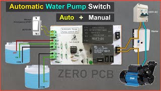
Download the PCB Layout for Automatic ON\OFF water pump switch from the following article
easyelectronicsproject.com/mi...
Required components for the water pump automatic control circuit
1. 555Timer IC (1no)
2. BC547 NPN Transistor (1no)
3. 1k 0.25watt Resistors (R5, R7) (2no)
4. 22k 0.25watt Resistors (R1, R2) (2no)
5. 180k 0.25watt Resistor (R6) (1no)
6. 1M 0.25watt Resistors (R3, R4) (2no)
7. 100nF (104) Capacitor (C4) (1no)
8. 1N4007 Diode (D6) (1no)
9. LED 1.5V (1no)
10. 12V SPDT Relay (1no)
11. Connectors & IC base (4pin)
12. Zero PCB
Here, I have used a 5V pump to show the operation, but you can also use any single-phase pump. Please select the relay as per the voltage and current rating of the pump.
After watching the video, you can easily design this automatic water tank level controller motor driver circuit for your home.
If you face any issue please let me know in the comment section.
#waterpumpautocutswitch #waterpumpautoonoff
------------------------------------------------------
Thanks For Watching...
✅ SUBSCRIBE ✅LIKE ✅SHARE ✅ COMMENTS
Website: easyelectronicsproject.com/
Facebook: / techstudycell
Instagram: / techstudycell
Telegram: t.me/techstudycell/
-------------------------------------------------------
Other useful videos:
LM317 variable DC Power Supply with circuit diagram
• How to make LM317 vari...
How to calculate resistor value for LEDs in a circuit for 9V and 12V
• How to select resistor...  Наука
Наука


Watch [NEW] video on Fully Automatic Pump controller: ruclips.net/video/bgARqosK7T4/видео.html
I learned the difference between TRIG and THR, thanks :)
You have a great quality of helping others, keep it up. Thank you man.
ruclips.net/video/a_Bfu1XWGmI/видео.html
watch last 30 second of my video. i explained state table and state diagram
बहुत सरलता से समझाया आपने, धन्यवाद |
Great video, very clear demonstration, and above all sharing the PCB diagram. Thank you so much.
Glad it was helpful!
@@TechStudyCell I am trying to replace the pump with a solinoid valve. I have just completed the collection of needed items, but unfortunately I got 1.2k resistors instead of the 1k. I wonder if that is okay and if the circuit will work with the solinoid valve. You help in answering my questions will be highly appreciated.
Bro 1 question answer please, isme components me 1k, 22 k, 180k,1m, sub 0.25w compalsary hai kya 1/4 w nhi chalega kya or, 2 question answer please, me isme 6v ka relay use kar raha hu ku problem tho nhi hoga na, resistance ka velue change kar na padega kya , capacitor ka bhi bolo,
@@TechStudyCell it is circuit for motor upto 1hp or not
ruclips.net/video/a_Bfu1XWGmI/видео.html
That pcb is a thing of beauty
The common, pump ON and Pump off wires will get oxidation after some time due to electrolysis process.
Use float magnetic sensor.
Show de bola falou e disse! Belíssimo projeto. Br.
ruclips.net/video/a_Bfu1XWGmI/видео.html
Thank you for your answer. 30Amp Relay se single phase capacitor start monoblock 1Hp 7Amp ki Do (2) motor Ek saath chala sakte hai? Aur circuit ko auto aur manually kar ne ke liye switch kai se lagae?
I'm a hobbyist, and this video attracts me. Now I want to make this project. Where I can get all the components (without the 230v pump) in on one package, can you help?
Your teach very ease,thanks you,
Welcome
ThIs is a great video so far for automatic water control. It is not easy to understand schmatic. Would you kindly explain how automatic water control with 555 timer ic ?
Please, explain the schmatic in detail.
Thank you,
How so creative and neat. Great job my friend! Thank you for sharing.
Thanks so much 😊
Terimakasih telah membuat rangkaian on of water pimp saya akan mencoba membuat untuk tandon air 👍👍👍👍👍👍👍👍👍👍👍👍👍👍👍👍👍👍👍👍
hi and thanks for a lovely easy to follow video im looking at making this can i use these Liquid Level Sensor Controller Plastic Ball Float instead of the 3 wires
A honest and clear demonstration thanks good job best regards
You are welcome
Bro 1 question answer please, isme components me 1k, 22 k, 180k,1m, sub 0.25w compalsary hai kya 1/4 w nhi chalega kya or, 2 question answer please, me isme 6v ka relay use kar raha hu ku problem tho nhi hoga na, resistance ka velue change kar na padega kya , capacitor ka bhi bolo,
Sir please contact Krna ha aap se
Please sir please 🥺
May I suggest, you could put a drain pipe with a height of 35cm above the bottom of the tub. Then you may attach to the drain pipe a N/O mini gas solenoid valve to it & then on of its lead wires is the same attachment to your water pump. So if the water pump is turned on, simultaneously the solenoid valve shuts off not letting water out & as the water pump turned off the solenoid valve opens & releases water onto the reservoir bellow & the cycle repeats as the controller dectects that the water in the tank is low.
I hope it works.👊😁
ruclips.net/video/a_Bfu1XWGmI/видео.html
watch last 30 second of my video. i explained state table and state diagram
The most appreciate thing is your eendless feedback and lovely replies. I subcribed and thumbs up. Proceed. Godbless.
Thank you
www.amazon.in/gp/product/B08QZK2NG8/ref=cx_skuctr_share?smid=A2EY6UBWCE41I5
If you swap the depth of the Red and Green wire in the Tank, you can change the pump to be a bulge pump for boats but put the pump in the tank. Once the water fills the boat and water reaches the green wire which is your safe maximum level of water, then you will trigger the circuit which will keep pumping till the water falls below the red wire and will turn the circuit off. As water fills in again, and reaches tge red, nothing will happen. But when the water reaches the Green wire, you will trigger the circuit and tge pump will run pumping the water out till it drops below the Red and Green wires.
Give it a go.
YOU DID THIS PRACTICALLY, I MEAN IT WILL WORK 100% SAME HAS YOU DISCrIBE
It won't work that way. As soon as the green wire looses contact with water, the pump will start.
We'd need circuit modifications to achieve a bulge pump function.
@@rohanparashar8232 yep thats true, but i can not find the tutorial for bulge pump function. :/
Hats off brother 👏
Thank you for this video
I have a question please
How much the voltage between the cathods placed in the watter ?
Genial, otimo, perfeito, like like like
Thank you, I'm using your design as a basis for my home water well pump on/off control and it works perfectly.
Great to hear!
Can I real use this for ac motor ?
@@kshitijsonar4294 yes, im using this for 200 watt ac pump, so far no trouble. But first please select suitable relay for your pump.
Which relay will be the best for common water pump
@@kshitijsonar4294I'm really not an expert in this, im using cheap 5v relay, as long as it fits the pump rating. But to be safe, you can ask your local electronic store.
Simple and well executed
ruclips.net/video/a_Bfu1XWGmI/видео.html
watch last 30 second of my video. i explained withstate table and state diagram
Fantástico.
Hi dear, I like it today. I ll assemble tomorrow.
Whether it has worked
How much capacity of capacitor you have added in series with positive and ic
Hi, to power thr 5V water pump did you use a 5V AC/DC adaptor connected to the main?
Great! I love this project. Thanks,
Welcome
@@TechStudyCell can I also use this circuit for draining water? If I can i just have to use the normally closed "nc" pin of the relay?
Bro 1 question answer please, isme components me 1k, 22 k, 180k,1m, sub 0.25w compalsary hai kya 1/4 w nhi chalega kya or, 2 question answer please, me isme 6v ka relay use kar raha hu ku problem tho nhi hoga na, resistance ka velue change kar na padega kya , capacitor ka bhi bolo,
Does the position of reference electon in the water matter?
सुन्दर है भाई साहब जी सर्किट
Sir I try super working
great..
Great work brother. But can you help to fix below
Reserve tank sensitivity
Voltage sensitivity
Thank you!
What type of engine do you use in this video to fill the water container?
Can you please explain how it works and for each component
Thanks for your sharing, i wanna try it at home
Please do!
Bro 1 question answer please, isme components me 1k, 22 k, 180k,1m, sub 0.25w compalsary hai kya 1/4 w nhi chalega kya or, 2 question answer please, me isme 6v ka relay use kar raha hu ku problem tho nhi hoga na, resistance ka velue change kar na padega kya , capacitor ka bhi bolo,
thank you man
Welcome
Is it necessary to add led ?
Very good 👍
Thanks
Hi, great video.
Can you make one with solar panels and 12v battery to charge.
Can I use magnetic sensor level and put the two negatives COM together?
Excellence mantor.
Thank you sir
ا
It was great man.thanks too much.
Welcome
First off, great video thank you. Secondly, hiw can i change this so the pump turns off when the water level meets the middle wire and turns on when the water meets the top?
Sir please tell me...this circuit is work in 1 amps
Good job thanks
Is it okay to use a 100uf 16v capasitor instead of 104pf
Tank you very match
Great video!
Superb video And also the background music. Thank You tech study cell.
Welcome
Bro 1 question answer please, isme components me 1k, 22 k, 180k,1m, sub 0.25w compalsary hai kya 1/4 w nhi chalega kya or, 2 question answer please, me isme 6v ka relay use kar raha hu ku problem tho nhi hoga na, resistance ka velue change kar na padega kya , capacitor ka bhi bolo,
Nice idea pr bc547 tranister kay jagy me konsa tranister use karsakta hun?????
Suggest for auto cutoff if manually switched on motors since water scarsity may occur in next year
why this video didn't exist in 2017 !! T_T I could use this as my final project back then..but I just fill the water manually without motor
I like ur plastic and papers pcb idea👍👍👍
Pl cell No
thanks
Thank you very much
You are welcome
Sir on off timer, cyclic timer per video bnayee
On off timer using relay
How to add water pump dry protection when water tank source is empty,help me sir
Excellent circuit
Thanks
Bro 1 question answer please, isme components me 1k, 22 k, 180k,1m, sub 0.25w compalsary hai kya 1/4 w nhi chalega kya or, 2 question answer please, me isme 6v ka relay use kar raha hu ku problem tho nhi hoga na, resistance ka velue change kar na padega kya , capacitor ka bhi bolo,
Good channel
Sir good job, i have question that the supply in for pump is for what purpose if you have already given the supply to the pump?
@wasil Javed please note that only the
neutral is connected to the pump. The phase will be connected after the relay
switches ON ! If you wish , you could employ a Double Pole Solenoid/Relay
instead of the single pole solenoid.
Can it be applied to huge water pumps please
ড্রইং এর মাধ্যমে অনেক সুন্দরভাবে করলেন
Thanks
Could this be made to work to drain water out when it is full. and stop whe the tub is empty
Nice
Very helpful.
Glad it was helpful!
Nice project sir
Thanks
Sir app display par koi water level controller bana sakte hain please?
As you are using DC current in the probe immersed in the water, it will start electrolysis and corrode the probe material ( even S. S.) and the wire connected to it. Use ac voltage for the probe. Needs a better ckt. Good work. Instead of using + ve for common probe, better use ground.
I was looking for this comment... Apparently nobody else said anything about it 🙄 I've changed the wire twice in 1 week 😂 still corrosion is going on
We just need it for a science project for a day, will it corrode?
@@krisp3629 no problem if used for on day.
@@krisp3629 no problem if used for one day.
@@vasantakolkar3397 thank you so much. Another question, will the circuit not work if I use a different capacitor and resistors?
Wow nice good vedio sir...
Brub i got 6th place for this participating in state electronics work experience fair 🎉😊
Disculpe ...de qué amperaje es el circuito?
Thank you for such a nice home remedy "do it your self tech project" .Your presentation is very good.
I want to add one observation to this effort. Generally you will find that water is pumped from ground floor water tank to the overhead water tank. The gadget you have explained will serve good purpose for overhead water tank. However a person need s to ensure that there is sufficient water level in the ground water tank. If that is not ensured the pump may have a dry run for a long time till the ground water tank gets filled with the water. This is a dangerous situation since motor may burn. Plz consider to add another water level sensor for the ground floor water tank. The pump should operate only if there is sufficient water level in the ground tank.
Secondly if the electricity suddenly goes when the pump is running the pump switch must become off automatically inspite of the water level sensors giving signal to start the pump switch. Else when the electricity resumes pump may suddenly become ON again.
Thirdly there should be an isolation switch for this automatic level controller unit, This will be needed when there is leakage of water in the water circuit and needing a repair . This will be leading to hunting of the pump On/OFF condition till repair is done and may not get noticed easily.
Thank you for your detailed feedback. Will do the changes in upcoming projects.
Bro 1 question answer please, isme components me 1k, 22 k, 180k,1m, sub 0.25w compalsary hai kya 1/4 w nhi chalega kya or, 2 question answer please, me isme 6v ka relay use kar raha hu ku problem tho nhi hoga na, resistance ka velue change kar na padega kya , capacitor ka bhi bolo,
apakah dapat di gunakan untuk saklar otomatis pompa air arus ac 220v bro?
Tnx for the video sir
sir First off all Thank you for sharing your great ideas as this simple wonderful project was so useful for us. Actually why cant we make this project little more intresting by making it as an IOT waterlevel controller instead of making this project with 555 timer IC is there any way of using esp8266 and blynk application. If is it possible can you please help us out with that project in the upcomming vedios.
For that u need a microcontroller or Arduino Nano can also work
Thanks 👍👍👍
Welcome 👍
How to use it for 5hp pump, which relay should i use
Can u please share us the design with equations its necessary for doing it as project in collegs
there I have an idea for another project, and so you do it is a controller for a voltage stabilizer system with transformers
Really like the music. Who is that?
This will use only for user Store tank what about main Storage tank and also dry run pump protector we need it
use a nc float switch at under ground water tank ...connected in between power supply to the circuit.
Is it possible for AC supply with the same diagram. If yes, then is there any possibilities for leakage if electric current in the water tank?
a big no
Is it work ok metal tank ??
Very nice design circuit, tried it and it works fine like in your video
The only problem is the common probe (sensor) starts getting corroded over night , if the sensors in some way is AC volts this electrolysis won’t happen, please design
Thanks for the video
hi. does this work with mineral water?
Thanks, very helpfully
You're welcome!
Bro mera circuit chal gya ha lekin band nhi ho rha chala ja rha ha motor me kya jaru
Hello. Nice video and a very good idea.I have a question, it can work to empty the water tank ?when the vessel is full to start the pump, empty it to a certain level and then stop the pump? Thanks.
Just change the order of the probes.
Use stainless steel rods for the sensing probes to prevent oxidation/rust.
This looks like a useful circuit to keep a tank topped off but how about a circuit that pumps water out and shuts off when it reaches a certain level? I would use such a circuit for a 12V 20A bilge pump. I would love to see your version and when I make my bilge system I could link to your tutorial in my own video.
Did you make one?
@@azamchishty6129 not yet. Still working on it
How the wires work in this set up?
Excellent
For this you have to continuesly pass 12 volt current through the water that has to be use for drinking purpose
Good device but I had to add two 1mfd capacitor accross common and start, stop connections to avoid random start and stop due to electric jerk.
Great work around, how about auto on/off switch for exhaust fan after every 30 min circuit with 220V for fan? any suggestions
use nodemcu+relay and flash with sincric pro control or set routine on google assistant on your phone for the way you want for free.
alternatively use 555+relay and set it for half hour astable multivibrator output controllong relay
Why is there a need for 2 power sources and what voltage does each power source need to be?
Can we use this procedure for ac motors?
Thanks
Please which program used for the design??
Thanks
Welcome
can be used on 2 Horse power Water Pump (i.e. 6 to 9 ampere)?
any component need to be replaced else SPDT Relay ? and what Relay can be used to support maxximum of 9 amperes for 30 minutes until the water tank is filled as per the censor wire.
Look to hear for experts.