very nice video this time. without fancy tools no-one can afford other than large companies(with the great respect for the legend Bogatin). This time great presentation with very good clear and concise examples. for almost every main concern od issues you can have on PCB design.
A video on star ground vs. a continuous ground would be awesome. There is some very respectable equipment with star ground, but if a continuous rectangular ground is better, that might help a lot of new designs out.
My 2 cents here is that a star ground has the possibility to mess up your frequency response or stability if you have a design around a few hundreds of MHz. It's all about parasitic inductance.
Thank you wey mutch for this video, I always watch your videos with great interest, because they are very informative and there are a lot of good, smart people. Thank you
I really enjoyed the last "if it ain't broke" part. I have had many clients over the years that strongly believed in the old meaning of the saying. As soon someone tells me this these days I translate this to "we have actually no freaking clue what we are doing". You either want to know all the ins and outs if a circuit, or prevent bad things from happening if you don't know all these things. But just kinda believing and hoping the entire circuit just works is a REALLY bad idea for so many reasons. The biggest one, which was really obvious last couple of years, if what happens when you're forced to change components (in this case I am referring to all the stock shortages).
The "star ground" was used in analog power-amplifiers, where the resistance of the ground track was non-negligible, and the return (ground) current of single-ended loads (speakers) would create mV-level ripple on the ground-reference, which would play havoc on the analog front-end. It is a total non-issue with good differential driving and signaling.
From about 30:47 to 41:10, in a couple of different slides, an ADS8660 ADC is shown with a somewhat surprising input protection network. The "clip positive excursions" diode is shown clipping to the REF input rather than AVDD. I actually went and looked this up on the datasheet, and that's indeed what it shows! I am 50% inclined to think this is an error, as the datasheet section describing the required REF driver doesn't mention absorbing over-voltages. I'm now very curious what the actual truth is on this detail! Arthur hedges his bets by putting TVS diodes on both REF and AVDD (where the latter would be unnecessary if clipping to REF is really how this chip is designed.). Anyhow, thanks once again Robert and Arthur for a hugely informative video! Even when you cover points that we know already, these videos make fantastic references that we can direct colleagues or junior team members to for a particular topic.
Another great video. I do a lot of analog sensing and this is very helpful. And TI does great Ic components in the analog field. What is the osciloscope software around 1:20:00??
Correct me if I am wrong, but at 4:30 wouldn't you want the amplifier as close to the DAC as possible, and the DAC filter as close to the amplifier as possible. That way you minimize the length where lower voltage level signals live and thus can pick up noise, and by placing the filter as close to the amp as possible, maximize the length between DAC and filter (which might pick up noise) which will be filtered?
You are correct. I should update the slides. I would only comment that the DAC output is already a high level signal, so somewhat less susceptible to noise than the low level amplifier input. But ultimately I think you are correct. Best regards, Arthur
Its antiailiasing/reconstruction filters, so in both cases it's no. You are avoiding crosstalk of unwanted spectral content from/to the data converter. "Lower voltage signals" makes no sense here, what you should be thinking about is signal source impedance in first place.
@@Konecny_M It might be an antialiasing filter, but it still restricts the bandwidth over which noise is captured. It might not be its primary purpose, but it still does limit the noise bandwidth. And 'lower voltage signals' is relative to the voltage levels after the amplifier. If you capture any noise before the amplifier it gets amplified by amp resulting in noise levels higher by a factor of the gain of the amplifier on the output signal.
Hello Robert, I watched more your videos it was very intereting and usefuly. I heve a question depend on DRC High-speed rusles. As you know Altium allow define min/max peopagation delay, but only absolute valuse. is it posible use queries (or oyher trick) for check more advanced ? instaed of min/max compare with other value, such as propagation of delay other nets with defined tolerance. Thanks.
Thanks for great video - I try always take notes in my notebook... As for Crosstalk - Arthur show microstrip line... what's about STRIPLINE? It seems distriburion of return current will be other - it's interesting for me watch such pictures like microstrip in this video...
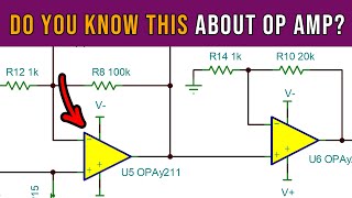
Hello Robert, thank you for the very nice and informatice video, this video raised a question for me (regarding operational amplifer layout), do we need to remove the GND and PWR plane just under the inverting pin and outout pin? or not only we need to reomve GND and PWR plane under the inverting pin and outout pin, but also we need to remove the GND and PWR plane under the feedback track?! if yes, can this make the feedback track noisy? Considering there is no return path under this track? thank you for you help inadvance.


![Seungmin "그렇게, 천천히, 우리(As we are)" | [Stray Kids : SKZ-PLAYER]](http://i.ytimg.com/vi/kAzmhLHePqU/mqdefault.jpg)

Arthur wrote many good articles, glad to have him here!
very nice video this time. without fancy tools no-one can afford other than large companies(with the great respect for the legend Bogatin). This time great presentation with very good clear and concise examples. for almost every main concern od issues you can have on PCB design.
Have not seen more than 10 seconds of this video, but a like is already given. Looking forward to watching this video!
Happy to see Arthur in this channel. His lectures are super insteresting.
A video on star ground vs. a continuous ground would be awesome. There is some very respectable equipment with star ground, but if a continuous rectangular ground is better, that might help a lot of new designs out.
My 2 cents here is that a star ground has the possibility to mess up your frequency response or stability if you have a design around a few hundreds of MHz. It's all about parasitic inductance.
Thank you wey mutch for this video, I always watch your videos with great interest, because they are very informative and there are a lot of good, smart people. Thank you
I really enjoyed the last "if it ain't broke" part. I have had many clients over the years that strongly believed in the old meaning of the saying.
As soon someone tells me this these days I translate this to "we have actually no freaking clue what we are doing".
You either want to know all the ins and outs if a circuit, or prevent bad things from happening if you don't know all these things.
But just kinda believing and hoping the entire circuit just works is a REALLY bad idea for so many reasons.
The biggest one, which was really obvious last couple of years, if what happens when you're forced to change components (in this case I am referring to all the stock shortages).
I'm from Russia. Robert you my you are my best friend, no matter what! We love you very much, all the smart people of America.
The "star ground" was used in analog power-amplifiers, where the resistance of the ground track was non-negligible, and the return (ground) current of single-ended loads (speakers) would create mV-level ripple on the ground-reference, which would play havoc on the analog front-end. It is a total non-issue with good differential driving and signaling.
I agree! Good point. There is always an exception to the rule. Best regards, Arthur
From about 30:47 to 41:10, in a couple of different slides, an ADS8660 ADC is shown with a somewhat surprising input protection network. The "clip positive excursions" diode is shown clipping to the REF input rather than AVDD. I actually went and looked this up on the datasheet, and that's indeed what it shows! I am 50% inclined to think this is an error, as the datasheet section describing the required REF driver doesn't mention absorbing over-voltages.
I'm now very curious what the actual truth is on this detail! Arthur hedges his bets by putting TVS diodes on both REF and AVDD (where the latter would be unnecessary if clipping to REF is really how this chip is designed.).
Anyhow, thanks once again Robert and Arthur for a hugely informative video! Even when you cover points that we know already, these videos make fantastic references that we can direct colleagues or junior team members to for a particular topic.
This tutorial is great, Could you share the PPT with us?
Thanks for next great video!
Thank you!
Another great video. I do a lot of analog sensing and this is very helpful. And TI does great Ic components in the analog field. What is the osciloscope software around 1:20:00??
спасибо, хорошая работа.
Correct me if I am wrong, but at 4:30 wouldn't you want the amplifier as close to the DAC as possible, and the DAC filter as close to the amplifier as possible. That way you minimize the length where lower voltage level signals live and thus can pick up noise, and by placing the filter as close to the amp as possible, maximize the length between DAC and filter (which might pick up noise) which will be filtered?
You are correct. I should update the slides. I would only comment that the DAC output is already a high level signal, so somewhat less susceptible to noise than the low level amplifier input. But ultimately I think you are correct. Best regards, Arthur
Its antiailiasing/reconstruction filters, so in both cases it's no. You are avoiding crosstalk of unwanted spectral content from/to the data converter. "Lower voltage signals" makes no sense here, what you should be thinking about is signal source impedance in first place.
@@Konecny_M It might be an antialiasing filter, but it still restricts the bandwidth over which noise is captured. It might not be its primary purpose, but it still does limit the noise bandwidth. And 'lower voltage signals' is relative to the voltage levels after the amplifier. If you capture any noise before the amplifier it gets amplified by amp resulting in noise levels higher by a factor of the gain of the amplifier on the output signal.
Robert please do some video on magnetics design for smps
may be coming soon ...
@@RobertFeranec and also layout best practices for power supply design
Nice!
Hello Robert, I watched more your videos it was very intereting and usefuly. I heve a question depend on DRC High-speed rusles.
As you know Altium allow define min/max peopagation delay, but only absolute valuse. is it posible use queries (or oyher trick) for check more advanced ? instaed of min/max compare with other value, such as propagation of delay other nets with defined tolerance.
Thanks.
Video on PE earth connection on PCB noise
Thanks for great video - I try always take notes in my notebook... As for Crosstalk - Arthur show microstrip line... what's about STRIPLINE? It seems distriburion of return current will be other - it's interesting for me watch such pictures like microstrip in this video...
sorry - i fixed my question - only now noticed
Hello Robert, thank you for the very nice and informatice video, this video raised a question for me (regarding operational amplifer layout), do we need to remove the GND and PWR plane just under the inverting pin and outout pin? or not only we need to reomve GND and PWR plane under the inverting pin and outout pin, but also we need to remove the GND and PWR plane under the feedback track?! if yes, can this make the feedback track noisy? Considering there is no return path under this track? thank you for you help inadvance.
Nice video, thank you a lot!! What simulation software is used in 50:00
Tina TI