Read a 4-20mA signal with a 0-10VDC PLC Input

HTML-код
- Опубликовано: 13 авг 2019
- In this video we go through how to wire a 4-20mA signal and how controllers read them using load resistors and voltage inputs.
Items used in this video:
Analog Simulator controls.tw/x67bj
PLC Trainer controls.tw/j5ume
Don't forget to like and comment on our videos and subscribe to our channel.
ruclips.net/user/TimWilbo...
Support these videos while you advance your skills courses.twcontrols.com/  Наука
Наука


Excellent, best video I’ve seen explaining this, thankyou
Glad it was helpful!
Great tip, I always thought you had to add an hmi in parallel. Now I know better. Thanks
Glad to help!
Good work Tim.
Many thanks John!
Very informative video. Thumbs up for that.
Much appreciated Aba!
I have been researching for 4-20mA signal. But no luck, then I came to your video, boom all the info i need was there. Thanks again, more power.
Good day,
Why is it needed to convert 4-20 mA to 0 (or 2)-10V ? Is it a practical reason like 0-10V analog
inputs being more common or available on PLC ?
Or any other resons ?
Thanks & regards
Jean-François
Many PLCs have 0-10VDC inputs only. Ultimately, a 4-20mA input is a voltage input with a high precision resistor.
@@TimWilborne I see thanks for this.
Jean-François
You are welcome
Can you please make a video how to configure a 4-20mA in PLC, im using Schneider 334e.
I don't have any Schneider equipment.
Can you do some videos on using the 4-20ma or 0-10vdc simulator on some economizers
The PLC Tools SIM-ALP2 would work as expected on an economizer. I don't have access to one but have helped others figure out how to connect them and test.
Hello. There is a liquid level sensor. Power supply 24V. For setup of the sensor via the power supply the laptop is connected. HART protocol. Can you explain why parallel to an entrance of the laptop resistance of 250 Ohms is included? also in the line there is an analog PLC module. Sensor - Vegaflex 86, Power Supply - Vegastab 690.
Hi Aleksandr. I need to learn more about HART. I'm not sure why you connect a 250 ohm resistor in parallel.
When connect the resistor in series on circuit, is that restrict the overall current flow on the loop?
Yes, there is a limit based off of ohms law. Volts/Amps=Ohms. For 10VDC, 10VDC/0.020Amps=500ohm max. If you have 24VDC then 24VDC/0.020Amps=1200ohm.
Nice Video Tim, Btw I want to ask question about wiring 3 analog 4-20mA sensors. I am using 2 wire transmitter (pt100) and two 4 wire transmitter (flowmeter and PH Meter) to my analog input extension. I did the wiring already where the 4 wire transmitter like usual and I use PLC 24V DC supply for the 2 wire transmitter. The problem is when the flowmeter has no flow at all it has value around (0-30) fluctuates (the digital range 0 - 32000). And i tried to remove the 2 wire transmitter sensor, it reduces to (0-14) fluctuates. Note: I think i have scaled it properly to liter/second for the flowmeter, I have also done shielding + twisting for the flowmeter analog cable, I connected all the ground of every device to the same point. I am not sure how to solve the problem, is it because i use 2 wire and 4 wire transmitter or maybe it could be from noise... Thank You Tim
You need to add a deadband to your flow meter logic. We just recorded a video about this last week but it isn't edited yet. You need to determine the minimum realistic flow that your meter would see. Let's say that turns out to be 100 units. Then in front of your flow meter scaling, put a GEQ instruction with a Source A of your analog value and a Source be of 100. Then add a rung with a LES instruction, source A of your analog value and Source B of 100, and then use a MOV instruction to put a 0 into your scaled analog value.
@@TimWilborne Aaa Icic, i got your point. The fluctuations usually around 0 - 0.01 Liter / second. When i read my flowmeter the min range is 0.977 Liter / second. I think i will use value around 0.1 liter/second as the minimum.
I thought that this small error is caused by the loop from 2 wire transmitter. Thank You Tim , I will wait for that video 👍👍
Hi Tim. Thanks for this and other informative videos. One question; is the 125 Ohm resistor value for a 2 to 10V reading correct. Should it not be 500 Ohm? V= I x R. V = 20mA x 500 Ohm = 10V and 4mA x 500 Ohm = 2V.
Hi Pieter. In this video we used a 250 ohm resistor which equates to 1 to 5 VDC. 500 ohm would get you to 2-10 VDC but this isn't commonly used because it leaves very little room for corrosion and other resistance. 4-20mA transmitters have a maximum impedance which lots of times is as low as 500 ohms so the device can't regulate a current through a resistance that is greater than it's maximum impedance. We talk about it at this link.
www.theautomationstore.com/measuring-a-4-20ma-signal-with-a-voltmeter/
Hi Tim. Thanks for the reply. Do I understand correctly that it is then better to use a 250 Ohm resistor and use the voltage range of 1 to 5V. Is the range between the max and min values not too close. Eg. if I have a 10 000 liter tank with a sensor having 4 to 20mA output, will it be accurate enough to sense and control pumps to add more liquid or for alarms etc.
@@pietervdberg7055 That would depend on the resolution of your analog sensor.
For example, let's say you had a 12 bit 0-10VDC analog input. 12 bit would have 4096 increments over the 0-10VDC range. 4096*4/10=1638 increments over the 1-5VDC range or each increment would be 6.1 liters
If you had 14 bit resolution then each increment would be 3.05 liters. 16 bit would be around 0.75 liters per increment.
@Tim. Hi Tim. Your explanation was very helpful. I looked at equipment catalogues and could see the info on the technical specs. I understand where the 4096 increments for a 12 bit resolution comes from for a 0-10V range (2^12 = 4096) and 4096 x 4 / 10 = 1638 for 1-5V range. Each increment will be 10000/1638 = 6.1 liters. If I follow the same method for a 14 bit (2^14) sensor I get 1.52 liters per increment. This is exactly half of your answer of 3.05 liters. The same with 16 bit (2^16) I get 0.381 liters which is also half of your answer of 0.75 liters. Please explain where I have it wrong.
@@TimWilborne I dudnt find any such discussion at the link provided.
Hi folks. Just tried sending an email with the address on your website, and it says its an invalid email address. Is there a new one?
Hello. Would like to learn more about PLC programming. Thanks
Check out these lessons.
www.theautomationstore.com/lessons/
Thanks for this video,
But I have some inquiries, how much voltage required to operate transmitters? As i know it is 24 DC volt. So as you explain the voltage across the resistor is 5 v,, is this 5 volt used to operate a transmitter?
Not exactly. That was for measuring the voltage across the load resistor which is how the PLC reads a 4-20mA signal.
All 2 wire transmitters have a certain amount of resistance and this is what powers them, this is called "Passive" power. It will be dependent on the particular transmitter and circuit load so it isn't as simple as saying "12VDC" minimum. Usually you will see a voltage range and this take into account the power consumption required for the transmitter. Is there a particular model you are looking at?
Can you make video how to troubleshoot PLC with out of getting into software
We do have videos coming out on troubleshooting analog signals and general wiring troubleshooting but still if you don't know what input or output needs to be diagnosed then it's going to be really tough without connecting to the PLC.
Doug Benson?
Nope, that's not me.
Why analog card reads the signal as a voltage instead of current ?
I'm not following your question. What type of PLC are you using and what values are you seeing?
@@TimWilborne
I mean 4-20 mA signal converted to 1-5 volt in plc, why plc not read (4-20) directly without converting from (4-20 mA) to (1-5 volt)
@@MM-vi9kh All mA measuring devices read a voltage across a load resistor. I think this has to do with precision and cost.
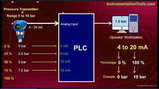
1V = 4mA
A wiring diagram would have been great as it would have given more clarity :(
Here you go:
250ohm
__/\/\/\/\/\__
| |
PLC Input Com
| |
mA+ mA-