
HTML-код
- Опубликовано: 4 июл 2024
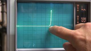
- Sometimes a circuit will specify that the diodes used should be "matched". This can mean a number of things. This video discusses diode matching, how to measure diode characteristics to find devices that match, and some of the good/bad about different measurement methods - from using DMMs to curve tracers.
Notes from this video:
www.qsl.net/w2aew/youtube/Diod...
Video on diode reverse recovery time:
• #201: Basics of Revers...
Video on diode junction capacitance:
• #147: Basics of Varact...
Other simple curve tracer videos:
• #49: Simple Component ...
• #197:Simple V-I curve ...  Наука
Наука


every point you make is very dear to my heart. I'm honored to be one of your students.
Excellent as usual!... +1 for using the scope probe as a pointer... Very precise pointing :P
+1? You sure you don't mean x10?
Great overview and neat to see the Curve Tracer used to compare two diodes. I've never observed that before.
Love the "Back to Basics" videos.
Alan's videos to me are the video equivalent in quality to famous Jim William's app notes. Beautifully explained, well constructed, educational and fun.
Thank you - that's a huge complement! Jim Williams was one of my heroes. Amongst others like Bob Pease, and even Forrest Mimms.
I ran a calibration lab in the mid 80's. The 576 curve tracer brought back many memories.
And now enjoying tubular bells of Mike Oldfield while having a joint :-)
My favorite video series. Thanks again!
Always love your back to basics series
Thank you for making these videos. I learn something new every time I watch. I tend to rewatch them about once a year. I’m trying to repairing an old Tek 5S14N sampler and you component videos are great refreshers on general circuit functionality.
this is a must in many applications. Thank you for spreading the word!
Your notes remind me of the old Forrest Mims books.
Those old Engineers Notebook series of books were my inspiration.
You OLD FART! I thought I was the only one that remembered Forrest Mims!
@@barrybarry6689 I even remember when Big Macs were actually kinda big.
This is unreal. I am going to work on a project first time in years and will start with matching a pile of diodes. The timing of this video :-) Thanks!
I love your videos! You're great at explaining this stuff and I was stoked to see another video posted! Thank you and keep it up!
The characteristics of this video are very well matched with the video content that I prefer to watch. I just couldn’t resist watching the video all the way to the end. I will move on directly to the diode capacitance video now. Thanks yet again for charging up the cells in my brain with a lot of new knowledge. I will try to store all of it as good as I can in my volatile memory for future reference.
/ A long time subscriber
Thank you - I am very happy to know that my videos are helping you and that you find them useful!
Super important and virtually lost concept across all solid state and some tube applications. The old Tek gear is still available both as stand alone and modules for 5000 & 7000 series scopes.
Fantastic video. I'd love to see more particularly on matching bipolars for replacement/repair applications.
Thanks for the great instructional video; this was helpful and informative.
Love this serie back to basics! Thanks
Thanks for another great video! Always learn so much. 👍
Hi Alan, wonderful video as always. Just want to add if anyone is wondering, saturation current also doubles every 6 degrees Celsius. I was trying to work out a way to get that working as a temperature sensor. Which makes it a terrible thermometer over a wide range, but very accurate and fast over a short range, say 1 or 2 Degrees. One could build Cascade levels of sensors to get order level of temperatures then tune with lower order sensors like RTDs, NTCs and finally a diode.
Congratulations, more one great video! I must add it: reverse breakdown voltage must be considered as well.
This guys voice is so soothing to listen to......kinda like the Bob Ross of Electronics.
Thanks for sharing your time and knowledge with the others. Many regards and respects
As always, great video Alan.
Thank you, Alan! Love the series
thanks Alan for Back to Basics, keep posting
The Huntron Tracker I used to use would display a curve of a diode like that and it had a alternating function which would switch back and forth fairly rapidly so you could look at two diodes curves for comparison. With A and B connections.
Always difinitive and absolute awesome! Thank you!
Why haven't I seen this channel before, another hidden wealth of knowledge on youtube!
Be sure to check out the Video Index pdf file that is link on the main channel page (lower right corner of the banner graphic). All videos hyperlinked, arranged numerically and by topic.
@@w2aew Will do thanks
Excellent topic and explanation.
A "more fun" matching task I had to perform was finding two PNP germanium power transistors (TO-3 package), _wired as_ diodes -- in my case, base & emitter shorted together, cases (collectors) as anodes -- for a Harrison/HP 6920B meter calibrator. Those have to be matched up to a current of 5 A, and still have low Vf, as there's only about 2 VAC to play with.
Excellent video. I am _very _*_very_*_ jealous_ of your Tek curve tracer!
Welcome back
Great quality content and fantastic videos. You must have been an apps engineer!
I still AM an apps engineer! (for Tektronix)
Even if I think I know about a given topic, your videos never fail to teach me something.
In a future "Back to Basics", I'd love to hear about the practical implications of Q factor, when you want high Q, when you want low Q, etc. I can calculate it all day, but I'm missing the intuition.
That is not "basic" anymore :-)
These videos are a great. Thanks!
For long-term stability, it might be useful to anneal them for a couple of hours at about 130 Celsius before matching (try and see whether the parameters change...). If I needed to do this often, I would build myself an Arduino shield to vary/measure the current and to record the voltages to plot in Excel. I would attach each diode to its plot. You could categorize them by their Ebers-Moll parameters at best fit and write these parameters on the plot as well. It is likely that average parameters occur often so that you could put these easier-to-match diodes in a separate file folder.
Great video Alan, thanks
Great video as always.... I didn't know that common diodes could swing that much due to manufacturing and temperature variables. 73's KC2RDU
You should add "CURVE TRACER" (CT) and "TEKTRONIX 576" to this video's TAGS so it pops up in searchs. I love that TEK 576. It's appearance in this video was a great summary of CT usage.
well,I am a 67 year old carpenter and shade tree mechanic.. But time has taken a toll on my body so I can not longer do the things I once was..Because of that I have decided to teach myself electronics (stop laughing! Well.. ok you can chuckle a bit.. I mean it is rather funny)BUT! you have taught me a lot in the short time I have watched your videos. and I want to say thanks.. you male it simple enough for an old fart like me to "get it".. I appreciate that.. carry on..
Great video, thanks.
Great info!
Nice review Alan, thanks for sharing! 73 - Dino KL0S
Great video! Thank you!
Thanks for posting nice video as always
Just a thought for the backlog, might be interesting to characterize and/or differentiate some of the HDTV antennas that are on the market.
Thanks Alan!
Thanks for the upload. Isn't this another application well suited for a LM10? At least if someone wanted to go a step further than resistors on a breadboard, prototype a simple one-off adjustable tool, but without the curve tracer or adjustable bench PSU setup. I think you're the one that introduced me to the LM10 too :-)
Thanks again.
-Jake
Yeah - I love the LM10!
Nice! Thank you for sharing.
Nice work, I hope next one is matching JFETs? ;)
Good luck. JFETs are a mess when it comes to parameters.
Superb!
Another excellent and to the point video Alan! Keep em coming. 73 KE4EST
Im starting to believe Allan can see electrons : )
Allan most of my explorimenting involves solid state devices although I am very interested in vacuum tube tech and have built a few tube circuits without full comprehension in particular grid leak could you please please do a video on Grid leak (what it is, how to properly select correct grid leak resistors, how to correctly make necessary associated measurements pit falls and caveats etc thanks S
Thank you
As a side note, using a DMM to measure the diodes used in sensitive RF detectors can catastrophically damage them (the junction size is tiny to minimise parasitic capacitance). I've heard of technicians "buzzing out" a batch of RF diodes destroying each one as they went about their work!
Amazing video!.... Can you make a video about AC vs DC biasing in old cassette recorders. Thank you
Interesting topic - haven't thought about that in years. I'll have to see if I have any old tape machines where I can do some experiments on bias type/level vs. fidelity and distortion. Here's a quick basic reference wiki page: en.wikipedia.org/wiki/Tape_bias
good video
Great 👍🏻 tysm
You could also use the current limit adjust of a PSU to set the current to a test level say 500mA (1N4001 Diode), stick the diode (Anode to +V) across the terminals and then ramp the voltage up past the point the PSU current limits then measure the voltage across the diode.
If you leave the PSU Voltage set high then simply varying the Current limit up and down while measuring the Diode voltage will give you a poor mans curve tracer (Manually plotting the readings on graph paper yourself).
Thanks for the Vid Alan, don't see you a lot now a days....
I've used the current limit on the power supply like this, mainly for checking LEDs. On some of my older analog supplies, it is difficult to set a low value current limit. One caution about this method - the current limit function is usually on the regulator circuit, before the output filter caps. So, if you let the supply run without a load, the voltage will rise to the setpoint, with the output caps charged to this level. If you then connect a device like an LED, the caps will discharge (with a high peak current) until the voltage drops low enough to to hit the current limit.
And yes, spare time for making videos has been hard to find these past few months...
you can make a constant current source with a precision zener reference and also an op amp so that you know the current and you can pump this known constant current and read back the voltage , Force Current Measure Voltage !!!
Hi and will start by thanking you for all the great videos ! I was hoping if you could tell me if you have ever covered verifying that earlier stages/transistors are OK when you have failed output transistors. If not would it be possible for you to cover this subject use bare bones equipment (like me ) and what to look out for as to save yourself another run to the electronics shop .Thanks again
Ron (Fremantle downunder)
If the equipment can be safely turned on, the best place to start is always to check the DC operating voltages (power supplies, and bias voltages around the transistors). Failed transistors will often be obvious due to bias voltages that don't make sense with respect to proper transistor operation.
As usual, a great video. I've learned so much from you. Can the same technique work for transistors?
For measuring Vbe of bipolar transistors - yes. But, keep in mind that matching transistors can be much more involved than matching diodes, because they may need to be matched in Beta or other parameters as well.
@@w2aew Thanks Alan .. 73
A curve tracer will be suitable for that. Not so diffcult to build with all schemas on internet. or if you have an Oscilloscope and a modern generator with stair case wave form. I thing Allen has a video that shows how do construct a curve tracer.
As a side note, using a DMM to measure the diodes used in sensitive RF detectors can catastrophically damage them. I've heard of technicians "buzzing out" a batch of RF diodes destroying each one as they went about their work!
Great video. When matching transistors for a LTP, do you mainly go of Vbe matching or hFE matching? Or both?
I’d probably start with Vbe to minimize offset.
Hi Alan, I was wondering if you can perhaps do a video on resolving second harmonic interference within high frequency switching circuits that are used in RF applications. TOI is often mentioned within the engineering community, but when it comes to the second harmonic not much can be found. So I was wondering if you can do a video about SHI and on points on how to resolve that said interference.
I can add that to my long list.
When matching transistors you mostly match the HFE, but when using a curve tracer or DCA pro you can match transistors by their "early voltage". I'm not sure why would you want to match transistors by their "early voltage"? If the transistors Match the collector output current, base current and HFE but "Don't Match" the early voltage, what will happen?
A dual channel SMU does the same and you can collect the data too as csv and compare in excel
So very interesting, Thank You! Can the "Q" of AM radio reception be affected by the quality of a diode? (How) Can the AC/DC load on a diode be measured? Thanks!
You can certainly measure the voltage across a diode with a meter or scope.
Hi Allan can we do away with the resistor and use the current limit of power supply to set the desired current across DUT excellent video as always thank you.....
Yes, but only if you ramp up the supply voltage after connecting the diode. If you let it float to the setpoint and then connect the diode, you can get destructive current as the output caps on the supply are discharged through the diode until the voltage is low enough for the current limit to take over.
@@w2aew ha thanks i have had the pleasure of that experience testing zener voltage in this manner ''wait they cant all be dead out of the bag'' ''oohhhh'' doe lol i would like to set up some way of characterising can i set up my sig gen to produce a ramp either directly across the DUT or onto the base of a transistor..?? would this work ? Thanks for your time it means alot
was thinking of using both channels of sig gen.. First identify a diode with the characteristics you want to match place it in say ch1 apply a ramp then swap out ch2 with diodes while applying the same ramp to it at the same time comparing the result directly on the two channels of my scope?
@@w2aew this was really surprising as I built the power supply myself and deliberately kept the output cap very small as to not destroy things when I connect up my circuits and there is some thing wrong (most times) lol
@@T2D.SteveArcs That'll work (using a two channel FG)
hi w2aew, Do you have a video on the best way to impedence match. Thanks
I have a few videos on designing impedance matching circuits - see my series on the Smith Chart.
Can Lab Bench DMM meters change the "current settings" when measuring the resistance ohms? These is often tests done for measure the diodes leakage which would increase the current and measuring the diodes resistance it will change depending on how much current you're applying to it.
If you manually change the range on a bench DMM when reading resistance, you will generally change the applied current.
ok thanks i didn't know they use match diodes in log and anti log circuits, I rarely have seen op amp based log and anti log circuits not often used in schematics i have seen and I'm not sure where they use log and anti log circuits in besides in electronic theory text books i have seen them. They say i was testing leakage current in diodes was measuring the resistance of the diode, if the diode has low resistance i just thought it would cause leakage current because the low resistance means the diodes junction resistance is low resistance and is passing leakage current.
Same always ❤️ super 👌💯 perfect
You mentioned a source measure unit as alternative to using a curve tracer.
Yes, a SMU (source-measure unit) can source/sweep a current or voltage and simultaneously measure voltage or current. Newer ones feature graphical displays and can plot results.
Yes i have notice when changing the resistance range its changes the applied current. Your Curve Tracers showed two different signatures from the same diode batch lot. It looks like one diode turn ON soon at 500mV and the other diode turned ON at 400mV. Any reasons why the diode turn ON or start conducting at different points? I'm not sure what this electronic term is called when the diode turns ON threshold point. I have measured the diodes resistance ohms and they measure differently and not sure if this is leakage testing a diode or what other ways to test diode leakage using a curve tracer or DMM. What application and circuits would you want to "match" the diodes? you mentioned it but didn't explain more about it.
Fabrication variation, packaging stresses and other things can cause changes in diode turn-on characteristics. Using a resistance measurement is just ok for doing a quick go/no-go testing, but the resistance value is meaningless. Leakage is measured under reverse bias conditions. Matched diodes are used in a number of different circuits, such as balanced modulators, mixers, etc.
any other circuits besides balanced modulators and mixers. I have seen matched diodes for wheatstone bridges and bridge rectifier, balanced modulators and mixers in RF circuits, but what other circuits use match diodes? How can you test a diodes leakages without using a curve tracer because a DMM meter you can't test a diodes leakage. I have just used the DMM ohms resistance to test the diodes leakage, but i know like you said its not a good way of testing leakage. So what is the correct way of testing diode leakage test?
One application that requires matched devices are circuits that perform log and anti-log responses, etc. You can test leakage with a power supply and ammeter. Apply a reverse bias voltage and measure the current.
Would either of your curve tracer examples (#49 o #197) be sufficiently accurate to use to match diodes? Thanks for your great tutorials!
73s - VK7FPCL
Yes, either of them would work pretty well for matching diode IV curves - best if you wired up a DPDT switch to quickly switch between a pair of devices for comparison.
@@w2aew Don't know if it can be done but the thought occurred to me to use the storage function on my scope to capture the image of one test and then superimpose it over the other. ;-)
For matching 2 diodes(or transistors)the curve tracer to my opinion should not even have to be calibrated. What's important is that the curves are same.
@@w2aew I wonder why Tek have chosen to omit an electronic (variable freq.?) switch while designing those (expensive us$2,125 in 1969) machines. Did not they have to match devices at that time?
@@yoramstein Yes, that's right.
A slight problem with diodes and temperature is that the diodes are not on the same die and probably several mm apart. So if parts of the PCB have different temperatures, because let's say you have a fan cooling and/or some transistors heating up. Then your perfectly matched diodes will still diverge.
Heat shrink two diodes together with a drop of thermal paste or thermally conductive glue to enhance thermal coupling.
And to take it one step farther, include a 1/2W resistor and run it at a current that raises the diodes about 20 degrees C above ambient. (Ambient in the area they are located, not necessarily room temperature!) This will pretty much isolate them from temperature changes in the equipment.
@@lwilton Hmmm, the problem I'm talking about is that there will be a temperature gradient, I'm not sure how one 1/2W resistor will solve it, if anything you want to place 1/2W resistor between every diode. Then you'll get a reasonable equal temperature among all diodes.
Or you just place them in one place and pour generously some thick thermally conductive glue onto them.
@@NiHaoMike64 That makes a lot of sense, another thing you can do is to have a thick ground poor near the diodes
I was trying to describe a cordwood construction where you put your 2/3/4 diodes in a hunk of thick shrink tube with a resistor in the center, touching all of them equally. Put a couple layers of shrink tube, or a wrap of cork below the shrink tube if you want better thermal insulation.
That was a traditional cheap "thermal oven" that was commonly used for (semi) temperature stabilization of small matched parts in things in the old days. You typically used a regulated supply to the resistor, but didn't attempt temperature control; just ran it enough above ambient to keep it moderately constant.
I tried this on discrete diodes and it works well. When I tried to compare quad pack diodes TI UC3611N
the voltage seems to wobble vary a lot. I used my power supply directly in CC (current control) mode.
It work well on discrete 1N5818 diodes but was not stable at all on the IC quad diode packs with the voltages
varying much more diode to diode for the same current ? Any ideas what might be causing this ?
Strange - not sure what could be causing that. Maybe stray pickup from the other diodes? Try shorting all of the unused leads together when testing one of the diodes. Maybe even grounding the unused pins...
Seems most diode and transistor measurements these days use (SMU (Keithley 236 for example) with a external shielded rig of some sort as full on Keithley parameter testers can cost $10k second hand for a basic model without all the external fittings.
There is another alternative to Keithley's, often much cheaper one: HP/Agilent 4142B. With some patience can be acquired
Hi, What would be some examples of RF/Ham related applications for matched diodes?
Usually you'll find matched diodes in things like a double-balanced diode-ring mixer/modulator.
@@w2aew What characteristics would a circuit or device exhibit that have poorly matched diodes where matched diodes are called for?
@@howardroark3052 It depends highly on the circuit and application. In the case of a diode ring mixer/modulator - mismatched diodes will cause distortion, which will result in poor balance (cancellation of fundamental and LO signals), as well as increased intermodulation distortion frequency components.
@@w2aew Thank you for your thoughtful response! As a beginner electronic hobbyist I find it fascinating to learn about the advanced aspects of it. Your videos are exceptional!
@@w2aew can you tell me what sort of current (current range) I should be using when testing/matching diodes for a balanced modulator? I've got a heap of 1n4148's - I assume they are okay for 3.5-14mhz.
Isn’t there a certain expected resistance measurement you would expect to test them too?
A resistance measurement is not a reliable way to match diodes, since they're not pure resistors.
guys why my videos does not appear on search please someone help me
I might have missed it in the video but it would be good to mention that accurately matching diodes has a temperature component as well.
You'll have to watch to the end - I talk about temperature effects near the end of the video.
@@w2aew ah I missed it. I had to stop with 5 minutes left to go. Ignore my comment then.
Ohm my gosh you should try this application! hunt for circuit solver on the playstore!
Those curve tracers are pretty cool, but hard to find (and expensive!) now and most basic scopes today don't have an XY mode, which kind of sucks since it limits what you can do.
Yes, I know. Check out my videos #49 and #197 for simple curve-tracer ideas (both require XY mode though).
These days A/D and D/A converters are cheap and easy to come by on things like a small and cheap Arduino, though usually limited to 3.3V or 5V. But you can easily hack this up with some resistors to measure a higher voltage, and use an opamp and a pass transistor to set a current to measure with. Then you can make yourself simple digital curve tracer, and even record the curves of each diode you measure. I did that a few years ago using some old PLC hardware I had lying around.
@@lwilton You certainly can rig something up. I used to use old automotive ECMs for some cheap datalogging since they were easily hackable, had serial comms and lots of A/Ds, counters, drivers, etc. already built in. But its still nice to have a legit piece of equipment on the bench.
@@mysock351C We had one were I worked and it came with its own trolley. VERY HEAVY.
@Dick Fageroni I have a variety of them since I have a few GM cars. These where used in various models of Chevy/Pontiac/Buick/Saturn, etc cars through the years. The earlier Delco ECMs are the GM TBI and early batch fire C3 ECMs used from roughly 87-92 in a variety of GM vehicles using split PROM/ROMs. Basically there was a PROM for the vehicle cal, and a ROM with a primitive operating system. Theyre limited in what they can do, but very easy to program since they are the old Moto 6800 processors once you consolidate the PROM and onboard ROM. The later 93-95 ones where 68HC11's using EEPROMs, and currently I have a 98-01 M68332/CPU32 GM PCM used in pickups and light box trucks in my Camaro since it supports a distributor and has OBD-II flash capability and can run executable code over the OBD port. To use them I downloaded the raw binaries and generated my own source code to customize them. Theres still a bunch of commented sources and apps to program the 87-95 TBI and 98-03 VPW PCMs that I wrote kicking around on the 'net somewhere, and others have done a lot of work as well so they're well documented. I have some of the later CAN bus/PowerPC based GM/Delphi PCMs, but I haven't had much time to work with them as of late.
I enjoyed the video! KC8JLW
Be careful when you measure with really precise multimeters and you touch the diode on both ends with moist fingers you can make a different in the measurement.
True - but in the case of measuring diodes, the several hundred kohm resistance of your fingertips won't have much of a affect on diode measurements. However, holding the diode in your fingers can raise the temperature of the diode, that THAT will change the reading.
what's with those dislikes?
Great as always dear... very informative