FM Crystal Detector Live Recordings

HTML-код
- Опубликовано: 5 сен 2024
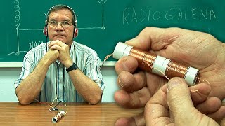
- Live demonstration of an unique FM crystal detector with non resonant magnetic field loop. Lowest number of parts. All parameters are described. Transmitter in 3 km distance. Receiving broadcast signals up to 13 km possible.


It's so cool! I'll try to make for FM! Thanks for sharing! I've made this one too, but for HF only! It works!!!🌞🌍👍
That's interesting I made a 40 m HF
@@ronalddaub7965 nice
This kind of detector works on a 'slope tuned' principle to receive FM.
That's correct
Howdy.
Wonderful example of thinking outside the box. The box being the assumption that vhf amplification should be mandatory for detection. The diode should be a vhf germanium diode for example AA144 or 1N34.
One may try biasing the diode by using a 1,5 V dry cell and a very large esistor, say 22 M in series with the diode. The current will be negilible but it will keep the depletion zone in the diode active.
Regards.
Top Performance passiv FM UKW Detektor...👍😸😸😸best Regards AM Coilwinder Matthias.
Крутой приёмник 👍👍
I make it with BAT32 diode but just catch several FM signal with crude and very low signal.
But when I replace the Diode with 1N5819 (salvaged from old phone charger) which voltage drop just about 0.2V I was successful catch many FM signal with good reception!
It's work not because the Diode is germanium or silicone, it's just about Voltage drop.
I make it, and work very well 😃😃😃😃👍
Nice to hear that you have success with this circuit. The drop of about 0.2 V and very low capacitance is the advantage of the BAT shottky diode. Try also the BAT 15. Germanium diodes have some higher drop voltages, but can give also good results here.
@excuse me Whattt both of the diodes have frequency maximal of 1MHz typical, so I doubt its work... For simple use just look for your phone charger that not use, the diode on the output always Schottky and worth to try,
@@samuelbudiyanto2250 Hi, I have been lookin for diodes and funded the new 1n60 wich is schotky barier an has a recovery time of 1 ns. Will it be 1000 mhz? Thanks to share!
@@samuelbudiyanto2250 The diode is to detect the audio signal (which is normally between 20 Hz and 20 KHz), so this should be fine. It doesn't have to be in the FM range.
That is super cool
For better reception you can connect this tuned LC to 75 Ohm dipole antenna or 300 Ohm folded dipole (2.14dBi) or Super-J-Pole collinear 4.8dBi antenna.
Of course you can do so. But the coupling must be very low to keep the bandwidth small. Resonance Z is about 70 kOhm! To enhance the result an unconnected open 3 meter loop near the mini loop is practicable.
@@JpChannelOne when you say here unconnected open loop what do you mean exactly?
@@EnriqueVetere that mean lambda loop in the near.
Coole Schaltung👍
Very cool.I was able to pick some hidden frequencies in russia. it was like airplane radio!V
ery simple and easy!I love it!
Amazing!
For FM radio a rod of 77.5cm is more appropriate, but dipole antenna has higher efficiency.
But the circuit diagram is AM, not FM ???
Yes, the circuit is like for AM. However, the FM signal is before converted into an AM signal at a slope of the resonance curve, which is then not tuned to the maximum.
I love it good
Спасибо 👍👍
Now I gotta learn how to read schematics
It works in Bulgaria.
Very nice project, thanks for sharing. I wonder how critical is the copper wire section for the loop (4mm), can it be say 2mm or 5mm? can it be hollow?
You could also use silvered wire, of course. For 1.5 mm please find examples here:
ruclips.net/video/QDlCOB80kVE/видео.html
Hollowed copper is also possible. Important is the Q of the tuned loop, the overall-bandwidth should be below 150 to 200 kHz. Usefull is a loop calculation program.
@@JpChannelOne Thanks a lot. Would you have a link to such a program/calculator? or any link describing some theory of operation, I don't get how tuning happens, for example.
@@EnriqueVetere I used this calculator: www.dl0hst.de/magnetlooprechner.htm
The tuning happens with the variable air condensor.
I’d like to build this can you use pizzeo electric headphones instead of an amplifier?
Basically yes. However, this depends on the field strength of the surrounding stations. Bypass the crystal headphones with approx. 200 kOhm
use 1/4 wavelength wire antenna connected to the side of the diode for max signal.
Cool man :)
Slope detection? I see no Foster-Seeley nor ratio detector, just an envelope detector.
Yes, concerning FM it is slope detection. This is the simplest form of a FM demodulator. It is a tuned-circuit frequency demodulator type wherein it converts FM signals to AM using the slope curve of a tuned (LC) circuit and extracts the audio information from the AM envelope with a fast diode followed by a proper RC combination. For AM demodulation the same circuit could be used at the tuned maximum and then it would be indeed a well known envelope detector. Important for a succesful FM broadcast receiving is the resulting bandwith of the LC circuit below about 300 kHz, the near of the transmitter stations, a fast diode with very low self capacitance, high impedance ear phones or an amp with more than 50 k input-resistance.
Are you interested in Raudive diodes ?
@@charlesloukas5909 For EVP? I am, but ASAIK they just pick up random RF and the brain makes up the voices with pareidolia.
@@janetwinslow2039 machine hearing should be used in researching EVP
FM receiver without batteries and 1920,s style...
have you tried on high-resistance headphones?
Yes. But signal is very low. The common magnetic 2k, 4k phones are not sensitive enough and their impedance is too low. So you need a crystal earphone or sound powered headphones.
It could be mistaken as magic!
Where'd you buy the BAT 32 diode at
Recommend Mouser, Infinion. Also BAT 15 is possible. Look at lowest capacitance and highest differential resistance.
VOU MONTAR. PUBLIQUE OUTROS PROJETOS
Whar kind diode used?
Shottky, low capacitance < 0.5 pF
i am a beginner . how do i learn theory thank yuou
I recommand articles on fm slop detectors.
@@JpChannelOne thank you
FM ???
Yes !!!
This makes no sense.
Why?
@@JpChannelOne I built a two transistor FM receiver that looks like it won't work, but it makes the transistors into a tunnel diode. There is no "FM" detector in your circuit either, but some people have never seen "Slope Tuning" that can pick up FM by tuning beside the center frequency, so you get audio, but you can get static also.
@@mrdovie47 First FM receivers used also slope detection as done here. The condition is furthermore a bandwith smaller than about 300 kHz. The loop diameter is choosen small to fullfill that, but big enough to get sufficient signal. The next condition is a diode with low capacitance and forward violtage which is why I use the special shottky. Try it out, that is functionable.
@@MauriatOttolink ruclips.net/video/bZlIx4CGtX4/видео.html Is an example of the two transistor "FM Receiver" I've seen. The circuit looks strange with bases and collectors shorted, but it makes a "poor-man's tunnel diode" You may have to try several transistors to get them to go into negative resistance. I have played around with this at way lower frequencies. The 22K resistor should be a variable pot (50K or so) since the bias is critical to get into "tunnel diode" mode.
I once built a multiplex stereo adapter kit for an old tube radio I had as a kid and got it working, some of the best sounding FM I can remember came from it (1960's).