I have a 2 year associates degree in this trade. I have read numerous HVAC books I have yet to see a better explanation of boiler wiring than this video. Job well done 🎉
This is a great example for someone in the field for at least 2 years doing service. To many words for a common person to understand. I was taught this way in 5 min, back in 1984 by a drunk serviceman who didn’t want to go to the service call. And I had to go, Think of the zone valve wiring like this , close your eyes and picture 2 wires from the transformer wired directly to the zone valve motor, load from trans to 1 yellow wire and common to 1 yellow wire. Now picture breaking 1 wire through the thermostat, one side to the R and 1 side to the W of the thermostat, it really doesn’t matter which wire you pass through the thermostat is just a switch to feed the zone valve motor. And the 2 red wires feed parallel to the T T circuit of the circulator relay. Stay consistent for each additional zone.
I like seeing new guys getting into the field. And learning the right way. Some tech’s think new guys are stealing their jobs. I always teach new guys and think of it as they will be paying my pension 1 day. Eric
Mike is the BEST HVAC instructor on the planet! He gets right down to business in his videos, using simple, clear, hand-drawn diagrams and language (taking care to define all terms). He organizes his videos by first stating the overall purpose of a system and then developing the components and their connections in bite-sized pieces (that I can absorb). Mike also provides the fundamental HVAC and/or electrical theory that underlies the design of the systems that he is explaining, i.e. he provides the WHY that supports the WHAT of the systems. This makes the material stick. Thank you so much Mike! Jimmy from Massachusetts.
Just installed a new (replacement) 4 zone boiler in our workshop, and then tried to follow the old wiring pattern without knowing what did what. I could not get the thermostats to control the call for heat and so started looking for info on the internet. |Nothing really helped me until I came across your video. I had to watch it twice and I printed out all 4 of your diagrams and made notes on them. Once I understood how it all worked, it took less than an hour to straighten the wiring out and voila, it all worked as it should. I am confident now that I could wire up any boiler to work multiple zones. Thank you!!!!!!
Thanks . I watched few videos to how you wire a Honeywell zone valve 4 wires and you the only one explained in easy way to understand without confusing. Thanks again keep up the good work.
This video is so clear and helpful! It gave me the confidence to use an unused wires as a C wire for some new thermostats without accidentally shorting anything!
I’ve always struggled with zone valve wiring. You’re videos have really helped me understand the wiring and how they work. I am a lot more comfortable now going on service calls with zone valves. Thanks for taking the time to do these videos!
The working model really brings the explanation to life and makes it all really clear. Thank you SO MUCH for taking the time to put that all together. Looking forward to seeing the explanation of how the other zones are wired in.
I don't have enough words to say thankyou, but now make sense to me explaining precise and concise how connect life savers thanks God bless you keep the good work.
Thanks this was great! I'm a homeowner doing some investigation on how to hook up a C-wire for a smart thermostat, and this helped understand all the wiring so much!
Great explanation. As a do-it-yourselfer found this really easy to follow. You mentioned that a second transformer might be necessary for systems with 5, 6 or more zone valves. I assume that holds true for any combination of zone valves and thermostats which require a constant 24V to keep them connected to an internet router for WIFI capability. The reason I say that is I have a 3-zone hydronic system connected to 3 smart thermostats requiring a "C" wire. Two of the thermostats control both heat and central air with the third controlling just heat. The transformer at the boiler has a "C" terminal and there's a spare wire at each of the thermostats. If I connect the spares to the Common terminal at the boiler, I get less than 24V. It's a sufficient enough drop that the thermostats will not stay connected to my WIFI. Someone recommended using a second transformer strictly to provide the constant 24V. My question is if a second transformer is used and I connect the Common terminal to the spare wire at each of the thermostats, where does the second wire go? Any possibility of you doing a video on this topic but with smart thermostats requiring a "C" wire.
I was sitting here thinking about what my next video topic should be and I think this would be a good one, so I will make it this weekend. Just on a side note, most smart thermostats operating independent heating and cooling systems prefer to draw the common from the AC system, so hooking the common to the boiler may have crossed some circuits and is likely why you had experienced a voltage drop. Adding a second transformer is a little more complicated than just 2 wires. A little rewiring is necessary, and a relay has to be added to keep multiple control circuits isolated from one another. I'll cover it in the video.
I need simple "HVAC for Dummies" as I am an electrical engineer, not an HVAC expert or an electrician so it takes me longer to get it! The Jersey Mike series is freaking brilliant as he shows both transformers and complete loops so I finally now understand what the other non Jersey Mike videos were saying. Thank you Sir! I am anal-retentive and want to label all wiring and diagram my system and now I can do that. I sincerely appreciate this man's efforts. Thanks Mike!
Well, I should have watched this video before the install a nest power adapter video. That was very helpful at explaining the overall system. Thank you. I would reference this video as a first step for people new to hydronic systems in your other videos!! Very well done. Thank you.
I like seeing new guys getting into the field. And learning the right way. Some tech’s think new guys are stealing their jobs. I always teach new guys and think of it like this , they will be paying my pension one day. Eric
Get this man a beer. I had to remove a zone valve and the wiring got quickly messy. Ended up needing to keep the remaning valve open and I guess I just had the thermostat directly hooked to the furnace. I didn't understand the second set of 24v wires comming from another transformer outside of the furnace and where to hook them up.
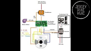
FOLLOW-UP: it turns out... this isn't the only way to wire the zone valves. i'm no expert, but this is how my brilliant HVAC guy explained it to me... when my system was installed, the original HVAC guys used a second 24V transformer at the air handler. So, I have two 24V transforms, one in the air handler and one at the boiler - very misleading... 3 HVAC guys missed it. 4th guy was a genius. The 24V at the boiler is only for the indirect water tank. Since the air handler already has 24V, you simply connect the red from the thermostat to one of the yellow wires on the zone valve and connect the white from the thermostat to the other yellow. ORIGINAL POST: great video! My Honeywell seems to work fine: turns the motor when heat is called, triggers the pump and closes when the cycle is complete. However, the cover was off and i almost burned myself on the motor head. I put a meat thermometer to it and it was 190°. The water temp gets to 180°. Is this normal? Does the heat from the water really transfer to the motor head plus some heat from the electricity to keep the motor on? or do i have a short? big thx
@@atlasfueloilinc.2421 thx, but no. the thermometer was the key. the zone valve rose ABOVE the temp of the water - which is impossible with simple thermal heat transfer. there was no fuse to blow. the last hvac guy corrected that, as well.
Thank you for the explaination! Here is my situation. My apartment building zone valves had water hammer. So what they did was they disconnected the 24vac to the zone valves and manually opened up all of them. They have one central location where they controll the heat. My apartment gets too hot so I added a 24vac transformer to my zone valve so I can turn off my heat. Back to water hammer. How can I slowly close the zone valve to stop the water hammer? Can I use a 16vac transformer? How would I slowly decrease the voltage to get the zone valve to close slowly? (I don't want to mess with the spring) thank you!
Typically after the zone valve on the way back to the transformer's "common", but it depends on the number of stats and zone valves are on the transformer. Sometimes an extra transformer and relays are required to feed all of it without issues or the loss of smart features.
Thanks for the great explanations, Mike. However, on 9:47 minutes, the diagram shows that the red wires connect to a switch inside the Zone Valves that bridges Terminals T and T od a transformer Those cannot possibly the the terminals of a transformer, as it would short out 24VAC. There must be some circuitry inside that is between the 24VAC transformer and the switch. Other than that, your video is perfect
The t and t don't wire directly into a transformer, but through a larger burner circuit and control board that in turn is powered by a transformer, so yes there is other circuitry involved.
This was great Mike, any suggestions on how to organize and keep the wiring for 6 zone valves and 6 thermostats neat and tidy? And just like you explained I have 2 transformers to distribute the load over the 6 zone valves. I was wondering if there might be a panel of some sort that is prelabeled for connecting the wires ,kind of like making it idiot proof but also keeping it neat.
I have8 zones, but now I see how they are linked together, Now I got to get it simpler. And you aren't wrong about that multiple calling situation, mine was wired with just 1 transformer.
I trying to wire in properly, a Erie Poptop actuator 4 wire. There wire diagram shows 24v, load to R, thermostat, W to black wire actuator, other black to common. What are your thoughts on this? First zone seems to be working properly. Now time to wire in second zone. Thanks much
Mike your awesome man! I learned alot in the few vids I've seen. I'm in an area where hydronic isn't used so no plumbers will touch it. So I've been doing research and learning as I go before I get it all started. Could you do a video on my system so i know if I'm headed in the right direction! Jk I'd gladly pay you for your time if you'd be willing. Thank you, firefighter here building my own house I know a little of everything but very little of the whole. Jack of all trades kinda guy
@@JerseyMikeHVAC Yes sir it is a boiler that'll handle potable water as well as heat which a plumber will install... im no plumber by any means. But I hopefully can get it going with the heating side.
Hi, I have a question for you on the C wire topic, but first let me say thanks for this incredibly helpful video. The diagram is excellent! Before I get to my question here’s my situation. I have multiple Honeywell zone valves connected to thermostats and transformers in exactly the way you depict in the diagram, except for one difference. On my system, the white (common) wire coming from the transformer is pigtailed and connected to the yellow wires leads from the zone valves. Then the other yellow lead is connected to the white wire going to the thermostats. At the thermostat, the wiring is consistent with your diagram. The red wire is connected to the RC terminal and the white wire is connected to the W1 terminal. The red thermostat wires are then pigtailed together back down in the boiler room with the red wire going back to the load terminal on the transformer. So basically everything is the same as your diagram, except at the zone valves the white (common) wires are connected to the yellow leads instead of the red (load) wires. So now to my question. I currently have WiFi thermostats that run on batteries and are constantly running out of power. I’d like to add a C wire to the thermostats. The cable that runs from the boiler room to the thermostats is 18/3 wire so there’s one extra unused wire. My understanding from your comment is that I can connect that third unused wire directly to the common terminal on the transformer and the other end to the C wire connection on the thermostat. I will pigtail the commons at the transformer so I can do this for multiple thermostats. First question-is this the correct way to wire the C wire? Second question-with my opposite use of the load/common wires at the zone valve, will this C wire configuration work? If it’s helpful, my zone valves are Honeywell model V8043E1061, which are normally closed. Thank you!
Your wiring is essentially the same circuit I used in my video only in reverse. They are sending power from the transformer to the stats, then to the zone valves and finally back to tra sformwr common. Yes, hooking the stat common wire to the common wires running back to the transformer should work, but keep in mind the transformer is probably a 40 VA transformer and may not provide enough power for l of the zone valves with smart stats added in. You may need to add a second transformer and split the loads. But give it a try. Maybe start with one stat, see if it works, then add the next and see what happens.
@@JerseyMikeHVAC Thanks for the fast reply! I'm going to try adding in one wire from the C terminal on the stat back to the common on the transformer and see how that goes. I've got 4 valves per transformer, so I'll go one by one as you suggest to make sure there's enough power. Again, really appreciate the help.
@@JerseyMikeHVAC Thanks again for your response! I successfully connected my thermostats to the C wires and they are now running on power instead of batteries, so that’s a huge improvement! While I was making the connections this weekend I realized that I forgot to ask you one question that relates to one of the thermostats. Most of my thermostats are for heat only, controlling the zone valves. Those are connected to RH and W1 wires, and now the C wire (as of this weekend). But one of the thermostats also controls air conditioning that is a separate forced air system from a different location in the house. So for this specific thermostat, there’s the 18/3 wire coming from the boiler room with the zone valves, and that’s currently connected to RH and W1. The other wire running to this thermostat is from the forced air A/C location and has G, RC, and Y1 wires connected. So here’s my question. I would like to connect the C wire on this thermostat one using the extra wire (like I did with the other thermostats) to add power, but I’m not sure if this would cause any issues or dangerous conditions. The C wire would connect to the common terminal on the transformer in the boiler room like the other heat only thermostats. But what would happen in the summer when the AC runs since the C wire connects to the transformer next to the zone valves and not the control board for the AC? Would the thermostat pull power from the RC and then return it to the C wire, which would then send it to the transformer in the boiler room, which is on a separate low voltage circuit. I guess I’m worried that somehow this could end up sending another 24V of electricity down to the zone valve transformer resulting in 48V on that circuit. But I also don’t really know what I’m talking about, so I’m not sure if this is actually a concern. Thanks for all of your help on this!
Yeah, you're right in thinking that's not a good idea. When Nest is running two systems like that it has to be powered off of the AC. But there's an easy solution for the situation. Your A/C system doesn't need that G wire to run. All that does is circulate air through your home using the AC's blower motor when the "FAN ON" option on a regular thermostat is selected. Most people never use it. If you open up your air handler (power off), you'll see the green wire from your thermostat in there connected to a G terminal. Just move it over to the common terminal (C) and then use that green wire as the common wire for your Nest.
@@JerseyMikeHVAC Thank you. Do you know if that's just a Nest requirement? I ask because I don't have Nest thermostats. My thermostats are the Lux Geo. But I really just want to make sure the connection won't cause a problem when the heat is running if I switch the G wire as you described. In that situation, if the RH was drawing power, it seems like the load coming to the RH from the transformer in the boiler room and then back out to the AC control board C terminal on the separate circuit could create the same problem I described above, but I may be missing something. Thanks!
Great video - very informative and your diagrams are very artistic. One thing that wasn't covered is the purpose of the T and T wires going back to the boiler. Does this circuit exist just to ignite the boiler? That is, the thermostat calls for heat, the zone valve opens, once the zone valve reaches the end of its travel it hits the end switch, which then closes the T&T circuit to tell the boiler to actually start boiling. Do I have that correct?
Thank You Mike Very Informative Info. I Noticed My Red Wires From The Zone Valve All 3-Zones Not Connected They Just Wrapped It Under Only The Yellow Wires Is Connected. Why They Do That?
Great presentation. THANK YOU. By the way, what is the wire guage for the red and yellow wires? Again, thank you for your time and professional explanation.
If the white on the thermostat is wired to the common of the transformer, does that mean I can jump the white terminal on the thermostat to the c terminal on the thermostat for smart thermostat installation?
Mike this is great. I have a question. The thermostat calls for the heat, the zone valve motor starts to turn, what stops the motor when the zone valve is fully open? When the thermostat stops calling for heat, what makes the zone valve close?
The gear the motor drives has a lever attached to it that stops when it makes contact with the end switch. Continuous power keeps tension on the gear. When power is cut, as the tstat satisfies, the loss of power releases that tension and a spring pushes the gear back into the open position, releasing the end switch. I have a follow up video that shows the actual internals in action here: ruclips.net/video/jQklHi-nrYA/видео.html
@@JerseyMikeHVAC Thanks for the info. So, while the valve is open there is tension provided by the 24v to keep it open and spring return. Good to know.
Mike, quick question: So the "T T" wires from boiler going to zone valves, watch the zone valve ... when the thermostat provides 24v to the valve to open it and the valve fully opens it triggers the okay to the boiler to then start the pump and fire up the boiler, if need be. So two parts -- what powers the valve to open for heat and the second part, what alerts the furnace valve(s) are open, so feed? GREAT video. Thank you.
The thermostat activates the zone valve motor that opens the valve. Activation of the end switch circuit will trigger a relay of some kind to start the pump, whether it's in an aquastat, on a zoning panel or sometimes a relay on a control board in the boiler.
I've seen as many as 10. Transformer capacity is more of an issue with 5+ zone valves. You'll definitely need a larger VA or even better a second xfmr when going beyond 5 ZVs.
Great video, thank you. I have a question though on your first graph. Your t-stat shows a common wire. Can I run a wire from the common on the transformer to the t-stat common?
Thanks, Kevin. Yes, I've done this myself on a few occasions with zoned boilers when connecting a smart thermostat which required a common. So long as it's one dedicated wire directly from the transformer common to the t-stat common, and not spliced in from the 24 volt heating loop (the common coming back from the t-stat from the W terminal). The new smart thermostats that don't need a common wire are borrowing current off of the 24 volts feeding the heating loop in the same way. They just do it internally rather than running a dedicated wire exactly as you described.
@@JerseyMikeHVAC Wouldn't the wire be coming from the transformer 24V to the C in the thermostat and the way back is through the W terminal to the common on the transformer ?
sorry, still trying to figure this out, I got confused a for a second, thought about it again and I guess the loop would be 24V through transformer 24V through R into T-stat and then back through the C wire from T-stat to common on transformer. The W on the T-stat would not be part of that loop to charge the thermostat ?
@@laithhattar2649 The newer Nest stats that do not require a common/power connector will steal a charge off of the heating loop (w), but only when the system is not calling for heat. When heat is running the stat will operate on it's stored charge. Outside of that tstats will run on batteries or charge from a common wire.
Hi Mike - love your videos and how well you explain them. I have been watching some of your other videos for nest power connector installation. So my issue is that I have the multi zone as explained from 6:55 in this video. I am trying to add a nest power connector at the valve zone. I am just struggling what wire goes to where. I have this same exact diagram and I am not sure if it’s possible to have multiple nest power adapters for each zone valve. Appreciate your help. Thanks in advance
The power wire from the transformer... Does it go to a bunch of red wires that go to the thermostats? Or a bunch of yellow wires that go to the zone valves?
@@JerseyMikeHVAC take a look at this diagram and see if it makes sense. Esentially the power comes in from transformer and supplies the first zone valve first and subsequently provides power to the other zone valve. Just can’t figure out how I would add a nest connector and/or if it’s even possible to do it? Thanks in advance docs.google.com/document/d/11aoPO3eMVco6BhThO_c6-bWOGQ-GzFjP6UMrJQ0-nUQ/edit
In the wiring diagram at 4:20 you should the thermostat switch wired up after the Zone Valve motor. Could the thermostat also be placed in the circuit between the transformer and the motor?
So, what i don't understand is how come there is no polarity on yellow wires. One yellow in and one yellow out but motor turns in the correct direction regardless of which yellow goes to transformer load terminal?
The zone valve motor is a single phase shaded pole motor, and by its design, it cannot run backwards unless you were to physically remove and flip the stator inside of it. So as long as there is a current, the zone valve will create 2 offset magnetic fields to drive the motor in the only physical direction it can go, regardless of which way the yellow wires are hooked up. If polarity is reversed on the high voltage side of single phase prior to the transformer stepping it down to 24 volts, then low voltage controls will typically not run at all. 3 phase motors can run backwards because each phase is aligned to the others a certain way right off the power lines directly from the power generating station. No capacitors are needed to create phasing that creates offset magnetic fields to drive motors. If 2 wires are accidentally switched in a 3 phase set up, the change in polarity between all 3 phases will alter the magnetic fields, which can alter rotational direction and make a motor run backwards.
Can I add an Ecobee thermostat to my system. I have 2 zones. I want to start by adding the stat to the first floor zone. Just trying to figure out wiring. I currently have 2 conductors and ecobee requires a 3 conductor wire


I have a 2 year associates degree in this trade. I have read numerous HVAC books
I have yet to see a better explanation of boiler wiring than this video.
Job well done 🎉
Thank you so much!
This is a great example for someone in the field for at least 2 years doing service. To many words for a common person to understand. I was taught this way in 5 min, back in 1984 by a drunk serviceman who didn’t want to go to the service call. And I had to go, Think of the zone valve wiring like this , close your eyes and picture 2 wires from the transformer wired directly to the zone valve motor, load from trans to 1 yellow wire and common to 1 yellow wire.
Now picture breaking 1 wire through the thermostat, one side to the R and 1 side to the W of the thermostat, it really doesn’t matter which wire you pass through the thermostat is just a switch to feed the zone valve motor.
And the 2 red wires feed parallel to the T T circuit of the circulator relay. Stay consistent for each additional zone.
I like seeing new guys getting into the field. And learning the right way. Some tech’s think new guys are stealing their jobs. I always teach new guys and think of it as they will be paying my pension 1 day. Eric
Mike is the BEST HVAC instructor on the planet! He gets right down to business in his videos, using simple, clear, hand-drawn diagrams and language (taking care to define all terms). He organizes his videos by first stating the overall purpose of a system and then developing the components and their connections in bite-sized pieces (that I can absorb). Mike also provides the fundamental HVAC and/or electrical theory that underlies the design of the systems that he is explaining, i.e. he provides the WHY that supports the WHAT of the systems. This makes the material stick. Thank you so much Mike! Jimmy from Massachusetts.
Thank you, brotha.
Finally somebody that knows how to explain how a boiler works. Thank you .
Just installed a new (replacement) 4 zone boiler in our workshop, and then tried to follow the old wiring pattern without knowing what did what. I could not get the thermostats to control the call for heat and so started looking for info on the internet. |Nothing really helped me until I came across your video. I had to watch it twice and I printed out all 4 of your diagrams and made notes on them. Once I understood how it all worked, it took less than an hour to straighten the wiring out and voila, it all worked as it should. I am confident now that I could wire up any boiler to work multiple zones. Thank you!!!!!!
Wow, very well explained. Have seen more than 1000 videos but never such an explanation.
Thanks . I watched few videos to how you wire a Honeywell zone valve 4 wires and you the only one explained in easy way to understand without confusing. Thanks again keep up the good work.
This video is so clear and helpful! It gave me the confidence to use an unused wires as a C wire for some new thermostats without accidentally shorting anything!
Nice job.
What a fantastic video and public service. Thank you so much for your work. This is tremendously helpful to me!
I’ve always struggled with zone valve wiring. You’re videos have really helped me understand the wiring and how they work. I am a lot more comfortable now going on service calls with zone valves. Thanks for taking the time to do these videos!
No problem. Thanks for watching and the comment.
The working model really brings the explanation to life and makes it all really clear. Thank you SO MUCH for taking the time to put that all together. Looking forward to seeing the explanation of how the other zones are wired in.
I don't have enough words to say thankyou, but now make sense to me explaining precise and concise how connect life savers thanks God bless you keep the good work.
Glad it helped!
Thanks this was great! I'm a homeowner doing some investigation on how to hook up a C-wire for a smart thermostat, and this helped understand all the wiring so much!
I’m doing the same thing…lol
If you don't have a transformer you can simply buy one like you would use for a doorbell and use that to power the nest or similar thermostat
Where does the c wire connect to. Does it go on the load wire ?
Great explanation. As a do-it-yourselfer found this really easy to follow. You mentioned that a second transformer might be necessary for systems with 5, 6 or more zone valves. I assume that holds true for any combination of zone valves and thermostats which require a constant 24V to keep them connected to an internet router for WIFI capability. The reason I say that is I have a 3-zone hydronic system connected to 3 smart thermostats requiring a "C" wire. Two of the thermostats control both heat and central air with the third controlling just heat. The transformer at the boiler has a "C" terminal and there's a spare wire at each of the thermostats. If I connect the spares to the Common terminal at the boiler, I get less than 24V. It's a sufficient enough drop that the thermostats will not stay connected to my WIFI. Someone recommended using a second transformer strictly to provide the constant 24V. My question is if a second transformer is used and I connect the Common terminal to the spare wire at each of the thermostats, where does the second wire go? Any possibility of you doing a video on this topic but with smart thermostats requiring a "C" wire.
I was sitting here thinking about what my next video topic should be and I think this would be a good one, so I will make it this weekend.
Just on a side note, most smart thermostats operating independent heating and cooling systems prefer to draw the common from the AC system, so hooking the common to the boiler may have crossed some circuits and is likely why you had experienced a voltage drop.
Adding a second transformer is a little more complicated than just 2 wires. A little rewiring is necessary, and a relay has to be added to keep multiple control circuits isolated from one another. I'll cover it in the video.
I just wanted to thank you for helping me fix my heating system, and wire the zone valves correctly. You are a great teacher.
Thank you.
Really the best zone valve wiring explanation I’ve heard yet
Thank you for taking the time to share your knowledge much appreciated
I need simple "HVAC for Dummies" as I am an electrical engineer, not an HVAC expert or an electrician so it takes me longer to get it! The Jersey Mike series is freaking brilliant as he shows both transformers and complete loops so I finally now understand what the other non Jersey Mike videos were saying. Thank you Sir! I am anal-retentive and want to label all wiring and diagram my system and now I can do that. I sincerely appreciate this man's efforts. Thanks Mike!
You are most welcome sir!
Thanks. Best ten minutes spent learning in decades. Appreciate your taking the time.
No problem. Thank you.
Well, I should have watched this video before the install a nest power adapter video. That was very helpful at explaining the overall system. Thank you. I would reference this video as a first step for people new to hydronic systems in your other videos!! Very well done. Thank you.
Dude thanks very helpful I was a bit confused where the limit switches hooked up until you showed it here.
You're welcome
Thanks for explaining it in simplest terms. Diagrams were very helpful.
You are welcome!
F'kin beautiful job explaining this! Way to articulate a clear presentation with thoughtful and consistent follow through in examples!
Glad it was helpful!
great video , if you understand the basics.. thank you . i have four zone valves and one end switch is stuck. I figured this from your video.
Nice job. Thanks!
I like seeing new guys getting into the field. And learning the right way. Some tech’s think new guys are stealing their jobs. I always teach new guys and think of it like this , they will be paying my pension one day. Eric
True. I always looked at it where I can't move up unless there is someone ready to take my place.
You saved my family from having a very cold couple of nights!!! Thank you!!!
Fantastic! And the self drawn diagrams lend even mor understandability! Thanks
Get this man a beer.
I had to remove a zone valve and the wiring got quickly messy. Ended up needing to keep the remaning valve open and I guess I just had the thermostat directly hooked to the furnace. I didn't understand the second set of 24v wires comming from another transformer outside of the furnace and where to hook them up.
Hopefully you got it all worked out now! Thanks for the comment.
Thanks Mike for the break down this really helped me to learn how to wire for hydrodronics. Thanks brotha!
Hi Mike your video help me wire it perfectly what I didn’t know was my transformer was not working Thanks for the help
The best educational video I have seen in a long time. Thank you very much Sir.
You're welcome
This makes so much now for average homeowners like us. Thanks 🙏
Youre welcome
FOLLOW-UP: it turns out... this isn't the only way to wire the zone valves. i'm no expert, but this is how my brilliant HVAC guy explained it to me... when my system was installed, the original HVAC guys used a second 24V transformer at the air handler. So, I have two 24V transforms, one in the air handler and one at the boiler - very misleading... 3 HVAC guys missed it. 4th guy was a genius. The 24V at the boiler is only for the indirect water tank. Since the air handler already has 24V, you simply connect the red from the thermostat to one of the yellow wires on the zone valve and connect the white from the thermostat to the other yellow.
ORIGINAL POST: great video! My Honeywell seems to work fine: turns the motor when heat is called, triggers the pump and closes when the cycle is complete. However, the cover was off and i almost burned myself on the motor head. I put a meat thermometer to it and it was 190°. The water temp gets to 180°. Is this normal? Does the heat from the water really transfer to the motor head plus some heat from the electricity to keep the motor on? or do i have a short? big thx
A short will blow the fuse. Water Temp makes things hot. Use temp laser gun for temperature and give the meat thermometer back to your cook.
@@atlasfueloilinc.2421 thx, but no. the thermometer was the key. the zone valve rose ABOVE the temp of the water - which is impossible with simple thermal heat transfer. there was no fuse to blow. the last hvac guy corrected that, as well.
You videos really helped us how connect to termostat .thank You Mike show more You are good techer
Thank you, Maria. Always appreciate the feedback!
An excellent, clear and simple explanation!
Thank you so much!
This is a great explanation on the internet. Do you have one on Aquastats?
ruclips.net/video/QgxhqGuUfVY/видео.html
Thanks. You are a wealth of knowledge
Thank you this explanation… It’s basically a bunch of single pole switches !!
bravo! thanks for the straight forward diagrams and tutoring. thumbs up.
You're welcome!
Excellent breakdown of circuitry for beginners.
This came right in the middle of my heater problems and I'm hoping I can restore the heat.
Your videos is perfect and you explain everything. Thank you
Glad you like them!
Thank you for bringing me a couple steps closer.
Really good video Mike,you made it very easy to understand.
Glad you liked it! Thank you!
You the best you save my day 🎉
Well jersey Mike, You couldn't have done a better job explaining zone valves. Two thumbs up.
Thanks!
Thank you for the explaination! Here is my situation. My apartment building zone valves had water hammer. So what they did was they disconnected the 24vac to the zone valves and manually opened up all of them. They have one central location where they controll the heat. My apartment gets too hot so I added a 24vac transformer to my zone valve so I can turn off my heat. Back to water hammer. How can I slowly close the zone valve to stop the water hammer? Can I use a 16vac transformer? How would I slowly decrease the voltage to get the zone valve to close slowly? (I don't want to mess with the spring) thank you!
There are usually isolation valves on the piping near the zone valve. Close it halfway and see if that works.
Thanks JerseyMike! that did the trick!
This turned that light bulb on for me. Thank you!
You're welcome
Thanks, this was exactly what I needed to see, great job explaining the wiring diagram!
Glad you liked it!
Excellent explanation!
Where would the C wire of the new thermostats connect in this schematic?
Typically after the zone valve on the way back to the transformer's "common", but it depends on the number of stats and zone valves are on the transformer. Sometimes an extra transformer and relays are required to feed all of it without issues or the loss of smart features.
Thanks for the great explanations, Mike. However, on 9:47 minutes, the diagram shows that the red wires connect to a switch inside the Zone Valves that bridges Terminals T and T od a transformer Those cannot possibly the the terminals of a transformer, as it would short out 24VAC. There must be some circuitry inside that is between the 24VAC transformer and the switch. Other than that, your video is perfect
The t and t don't wire directly into a transformer, but through a larger burner circuit and control board that in turn is powered by a transformer, so yes there is other circuitry involved.
@@JerseyMikeHVAC So the main boiler control and primary circulator are in this second loop? That's the piece I was missing. Thanks.
I could literally cry. Thanks Jersey Mike 🏆
This was great Mike, any suggestions on how to organize and keep the wiring for 6 zone valves and 6 thermostats neat and tidy? And just like you explained I have 2 transformers to distribute the load over the 6 zone valves.
I was wondering if there might be a panel of some sort that is prelabeled for connecting the wires ,kind of like making it idiot proof but also keeping it neat.
I have8 zones, but now I see how they are linked together, Now I got to get it simpler. And you aren't wrong about that multiple calling situation, mine was wired with just 1 transformer.
Thanks bro just what i needed to see
No problem 👍
Awesome explanations like all of your videos!!
Thanks!
This video was tremendously helpfull. Also just well done. Ty
I trying to wire in properly, a
Erie Poptop actuator 4 wire.
There wire diagram shows
24v, load to R, thermostat, W
to black wire actuator, other black to common.
What are your thoughts on this? First zone seems to be working properly. Now time to wire in second zone.
Thanks much
That's fine. It's the same circuit in reverse of the video but works all the same.
You are my new hero many many thanks
Standing ovations to this man thank you so much
Thank you!!!
Great artwork and even better explanation. Thanks!
Mike your awesome man! I learned alot in the few vids I've seen. I'm in an area where hydronic isn't used so no plumbers will touch it. So I've been doing research and learning as I go before I get it all started. Could you do a video on my system so i know if I'm headed in the right direction! Jk I'd gladly pay you for your time if you'd be willing. Thank you, firefighter here building my own house I know a little of everything but very little of the whole. Jack of all trades kinda guy
You're planning on putting a boiler in? I would avoid Crown. They used to be good but they went downhill hard recently. They aren't lasting long.
@@JerseyMikeHVAC Yes sir it is a boiler that'll handle potable water as well as heat which a plumber will install... im no plumber by any means. But I hopefully can get it going with the heating side.
@@bobbyortiz6910 Nice. If you have any questions along the way let me know.
Thanks for the great videos, really helpful 👍
No problem 👍
this video made so much sense. thanks!!!
Great explanation! Thanks.
You're welcome!
Thanx brother , keep those videos comming, love this chanel 🫡
Thank you brother. Will do.
really well taught thanks for your input
Great video!! Please keep them coming!!
why we need the TACO control valve zone box for? what make the difference ?
Thank you for this! If I could give 100 likes I would.
Thank you. One is good enough!
Incredibly helpful, thank you!!
You're very welcome!
Great video, thanks for sharing, helped me a lot
Glad it helped.
New guys are the future.
great video.. my end switch was stuck and i replaced
Hi, I have a question for you on the C wire topic, but first let me say thanks for this incredibly helpful video. The diagram is excellent! Before I get to my question here’s my situation.
I have multiple Honeywell zone valves connected to thermostats and transformers in exactly the way you depict in the diagram, except for one difference. On my system, the white (common) wire coming from the transformer is pigtailed and connected to the yellow wires leads from the zone valves. Then the other yellow lead is connected to the white wire going to the thermostats.
At the thermostat, the wiring is consistent with your diagram. The red wire is connected to the RC terminal and the white wire is connected to the W1 terminal.
The red thermostat wires are then pigtailed together back down in the boiler room with the red wire going back to the load terminal on the transformer.
So basically everything is the same as your diagram, except at the zone valves the white (common) wires are connected to the yellow leads instead of the red (load) wires.
So now to my question. I currently have WiFi thermostats that run on batteries and are constantly running out of power. I’d like to add a C wire to the thermostats. The cable that runs from the boiler room to the thermostats is 18/3 wire so there’s one extra unused wire. My understanding from your comment is that I can connect that third unused wire directly to the common terminal on the transformer and the other end to the C wire connection on the thermostat. I will pigtail the commons at the transformer so I can do this for multiple thermostats.
First question-is this the correct way to wire the C wire?
Second question-with my opposite use of the load/common wires at the zone valve, will this C wire configuration work?
If it’s helpful, my zone valves are Honeywell model V8043E1061, which are normally closed.
Thank you!
Your wiring is essentially the same circuit I used in my video only in reverse. They are sending power from the transformer to the stats, then to the zone valves and finally back to tra sformwr common.
Yes, hooking the stat common wire to the common wires running back to the transformer should work, but keep in mind the transformer is probably a 40 VA transformer and may not provide enough power for l of the zone valves with smart stats added in. You may need to add a second transformer and split the loads.
But give it a try. Maybe start with one stat, see if it works, then add the next and see what happens.
@@JerseyMikeHVAC Thanks for the fast reply! I'm going to try adding in one wire from the C terminal on the stat back to the common on the transformer and see how that goes. I've got 4 valves per transformer, so I'll go one by one as you suggest to make sure there's enough power. Again, really appreciate the help.
@@JerseyMikeHVAC Thanks again for your response! I successfully connected my thermostats to the C wires and they are now running on power instead of batteries, so that’s a huge improvement! While I was making the connections this weekend I realized that I forgot to ask you one question that relates to one of the thermostats.
Most of my thermostats are for heat only, controlling the zone valves. Those are connected to RH and W1 wires, and now the C wire (as of this weekend). But one of the thermostats also controls air conditioning that is a separate forced air system from a different location in the house. So for this specific thermostat, there’s the 18/3 wire coming from the boiler room with the zone valves, and that’s currently connected to RH and W1. The other wire running to this thermostat is from the forced air A/C location and has G, RC, and Y1 wires connected.
So here’s my question. I would like to connect the C wire on this thermostat one using the extra wire (like I did with the other thermostats) to add power, but I’m not sure if this would cause any issues or dangerous conditions. The C wire would connect to the common terminal on the transformer in the boiler room like the other heat only thermostats.
But what would happen in the summer when the AC runs since the C wire connects to the transformer next to the zone valves and not the control board for the AC? Would the thermostat pull power from the RC and then return it to the C wire, which would then send it to the transformer in the boiler room, which is on a separate low voltage circuit. I guess I’m worried that somehow this could end up sending another 24V of electricity down to the zone valve transformer resulting in 48V on that circuit. But I also don’t really know what I’m talking about, so I’m not sure if this is actually a concern.
Thanks for all of your help on this!
Yeah, you're right in thinking that's not a good idea. When Nest is running two systems like that it has to be powered off of the AC.
But there's an easy solution for the situation. Your A/C system doesn't need that G wire to run. All that does is circulate air through your home using the AC's blower motor when the "FAN ON" option on a regular thermostat is selected. Most people never use it.
If you open up your air handler (power off), you'll see the green wire from your thermostat in there connected to a G terminal. Just move it over to the common terminal (C) and then use that green wire as the common wire for your Nest.
@@JerseyMikeHVAC Thank you. Do you know if that's just a Nest requirement? I ask because I don't have Nest thermostats. My thermostats are the Lux Geo. But I really just want to make sure the connection won't cause a problem when the heat is running if I switch the G wire as you described. In that situation, if the RH was drawing power, it seems like the load coming to the RH from the transformer in the boiler room and then back out to the AC control board C terminal on the separate circuit could create the same problem I described above, but I may be missing something. Thanks!
Can you do a video on white rogers zone valves?
Great video - very informative and your diagrams are very artistic. One thing that wasn't covered is the purpose of the T and T wires going back to the boiler. Does this circuit exist just to ignite the boiler? That is, the thermostat calls for heat, the zone valve opens, once the zone valve reaches the end of its travel it hits the end switch, which then closes the T&T circuit to tell the boiler to actually start boiling. Do I have that correct?
Yes, T and T is part of the burner circuit.
Oh you a master thank you very much man
Great video needed it 10yrs ago. Lol
You and me both! Thats why I make them.
Very helpful and well explained
Thank you
THANKS,GREAT EXPLANATION!
You are welcome!
Thanks, this was exactly what I needed
Thank soooo much you’re the best
You're welcome!
Thank You Mike Very Informative Info. I Noticed My Red Wires From The Zone Valve All 3-Zones Not Connected They Just Wrapped It Under Only The Yellow Wires Is Connected. Why They Do That?
Excellent video!
Great presentation. THANK YOU.
By the way, what is the wire guage for the red and yellow wires? Again, thank you for your time and professional explanation.
I can't fi d a resource on the honeywell wire gauge, but my guess is either 16 or 17g stranded. Tstat wire connections are 18g solid.
@@JerseyMikeHVAC You are correct. No surprise. 18 gauge.
Again, thank you so much.
Great explaining. Hey where does C wire connects to.
Always goes back to common on a transformer somewhere. I have videos on where the common is when hooking up smart stats.
If the white on the thermostat is wired to the common of the transformer, does that mean I can jump the white terminal on the thermostat to the c terminal on the thermostat for smart thermostat installation?
Likely to short out. W and common can combine after the load (zone valve).
Mike this is great. I have a question.
The thermostat calls for the heat, the zone valve motor starts to turn, what stops the motor when the zone valve is fully open?
When the thermostat stops calling for heat, what makes the zone valve close?
The gear the motor drives has a lever attached to it that stops when it makes contact with the end switch. Continuous power keeps tension on the gear. When power is cut, as the tstat satisfies, the loss of power releases that tension and a spring pushes the gear back into the open position, releasing the end switch.
I have a follow up video that shows the actual internals in action here:
ruclips.net/video/jQklHi-nrYA/видео.html
@@JerseyMikeHVAC Thanks for the info. So, while the valve is open there is tension provided by the 24v to keep it open and spring return. Good to know.
congrats great explanation this process would be the same if it were a tanklless , and not a boiler??
It's pretty similar
@@JerseyMikeHVAC Could you make me a drawing of how you could make such a system with tanklless, I'm a student and I liked your channel.
Mike, quick question: So the "T T" wires from boiler going to zone valves, watch the zone valve ... when the thermostat provides 24v to the valve to open it and the valve fully opens it triggers the okay to the boiler to then start the pump and fire up the boiler, if need be. So two parts -- what powers the valve to open for heat and the second part, what alerts the furnace valve(s) are open, so feed? GREAT video. Thank you.
The thermostat activates the zone valve motor that opens the valve. Activation of the end switch circuit will trigger a relay of some kind to start the pump, whether it's in an aquastat, on a zoning panel or sometimes a relay on a control board in the boiler.
This is a great video! Thx a bunch
No problem. Thanks for the feedback!
damn this is a great video. thank you brother
No problem.
Questions does it matter if there are more the 5 zone valves on the T T to the boiler? Great video the light bulb went on.
I've seen as many as 10. Transformer capacity is more of an issue with 5+ zone valves. You'll definitely need a larger VA or even better a second xfmr when going beyond 5 ZVs.
Really nice video dude
Thanks
Great video, thank you.
I have a question though on your first graph. Your t-stat shows a common wire. Can I run a wire from the common on the transformer to the t-stat common?
Thanks, Kevin. Yes, I've done this myself on a few occasions with zoned boilers when connecting a smart thermostat which required a common. So long as it's one dedicated wire directly from the transformer common to the t-stat common, and not spliced in from the 24 volt heating loop (the common coming back from the t-stat from the W terminal).
The new smart thermostats that don't need a common wire are borrowing current off of the 24 volts feeding the heating loop in the same way. They just do it internally rather than running a dedicated wire exactly as you described.
Thank you! Again, you explained the nest of wires perfectly.
@@JerseyMikeHVAC Wouldn't the wire be coming from the transformer 24V to the C in the thermostat and the way back is through the W terminal to the common on the transformer ?
sorry, still trying to figure this out, I got confused a for a second, thought about it again and I guess the loop would be 24V through transformer 24V through R into T-stat and then back through the C wire from T-stat to common on transformer. The W on the T-stat would not be part of that loop to charge the thermostat ?
@@laithhattar2649 The newer Nest stats that do not require a common/power connector will steal a charge off of the heating loop (w), but only when the system is not calling for heat. When heat is running the stat will operate on it's stored charge.
Outside of that tstats will run on batteries or charge from a common wire.
Great explanation!
Thanks!
Hi Mike - love your videos and how well you explain them. I have been watching some of your other videos for nest power connector installation. So my issue is that I have the multi zone as explained from 6:55 in this video. I am trying to add a nest power connector at the valve zone. I am just struggling what wire goes to where. I have this same exact diagram and I am not sure if it’s possible to have multiple nest power adapters for each zone valve. Appreciate your help.
Thanks in advance
The power wire from the transformer... Does it go to a bunch of red wires that go to the thermostats? Or a bunch of yellow wires that go to the zone valves?
@@JerseyMikeHVAC I am going to see if I can draw something and maybe post it out here
@@JerseyMikeHVAC take a look at this diagram and see if it makes sense. Esentially the power comes in from transformer and supplies the first zone valve first and subsequently provides power to the other zone valve. Just can’t figure out how I would add a nest connector and/or if it’s even possible to do it?
Thanks in advance
docs.google.com/document/d/11aoPO3eMVco6BhThO_c6-bWOGQ-GzFjP6UMrJQ0-nUQ/edit
@@JerseyMikeHVAC see if this link works
docs.google.com/document/d/11aoPO3eMVco6BhThO_c6-bWOGQ-GzFjP6UMrJQ0-nUQ/edit
Thanks
In the wiring diagram at 4:20 you should the thermostat switch wired up after the Zone Valve motor. Could the thermostat also be placed in the circuit between the transformer and the motor?
Yes it can. One of my recent videos goes over that particular arrangement with multiple valves.
great knowledge
Video was helpful thanks
You're welcome
So, what i don't understand is how come there is no polarity on yellow wires. One yellow in and one yellow out but motor turns in the correct direction regardless of which yellow goes to transformer load terminal?
The zone valve motor is a single phase shaded pole motor, and by its design, it cannot run backwards unless you were to physically remove and flip the stator inside of it. So as long as there is a current, the zone valve will create 2 offset magnetic fields to drive the motor in the only physical direction it can go, regardless of which way the yellow wires are hooked up.
If polarity is reversed on the high voltage side of single phase prior to the transformer stepping it down to 24 volts, then low voltage controls will typically not run at all.
3 phase motors can run backwards because each phase is aligned to the others a certain way right off the power lines directly from the power generating station. No capacitors are needed to create phasing that creates offset magnetic fields to drive motors. If 2 wires are accidentally switched in a 3 phase set up, the change in polarity between all 3 phases will alter the magnetic fields, which can alter rotational direction and make a motor run backwards.
@@JerseyMikeHVAC Very well explained. Thank you very much for your response. Love your channel, great content!
Can I add an Ecobee thermostat to my system. I have 2 zones. I want to start by adding the stat to the first floor zone. Just trying to figure out wiring. I currently have 2 conductors and ecobee requires a 3 conductor wire
I don't know of anything like a power connector for an ecobee that you can run on just 2 wires.