Это видео недоступно.
Сожалеем об этом.
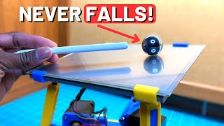
Inverted Pendulum - Arduino Balancing Robot

HTML-код
- Опубликовано: 18 авг 2024
- In this video I show off my latest balancing robot which is an inverted pendulum robot! In the video I explain how it works and also do a bit of a deep dive into some background in the area of control theory.
Background Info, Code, 3D Files, Parts List: iancarey.ie/do...
Code: gist.github.co...
3D Printing Files: www.thingivers...
Two Wheel Balancing Robot: • Arduino Self Balancing...
Ball & Beam: • Ball & Beam - Show & Tell
Detailed Control Theory: • Pendulum Control Theor...
Patreon: / careyi3
Website: iancarey.ie
#robotics #controltheory #3dprinting #electronics #arduino


howx the encoder measures the tilt angle
So there is a shaft at the base of the pendulum which runs inside bearings and is fixed to the pendulum. Onto this shaft I have mounted a quadrature encoder. So as the pendulum tilts, the shaft rotates. The encoder can measure the rotation, and so we can then work out the tilt angle.
Hello, I have some questions.
How does the encoder read the increment, does it have a slotted wheel?
Does the encoder know which direction the pendulum rotates?
Hey there, good questions! The encoder does indeed have a slotted wheel. It’s a very high precision one that is made of a very thin disc with tiny lines cut into it. The reader shines a light and records light and dark as the light shines through the slots. It actually does this twice as there are two reader heads in the unit separated by some distance. This is also how it then can figure out the direction of rotation. It’s what’s called quadrature, it reads the rising and falling edges of the pulses and so is able to figure out the direction. If you are interested in this look up quadrature encoders, specifically the encoder I used was a HEDS-9000 encoder.
@@careyian perfect, thank you very much
please help am doing project just like this...
Can you give me the diagram, I don't know how it is connected even though I have read your program, thanks
Hi there, I don’t actually have any wiring diagrams for it. I’d have to draw some up, will see if I have time to do it any time soon. However, the wiring shouldn’t be too hard, if you look up the wiring for a DRV8825 stepper motor and a quadrature encoder you should be able to figure it out.
@@careyian I can contact you via facebook or discord
iCan you give me the circuit diagram on paper, it doesn't need to be very complicated@@careyian
Nice project bro! I wonder if you have the schematic diagram of connections, could you help me out please?
Hey there, you can check out this link in the description for all the details I have published about it. iancarey.ie/projects/invertedpendulum
The only thing I don’t have is a wiring diagram, but if you look at the code it’ll have the pins I’m using in the Arduino, hopefully that helps a bit!
Thanks a lot for answer, but I'm looking for the connection diagram Arduino-Electronic components, I've been searching for in your website but I haven't found it. If you could help me with that I’ll appreciate it.
@@irvingheredia7575 hi there, such diagrams don’t exist I’m afraid.
I'm glad you had time to answer my questions, thanks a lot!
How do I create the swinging rod and can you pass the libraries you used?
Hi there, I cut a length of stainless steel rod I had to length and threaded the end. The weights are then just a bunch of washers secured with a nut. The washers allows you to tune the weight at the end however, if you don’t have access to thread cutting tools, the rod on its own will work just fine. One tip, the longer and rod and the more weight on the end of it, the easier it will be the balance. Hope that helps!
As for the libraries, you can find the code in the link in the description.
@@careyian Can u give me the diameter of the swinging rod?, I am making an inverted pendulum as a final project for a subject and we only need the part of the pendulum
@@GustavoelGamer it is 5mm
@@careyian I have finished with the mechanical part, only the programming part is missing. Do pins 6, 7, and 8 go to the stepper motor driver or to which components do they go?
@@GustavoelGamer 6,7,8 all connect to the microstepping config pins of the driver labeled m0,m1,m2. They are not strictly necessary, you can hard wire them for a single stepping mode. I did it this way so I could tune the stepping mode in code once everything was soldered together. If you are working on a breadboard it’s still handy but it’s not too bad to just move jumper wires around.
Can you do a double pendulum
Possibly!! Might add it to the list for a future project