PID Controller for Servo Motor explained: How does it work?

HTML-код
- Опубликовано: 15 ноя 2023
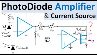
- A Proportional Integral Derivative Controller also known as PID controller op amp circuit is designed as Speed-Locked Loop for a Servomotor with two operational amplifiers and two capacitors realizing a closed loop PID controller to set the speed of the motor at the desired value and to keep the rotator speed error minimized. For more op amp circuit design and analysis examples and tutorials please see • Electrical Engineering...
In this PID servomotor tutorial and walkthrough example, the first op amp in this circuit is wired as difference amplifier to effectively implements a speed error detector similar phase error detector in a Phase-Locked Loop or PLL circuit. The second operational amplifier then receives this measured error at its input and then generates an output voltage comprised of three voltage terms in the form of Proportional Integral Derivative of the error. This PID voltage is then fed to the input of a power amplifier that is capable of generating large currents at proper voltage level (power level) to drive a PWM or Pulse Width Modulator that then adjusts the speed of the servo motor. A Tachometer or RPM-meter then mechanically or optically measures the speed of the motor (e.g. optical counters or encoders) and generates a voltage Vrpm that ideally should match the Vref that is the setpoint voltage at the input of the circuit that defines the target speed for the motor. A combination of Kirchhoff circuit laws KCL and KVL and op amp virtual short and inverting and noninverting amplifier gains are applied to quickly analyze this PID circuit and to find the transfer function.  Наука
Наука


This is the first time I ever see a PID with actual components instead of just math that makes my head hurt. 😄
Thanks for watching and your comment. Glad that you liked this PID Controller video. For more analog circuit examples please see: ruclips.net/p/PLrwXF7N522y4c7c-8KBjrwd7IyaZfWxyt
I hope these Circuit design and analysis videos are helpful. 🙋♂
This is a little new to me. So far I have dealt with PID Mass Flow Controllers, temperature controllers, and PLLs. As I understood the reason for using PID for temperature control was to prevent overshooting and undershooting and ensure the fastest possible correction. So the same principles would be applied here to the rotational speed of a motor?
As far as PLLs are concerned, I am and always been fascinated by them. I think they are absolutely marvelous pieces of electronic technology. Maybe worth talking about? Also, some discussion of the practicality of adjusting these coefficients in the PID controller would be very interesting. Anyway, thank you very much for this post. I didn't know how I would go about putting together that kind of controller before I watched your post.
Thanks for watching and sharing your thoughts. Glad that you liked this video and it is helpful. You are right, the same principles as PLL and as PID for thermal control are applied in this example.
Sure, hopefully soon I'll prepare another PID example discussing controller coefficients and practical choices for components. I will also prepare an example/tutorial for PLLs. Thanks again.
Thanks very much, the explanation of how the parts of the circuits worked and when they worked at different frequencies is nicely explained. I guess the fun time is always finding the good concrete values for any particular example :D
You're welcome. Thanks for watching and your comment. Glad that you like this video and it is useful. Well said 😄 yes, the fun challenge is the right component selection to keep PID controller stable and functional with proper response time for a given application. Alright, I'll prepare another PID example sometime soon discussing controller coefficients and practical choices for components. I will also prepare an example/tutorial for PLL as a related topic since this circuit is effectively a Speed-Locked Loop (SLL). Thanks again.
@@STEMprof you are very generous, thanks for your videos. I find most of the time even though they have the math applied, it's just enough that relates to the problem and is easy to see how it works, but yet still working from first principles. Other places either skip it entirely, are very surface level, or dive straight into deep theory so you'd need a book with examples to help you understand as well.
@@ivolol My pleasure, And thank you for watching and your kind words. I appreciate. I am glad that you like my circuit videos and you find them useful and practical. Thank you very much. 🙏🙋♂️
Thanks for nice explanation and the right amount of formulas. One thing I'm missing. I was really expecting to get some final formula based on R, C used in schematic, as a sum of 3 separated parts (proportional, integral, differential) as in basic formula. Basically to see the K parameters, which resistors and capacitors are influencing it.
Thanks for watching, your comment and good points. Glad that you like this video. Alright, I'll prepare a follow-up PID controller circuit example and video sometime soon discussing practical choices for components and controller coefficients. Thanks again.
Great! I'm already subscribed, so hopefully I won't miss new videos ;)
@@Chupacabras222 Thank you :) 🙏
Thanks for watching. For more Op Amp & Circuit Examples please see: Push-Pull Power Amplifier ruclips.net/video/866MYibo8yE/видео.html , Electric Circuit Analogy for Mechanical System: ruclips.net/video/997hfjGK3_w/видео.html
Flex Voltage Regulator Example: ruclips.net/video/CJl-urzeiTo/видео.html
Op Amp Analog Differential Equation solver ruclips.net/video/ENq39EesfPw/видео.html
Bandgap Video: ruclips.net/video/esMlNx5w9Jw/видео.html
Sawtooth Oscillator with Op Amp, JFET and BJT Transistors ruclips.net/video/5zHXTx-Vl20/видео.html
Full-Wave Rectifier: ruclips.net/video/DJJMNU-CYcg/видео.html
And Analog Circuit Design Video Playlist in my channel ruclips.net/p/PLrwXF7N522y4c7c-8KBjrwd7IyaZfWxyt
I hope the Analog Circuit Design and Analysis Examples are interesting and helpful. 🙏