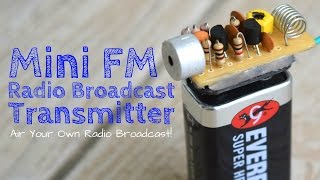
Weekend Projects - Super Simple FM Transmitter

HTML-код
- Опубликовано: 8 июл 2024
- Complete instructions for this episode of Weekend Projects can be found at makezine.com/projects/super-si...
Find more at the Maker Shed: makershed.com
Make: Electronics, 3rd Edition: www.makershed.com/products/ma...
FM transmitters can be complicated to build, but not this one - it's about the easiest you can possibly make. And though the science of radio is well understood, there's a magical, emotional quality about it that we don't often stop to appreciate. Building your own radio receiver - or better yet, transmitter - makes it real again. You will not forget the first time you pick up a transmission broadcast from a device you soldered together, yourself, from a few bits of copper, carbon, plastic, and wire.  Наука
Наука


This looks pretty easy and cool to make but when looking for the parts the only thing I can not find is...........a Radio Shack store!!!
order them from China, I bet i'll cost you less than 10$ and you'll end up with lots of spare parts
Hahahahaha solid
@@nuculabs it's a joke lol
If only we could say the same for Len Roberts, but unfortunately that dirtbag is still alive
*Super Simple FM Transmitter* is the latest addition to our beginner-friendly #WeekendProjects series powered by RadioShack: known as the "Manhattan style" for assembling circuits, use a copper-clad board as the ground plane and a small number of common components to build a local FM transmitter for your favorite tunes.
Thanks :-)
Awesome! Thank you for this!
Where would one attach an antenna, and how would one adjust the tuning?
David tanciat
David Tanciar
It's pronounced SolDER not 'SoDDer'...
And it's actually point-to-point or rats-nest construction.
if someone was wondering and had these questions in mind:
where exactly would u attach the antena for longer range? and how to set a station of where the audio would be broadcasted?
don't worry i found the answers for you.
1- You can solder the antenna on the "free pad" (video 3:16) where the transistor emitter meets the 10pf capacitor and 470Ohm resistor (yellow, purple, brown, gold)
2- The frequency depends on the inductance of the coil and the value of the 10pf capacitors. The easiest way to adjust the frequency, for example to move away from a strong local broadcaster, is to slightly squeeze or stretch the coil.
if you search online for coils and capcitors you will find a fromula that will help u get a frequency (thats what i remember from my electricty class.)
hope that helps
SelfGlassImage Thanks 🙂
SelfGlassImage , WOULDN'T THE ANTENNA BE CONNECTED TO THE COLLECTOR SIDE OF THE TRANSISTOR ?
I would think so as it goes to the coil
Can you replace the coil with a crystal oscillator to set the frequency of the transmitter?
@@superjimbo1945 The schematic is clear: RF Out (aka antenna) is on the EMITTER side of the transistor, exactly as Bariq H says.
I think that without proper explanations all those projects are useless. An explanation of how it does work would be the most important thing
Exactly
Quantos quilômetros?????
@@marcondecarvalho8241 ????????????????
@Phillip Boyd he is right, i dont wanna just slap components i actually came here to understand how a basic fm transmitter works
I know how to make an FM/ AM transmitter with only one Transistor and one resistor and one capacitor and one variable capacitor aka knob to switch frequencies
"Head over to your local radio shack"
Yeah those don't exist anymore....
There are a few left...
Sadly
if anyone knows actual chains that carry items like these, send me them names. im starting to get into tiny tech building.
3V0 you would be surprised what Walmart online offers
@@TheMcdrewb thanks!
20 years ago I purchased an FM transmitter for some several hundred dollars. It was 130 Watt and covered a good radius. We were running pirate radio at the time. I opened it up and noticed it was a copper board with lots of hand soldered through-hole components. To this day I've always wanted to rebuild that and it's what got me started in electronics all those years ago. It looked very much like this, but larger, and there were some amps etc in there too. Very interesting stuff.
no experience with transmitters, only from the pass 3 months I have been doing research on DIY transmitters and finally this is the only one that works for me. WOW i love it. I didn't have 2 10pf caps so I used 33pf and it still works. thanks.
Omg. This is what I needed. I searched everywhere but couldn’t find it. Thanks man. This just planted seeds in me for future bigger and amazing projects.
The stop motion in this video is so great. What a great creation great job.
Built this the other day. Suffers from drift a little bit, but works very well and the audio quality is also very good. Mine tuned out to about 108MHz.
if you're a live musician, and on a low budget, this is a great way to make a set of decent in-ear monitors. the old band i was in used something like this except it involved two walkie talkies with in and output signals. we just used a 1/4" jack to the output on our mixer, and connected that to the input of the walkie. then on the other, we connected a set of headphones to the output of the second walkie. worked great. being a drummer, these are very useful to help out. Great video!
Very well presented - right to the point. This is a great adjunct to the Make: article, which has a parts list. The Radio Shack PCB listed is copper clad on both sides, so to get it to "snap" apart like in this video, you have to score the line on both sides. Probably the trickiest part of this project is to initially find yourself on the FM receiver, but once found you can "move" the frequency by squeezing or expanding the coil. Thanks for posting this project, Sean!
this is exactly the kind of videos i want to see from you guys :)
yeah > me too :O
Yea! It was so easy to understand! M gonna make this for sciece fair done in our school
This is probably the best electronic circuit layout and demonstration I have seen. This gives a list of the tools you need and all the parts and even what they look like. This is something I would most certainly reference to in a college paper or any academic work.
Thanks for the coil winding tip! Have been an Amateur Radio Op since 94. Never seen this until now.
John
You could have explained the reason for each component...
That would be helpful and useful.
This. I was thinking why the coil is that length. why the coil is even there.
the coil is an inductor. Generally they help control the flow of current. The properties of the inductor depend on the physical properties of the coil. The length may be specific to that particular circuit
+Alan Diaz
Examples? That would make for the perfect explanation.
Valken gb😚😙😚😛🤡☹️😣😟📚📚📙📘🔗🔗🔗📘📘📔🗂🍠🥖🥞🥞🥓🍳🥚🍳🍳🥖🥞🥞🥖🍤🍤🍤🍐🎧🎼🎱🎱🎱🎱🎱🎱🎱🎱🎱🎱🏓🎱🏉🏉🏉🏉🏉🎱🏀🏀🏀🏀🏀🏀🎾🎾🎾🎾🏸🥄🍝🍜🍜🍲🍥🍥🍥♎️♍️♍️♌️♌️♌️♈️♈️♈️♈️♈️☯️🌠🌠🗾🌠🌠🌄🌆🌇🌇🌇🌄🌄🗾🗾⛪️🏛🌆🌆🌄🌆🌆🌆🏙🏙🏙🌁🌁🌁🌁🌆🏙🌠🌆🌇🌇🏙⛩🌄🏬🏬🏬🏬🏬🏬🏬🏬🏬🏣🏣🏬🏣🏢🏚🏢🏢🏢🏢🇳🇿🇳🇿🇳🇿🇳🇿🇳🇿🇳🇿🇳🇿🇻🇺🇿🇼👨👨👦👦👨👨👦👦👨👨👧👧👨👨👧👧🦌🦌🦍🦍🦃🦃🐑🐑🐊🐊🐋🐋🐋🐋🐋🐋🐋🐋🐋🐋🐋🐋🐂🐈🐏🍚🍚🍚🍙🍙🍛🍧🍙🍡🍘🍢🍛🍜🍜🌯🍔🌭🥜🌰🥜🌰🌰🌰🧀🥖🥜🥜🥜🥜🥜🥖🥖🥖🥖🥖🥖🥖🍯🍯🥐🥐🍯🍯🍯🍯🥚🥚🍳🥗🇧🇸🇦🇼🇦🇼🇦🇼🇪🇺
hip hip hurray my first FM transmitter is working,Thank you makezine , but very happy that it worked
Hi Bhavani, glad you built it ! Share a photo or video with us, we want to see !
at which frequency did it operate ? and what was value of electrolytic capacitor did you use ?
Glenn John Ogapong 105.5 Mhz to 106 Mhz , some drift is there and i used 10 uF electrolytic Capacitor Glenn
Bhavani Shankar Hey thanks for the response. I made this today, but unfortunately, I can't get it to work. I used a 1uF electrolytic capacitor. I've been retracing my steps, making sure that I didn't miss anything. It could be that my 2n3904 transistor is busted. I don't know ...all resistors are of correct values, ceramic capacitors also as prescribed (2 10pF and 2 0.01uF respectively). I might redo this.
Thanks.
Finally got it to work. It was a case of a a bad transistor. :-)
Good video. Old schematic. Usually drawn with 27k, 10k vertically as a voltage divider for biasing the transistor. Some might place a variable capacitor in parallel to the coil for tuning, not too big of a value or tuning will be touchy, just pops on the FM radio. You could place the variable cap across the transistor, from collector to emitter. Use of an oscilloscope would show the frequency change in the sine wave. A varactor diode could be used with a .01 cap anywhere a tuning capacitor is used. Tune with a 10 k pot. Add a 10k potentiometer where audio comes in for modulation control if input volume can't be adjusted. Left pot wire to audio source, center pot wire to input cap, (1-33 uf) and right pot wire to ground. Use an on line dipole calculator to figure out how long the vertical antenna needs to be for the frequency you choose. Go crazy and build a field strength meter! Get it close to your transmitter antenna to check radiated power. A needle moves as the indicator. Make sure you don't cause interference with radio, tv,'s, etc..Once I heard somebody talk over a juke box that was unplugged! Ham operator using too much power.
Found the engineer : ) thx for this comment and the info!
@@jhg1930 USAF ECM tech and 28.5 years at intel. I made transmitters like this for FM music broadcast in the barracks when I was over in England. Music from my reel to reel was fed to a transmitter. Fun times back then. I still make AM transmitters now and then.
@@DavidALovingMPF102 cool! I make them myself. They are fun to make!
I followed your exact method and sourced everything from Ebay and it was a success first time. I added a 5cm coiled copper for antenna, good quality broadcast up to may be 20 meters!! Thank you !!!
Hello, what type of transistor did you use in the circut, I am just curious because it dosent really specific in the video. Also, wher on it did you add the antenna?
OK, built it. I had zero electronic experience before this, but ordered the parts, followed the directions on the video to the letter, powered it up......and.......IT WORKS!!!
I goofed up a couple of things, but I can correct those. It's broadcasting on 105.3 FM. It only has a range of a few feet, so I'm going to add an antenna and see if I can get it to broadcast 15-20 feet. Took me a grand total of about 3 hours, but I had a blast building it. Thanks for this most excellent video!
Amazing. Its very simple compared to what i've build just recently. Thank you for sharing this videos.
Q ppp 0
This is so good quality. And relaxing i love the music
That's a blast from the past. My last local Radio Shack closed down several years ago.
its the basic key to the most advance transmitters awesome project
It reminds me about my childhood years in which I used to put an FM wireless microphone next to a speaker and play music and pretend that I have a radio station using a radio cassette as a receiver.
I'm pretty sure I have seen this one before, in Make's videos.
Alltought it is a cool project, you didn't explain how and why it works and if you'd want to plug an antenna where you would solder it.
Greetings from Finland!
Yes, what are the two (?) contact points for the antenna?
Great beginner's project to get acquainted with hobby radio transmitters. Thanks for sharing.
Great narration and flow! The use of stop motion really helped keep the visuals clean and focused.
Plugging a mono TRS connector into a MP3 player will short out one of the channels, which is not really what you want. Maybe it would be better to join both channels together using mid-valued resistors to a single mono signal and use this as the input to the transmitter
Many people like this, but would you please provide a practical demo of it.
I expected your music to be fired through that receiver the last few seconds :)
i have just watched but not yet worked on it... but from the illustration I KNOW IT WORKS. CONGRATS MUCH FOR GOOD WORK.
That was refreshingly hardcore for a project like this. Manhattan prototyping & all.
Well this is rather strange and awesome... I did just that and even used the same i pod and strangely i dont need the 9 volt battery for it to work it works by just pluging the audio cable nothing else!!
+Lukus Ekers
That is amazing. Personally, I think you don't need an extra battery for a radio already powered by a device with a battery.
It just boosts the signal
Does it work really
Anyone know the background song?
Thank you so much! I got mine running which is so awesome. It transmits around 93 MHz.
Definitely recommend replacing C4 with a 10-40 pF trimmer.
Hey could you help me out?
Well, may I?
I have no experience with radio, circuits, soldering, or anything necessary here really, but once I do a little research and understand all of the things he's using here I'm definitely going to attempt at this!
I feel like this would be good In public, right near another car. Just say "HEY! YOU IN THE RED SHIRT! STOP SMOKING THAT CIGARETTE!"
Or, you know, simply acknowledge they knew the negative decisions and honor the fact that they're their own person and you cannot force your will on anyone.
@@whackyjinak4978 xd
R/IhaveredditWoosh means it's a joke I didn't get.I understand he's trying to make a joke, and I understand it's coming from a mindset that's toxic. Period.
@@whackyjinak4978 exactly...
ruclips.net/video/hqIrzkPDtrk/видео.html
Wow, pirate radio! This will be great to know about for when the zombie apocalypse comes! Great video. I do wish one could control the broadcast frequency range, though...
That's why I watched it. It just seems like one of those handy McGyver type things that could come in handy just in case. Probably won't be zombies though, even though that would be cool.
Sadochrist
No, I don't mean movie zombies. I mean roving gangs of starving people after the economy collapses. But if I actually say that, people think I am some kind of crazy right-wing prepper. But then, I am, I guess...
freesk8 you can use tweek the coil for range, and write it down on the botton, so you know where you will have a specific range
Out of curiosity would a variable capacitor attached to the coil allow some variance in frequency?
pirate radio ...only to the next(neighbor) room. power's too low. And spurious oscillations in radio air.
See here: ruclips.net/video/vrFLGBU41Ig/видео.html
Awesome project. Thanks.
If love to see more audio projects kinda like this. Love Make videos. Can't wait for more
where exactly am i supposed to hook on an antenna?
or - could you make a video about this particular fm transmitter or fm transmitters at all, explaining how it works. i guess a lot of people would be intrested to see such video!
Big up! Great video!
the first conducting coil he made is a antenna. you can just replace that and check the +/- sign
yue wang
what i was trying to say is - if he teaches people how to build something, then plz explain which part serves as what and so on.
Solder piece of wire (for 88-108 MHz, 1/4 wave = 76 cm - center of the band) to first turn after 0.1 uF capacitor (after +ve of the battery). So, now you have 1 turn - antenna - 3 turns to the transistor.
I still don't know how this works.
I never expected this to work on the first go making it on breadboard.
Thanks for the nice and clear tutorial.
Next up, to find out how to tune the range of the thing.
I actually did the day after, by just trying and using a trimmer capacitor like in the original design.
can you help me
Gorgeous job,
Congratulations!
head over to your local radio shack. Hahaha ha sure if you can find one
It's good but you need a VARIABLE capacitor to establish a frequency of transmission. Without it you can fall into a frequency of a local radio station, and will be impossible to get out.
+XXVorteXX if the tx frequency interfears with a local channel, just increase or decrease the spacing btween the coil
Unfortunately my one is not working. how can I check the output..
You can tune the frequency by squishing or extending the coil to some degree...
It's a good idea to check the frequency with a frequency counter. Then you can easily tune to a blank spot on the dial.
Sitter du i fängelse eller har du en FM-licens?
Manhatten style construction, pretty cool. Thx for sharing
I sure miss Radio Shack in Canada again. Please send Radio Shack back to us. I miss it so much.
Awesome little build. Thank you.
If I wanted to make this 12 volts, what would I do?
I’d think you do the same thing just instead of the 9 volt connector you use 12 volt connectors
Rip radio shack
Very well done. Really enjoyed it.
Amazing.I'm going to make one. Thanks for your video
but how does this work?
Syed Ilhan that involves a lot of physics and maths. Pick up an electronics book mate
As far as I can tell it translates the RCA electrical input signal to an electromagnetic one where the song's information is present in the variations of the frequency of the EM wave which is the interpreted by a Radio recziver and re-converted to an electrical signal to an amplifier and then speaker. The different transistors, capacitors modulate the electric signal, Amperage and voltage so it does it job in an optimal way.
@@theswagnezone7286 HAhahhah. Reminds me of my electronics class
CAN U PLEASE give me the circuit diagram ... i've project in engineering
Good luck with engineering :)
+Doaa Hiwat
makezine.com/projects/super-simple-fm-transmitter/
+Doaa Hiwat not being mean but if you're in engineering, shouldn't you be able to make a schematic by just watching? I'm just an electrician and I drew it out
hello
Thank you so much. I truly appreciated your thoughtful video.
just finished making it working pretty good thanks good video
How about a FM receiver?
***** Use your mobile phone or radio?
tariq aziz Right, but how about building a RF front-end, low-noise amplifier, FM demodulator, audio amplifier to a speaker? Using a phone or radio carries no learning purposes.
You can totally google whatever you want to do and if that doesn't help, i don't know what would
tariq aziz What's wrong with suggesting a fun-to-watch video on FM receiver from Make magazine?
Absolutely nothing
OLD COMMENT SYSTEM!!
Same lol
Same lol
bro,thanks for this great project. my first transmitter and it works:-)
Could u tell me how much it costed in making project?
Thanks for the complete tutor :D
it is not interesting, interesting to understand how it works
Why didn't you tried on bread board ?
then the transmitter wouldn't be portable
if that much I interested try it your self
if you ddo it on breadboard inductivity will be high and frequency wont be strong enough
Because it probably wouldn't work. Too many parasitic capacities and inductions.
I like the way to PCB without plotting, acid melting, holes drilling !! A sort of mess but works for little circuits.
This is very very simple and awesome, very very good
can we just use simple perfboard for things like this.. this is a huge waste of time and effort to cut blocks of copper board.. I'm getting annoyed here
you can, but make sure you got the schematic correct, and, perf board can make the project smaller also...
yus use as ground connection a piece of solid copper wire runjing across the one side, where you later on can soldr ground wire's to, or, use jumperwire
No, you can not use perfboard for this, because it's parasitic properties are not suited to build circuits that operate in the 100 MHz range
this is a stupid way to make a circuit board.
It is actually a very good technique and ideal for beginners, and with certain circuits, this method would provide important shielding from interference noise.
The best content and video I have seen so far
I’m amazed at the world we live in now. Great video
This is awesome...great video
Excellent! Precise! Thorough! My Middle school kids could follow this.
Yooo ....!!!!!i used enameled copper wire nd transmittr is wrking successfully....
.
.thanxx a lot to +make
.
.my childhood dream of making a fm transmitter is completed by u ...
Successful!! Worked soo good!
Clear, concise instructions, and the superb camera work makes the video a pleasure to follow! This is a master class in how a how-to video should be done.
As a geeky kid almost 50 years ago I made this on my 100-in-1 radio shack kit. It worked so well and the audio quality was very good at over 100 feet away (with small antenna wire). I did not understand and still don't how the audio modulation worked on FM, since I thought I was making AM (amplitude modulation). Ah, radio shack. :>( 73 AB2ES
a very good project
I loved the idea of using the board without the need of printing the circuit!
Nice projek 👏
nice fm transmitter i convert into stereo with stereo encoder great sound 👍👍👍👍👍
Nicely works for me, I used 15 pF instead of 10 pF capacitors. And frequency is something below 90.
But I want to share my experiences; it drains battery very quickly.
great project bigboy
thank you so much sir that is the easiest way to build a fm transmitter
I did some quick calculations via multiple websites and found that this coil is 0.05 uH, and with a capacitance of 10 pF gets a resonant frequency of 225 MHz. This isn’t in the FM range, but maybe the circuit board / antenna provides a bit more capacitance. A little more guess-and-check and I found that you would need a value of 45 pF to get 106.1 MHz, and to get below that just increase capacitance with a trimmer.
awesome..thanks for this video .
Awesome video
thank you for the informative video..very simple looking indeed with the step by step guides given..what should I do to improve its transmission capability? replace the inductor with a bigger one or add some additional antenna?
wow wonderful and easy diy pcb
Love your videos
I built one like this many years ago, and at first I thought it wasn't working. But, once I had access to a frequency counter, I found that it was working quite well but not in the commercial FM band but instead it was too high and was in the aircraft band. Little bit of tuning and it was back to where it should be.
which component determines the fm station frequency? does the coil pitch has something to do with it?
This is like the best way to solder
YOU ARE GOOD MAN
Can you please explain the role of each of the components in the circuit for better understanding
Resistors are potential dividers. 10 pF collector to emitter capacitor is regenerative feedback. 10 pF from emitter to ground is bypass. 10 nF in parallel to two resistors are bypass as well so RF won't disturb the bias. Electrolytic capacitor is for coupling purposes. Transistor is an amplifier and inverts the phase by 180 degrees and remaining is done by the tank.
That's a nifty way to build a circuit!
Very simple for this very good
I have a degree in Electronics and Communication Engineering and we've never learned about this basic stuff.
All we did was play around breadboards and logic gates and embedded C bullshit.
I was sort of feeling insignificant and searched for this video and now I plan to make my own radio.
Thankyou soo much sir .
cool. thanks for sharing
Hello,sean regan I am giving special thanks to weekend projects I try this transmitter in science fair in school after the science fair when the result came I was selected out of ten students. But I take a heavy amplification transistor hence,its worksSo you should give a perfect value of transistor.
I built my own in a different way with a tuner (variable capacitor) but it can only transmit on the 108 MHZ frequency. The audio is very clear though not noisy.
Very cool!
works....well done