12V 10A switching power supply (with schematic and explanation)

HTML-код
- Опубликовано: 12 сен 2024
- The schematic in my DB of reverse engineered schematics:
danyk.cz/reverz...
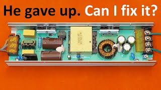
Today I made a teardown of an industrial switching power supply module S-120W-12 in a metal housing. The input is 100-240V AC mains and the output is 12V DC 10A 120W. It came from Ebay and it cost me only $8. In the listing it's called "switching power supply LED driver adapter", but it may have a lot of uses other than just powering LED strips. The SMPS is based on the old good UC3842 control chip, TL431 voltage reference and an 817 optocoupler. It has an open loop protection added, made of discrete transistors. It also has a softstart, a proper fuse, NTC thermistor, safety capacitors, snubber networks, EMI filters, good isolation distance and a relatively safe-looking transformer. The only problem of this switching power supply is the way the power transistor and diode are mounted on the heatsink! Just the sharp corner of it actually touches the aluminium plate! This video got quite long, but it's not easy to cover such a complex appliance in just few minutes. I didn't even get to explain why is the power supply clicking when in short circuit and why it may produce audible noise (whistling) if there was no slope compensation.
You can support me on Patreon:
/ diodegonewild
My Instagram:
/ savage_danyk


Excellent video on flyback switching power supply. I have 42 years of experience in the electrical and electronic field from power plant, consumer electronics, computer repair, aerospace CNC/NC maintenance, 17 years repairing and maintaining light rail commuter trains, attended 5 years of college of electrical engineering and numerous vocational and military schools. After saying that I want you to know you have provided answers to detail questions concerning switch mode power supplies which I have not been able to find. I have been working with switch mode power supplies for the last 36 years and have never seen this subject explained in detail and confidence the way you have done and now it’s all perfectly clear to me now from an design, engineering and repair point of view. The snubber network, continuous mode and discontinuous mode, the zener protection and the secondary regulation via 431 transistor using the voltage divider network is all perfectly clear to me now. Thank you very much for this video and keep putting out the videos. Knowledge and understanding of the buck, boost, flyback switchmode power supplies employing the principle of (Pwm) pulse width modulation is essential for today’s Technicians and engineers. Good job and I will be following you.
Dan really knows his sh*t, he would probably long be dead otherwise. Things he does with tesla coils are beyond crazy. But he really has a true deep understanding of how things work and what's still (reasonably:) safe and what's certainly better to avoid.
And he's patient. And knows how to simplify things for explanation, yet not oversimplify them. Those are makings of all the great teachers. 👍
Great description of how a SMPS power supply work. No one on youtube even comes close.
Thanks :)
Joseph Nicholas Exactly .
Joseph Nicholas Great!
Seriously
You should watch Jose caltum videos hi is Mexican speaking Spanish only
You have a lot of patience to reverse engineer this complex circuit. Thank you for all your work. I learned a lot.
Engineer with a caaat...
Who gives this video a dislike? Clearly a lot of time and effort has gone into reverse engineering and drawing up a schematic. Video like this are an excellent reference for repair and modification of these power supplies. Thanks mate. Keep up the good work!
Reverse tracing a circuit is something that not many people do today. And you explained it very well too. Thanks.
Agree. So this things called as "reverse tracing circuit" or "reversed engineering schematic".
I had done this experiment with THE REALLY SAME THING I've got from my college laboratory (SMPS S-100-12), and still I find it so damn HARD to reverse-scheme all the tracks when there are two sides in a PCB you should pay attention.
it's REALLY TRICKY.
and THIS MAN EXPLAINED IT ALL AS EASY AS HE SPEAK.
He is an expert.
Regards from Indonesia
and today, when I tried to do this "reverse tracking circuit" activity, my friend told me that it's something foolish things to do because they said it is pointless to track a complicated circuit, as long as we know how to use the device, that's crazy.
but i can't agree with them anymore, because here i found this man doing the same things as i did
@@stephenphen4349 Are you now experts?
As rpbajb said "You have a lot of patience to reverse engineer the circuits", and then to explain us how it works and also you point the remarkable points. Thank you for all your work. I also learn a lot. A stroke to the cat...
Very well done tear-down. I've designed switchers since about 1986 and am as shocked as you are about the poor mounting of the power semiconductors. On the other hand, I'm impressed that it didn't fail while you were testing it. After remounting those semiconductors properly to the heat sink, it's probably a solid little supply. Nice. Thanks for posting this.
I have several of these supplies that have been operating daily at about 80% load for about 4 years. I just had one fail so i took it apart and found 3 of the output caps had blown their tops off. Upon inspection I found they were 1000MFD 16V caps. Yes a 16V cap on a 12V power supply, I'm amazed it lasted this long! I replaced them with caps rated for 25V and were back in business. Thanks for an incredible explanation of how a SMPS works.
Excellent way of explanting better than University teachers, having understanding and clear concepts of Power Electronics, Electrical and Electronics.
this one of the best i've encounter of explaining the sampled SMPS
i just wonder why there are haters...
Thank you for the great break down on how these work, I'm still learning electronics & you have gave the best description on these & on others that I've seen on you tube now in several months, you really know what your doing & it shows greatly. Again thank you for the help, Tom.
Transistors also do double duty as short ciruit protection, as the feedback vanishes, but the loop will go to full power in an attempt to drive the output to get feedback. The transistors then reduce duty cycle to a low level that will not result in the power switch blowing up.
Soft start circuit starts up initially as zero volts on the capacitor, and this is slowly charged up by the 5V supply through the resistor, the diode to feedback ensures that the lower of the capacitor voltage or the feedback transistor is the one controlling duty cycle, and when the capacitor charges up to 5V it is effectively out of circuit allowing the feedback to be the control.
The poor mountring is typical, wrong lead dressing on the power devices ( leads cut short instead of being left full length) along with the wrong device locking tab, which is meant for a thicker power device, so is skew on the package and thus applies pressure to one side only. Best would be to shorten the leg slightly and put a silicone pad between the device and heatsink to improve thermal transfer. The 10A rating is likely the diode current rating, the long term rating would be 5A, and would be more so limited by the ripple current rating of the 3 output capacitors in the secondary, which probably only are rated for 1A5 of ripple current anyway. Probably will not have the longest life at 10A, likely to fail after around 2000H of operation, or 3 months of running full power 24/7, but running 8 hours a day might actually make a year before it goes bang as the output capacitors dry out and the control chip power supply capacitor goes high ESR. Fixed many of them with new capacitors on the output and those little 47uF capacitors on the primary side.
Yes, the PNP transistors are also usefull to detect an overload beyond regulation. As one of the viewers noticed, the power diode (and maybe even the transistor) are recycled from an e-waste. The diode has a mark from a screw. This is why it couldn't have longer pins. They were already cut short when they salvaged it from an old device. You're right, the 47uF capacitors parallel to the chip power are very notoriuously going high ESR. Also the output capacitors won't last very long. A forward topology would be better for 120W, because most of the ripple current is filtered in an (usually toroidal iron dust cored) inductor before reaching the output capacitors.
hello can you help me with uc3842 basics
Very well explained. Not even my college lecturer come close during his lecture.
Thanks or the in depth explanation. I found it very interesting how this power supply works. I enjoyed this video a lot....and the cat too. 😀
You explained this schematic very well-I learned a lot ! Thanks !!Greetings from Macedonia!
Probably the best explanation I've seen of the operation of a switch mode power supply. Great work! And thank the cat for pointing to the appropriate part of the schematic with the tail :-)
One of the best smps explanations. Just to add: nterference capacitors = mov. There are X movs and Y movs
tl431 here works like a opamp to form a type-2 loop compensator. It provides very high open loop dc gain so that the output is well regulated. The RC near tl431 form one zero and the 100nf capacitor on uc3842 pin1 contributes to 1 pole, together they provide up to 90 degree phase boost. A large enough phase margin is required to stabilize the power supply.
I only use this kind of power supply in my job.. which it’s work perfectly without any problems... the only problem is when it gets hot.. so cool it down and enjoy a high current, stable voltage, cheep power supply (:
Nice description and explanation, i love your videos, it’s very informative and you care about safety the most!!!
Love the kitty co-host! Can't believe the how poorly the heatsink is attached! Really lucky 14 amps didnt blow it up!
Units like this always have to be optimized after purchase. I've got used to open up all electronic stuff I've bought and have a look inside to see what has to be fixed before usage.
@@e1woqf i do this too when i buy cheap stuff , like if a buy a cheap psu i would always check the transistors and board cus sometimes they can put things wrong and cause problem ..
When It comes to SMPS this man has got PHD in it! He makes it so interesting to learn power supply and electronics! Have you ever seen cheap chinese supplies where capacitors CAP 's are leaked hole deliberately to save some money on buying large voltage capacitors?
This is the best expression of basic flyback circuitry with its all details. This is the good share for the beginners. Good job.
Great description of working of the power supply! And the cat is helping the class to relax...
Im on a journey of making my own flyback power supply using uc3843, your video really helps, i already made a isolated flyback converter as ground loop isolator, although it only rated for 12-24, now im trying to design the same as in this video
This is amazing! I am learning fast...I need to because my wife's beautiful, 17 year-old Yamaha Clavinova has stopped working. Just shows a blank green screen, and nothing else, dead as a maggot. So, thank you for the clarity of your presentation. I am in NSW Australia, and I love your accent.
Great explanation. Really helps me understand the UC38xx series, especially the open loop protection.
I have one of these and I never had the chance to perform some stress testing myself, thank you for sharing!
the clamp has benefits for the heatsink attachment. the bolt can distort the package and have the die separate from the tab internally. some manufacturers tried rivets instead of bolts, even worse.
Man! You're a GREAT teacher. Now I understand the basis of single switch forward converter. Thanks my man!
This is a flyback converter not a forward converter.
I'm loving these videos. Finally someone explains things properly.
Great job in teaching SMPS. Nothing comes close. You have put excellent effort. 🙏
Great video and surprising how cheap they can manufacture those power supplys
Thanks! This helped me change the output voltage on a similarly designed PC-C-090-130060CT AC Adapter by changing the resister values in the voltage divider.
Beautiful presentation - your help is greatly appreciated.
Love from Indonesia
I didn't know you had a RUclips channel. I've built a few SMPSs with the information I learned from your website.
It gave me the shivers not seeing you discharging the main cap :D
Wonderful breakdown. My issue with these power supplies is large components vibrating and breaking their leads. I'll typically secure them somehow.
I saw this breakdown as I was modifying the power supply to power a tethered drone; sending the wide-range dc high voltage up the small-gauge tether and regulating it on the drone.
One of the best explanations on RUclips!
Great video. Just got this ps here in Brazil with the name Rick 12 120. Exactly same circuitry, and was wondering where to start the safety check before installing it, as it will run 24x7 at 8.5 amps. You saved me time. Thanks and congrats for the great channel and videos. I've been watching it for a while now.
there should be open loop protection because the IC shuts down when VCC is too high, so in an open loop condition the feedback winding would give too much voltage to the IC supply pin and the PSU would shut down.
Najlepšie video zo všetkých... Veľmi pekne vysvetlenie princípu a všetkých detailov... Viac takýchto videí prosím :) Inak videá sú všeobecne veľmi dobré a zaujímavé, dobrá práca :)
I've got one very similar PSU, probably from the same manufacturer. It works quite nice and reliable for my workbench LED lighting. But there is one really severe drawback which I noticed when I was repairing an old FM Tuner. I was sure that the unit was in good working condition after repair, but I could not tune it to a radio station - until I turned off the LED lighting. So the PSU produces a lot of interference.
Really good work. Great combination of contemporary and vintage circuitry. Amazing depth.
It's not much of a combination.... it looks entirely so ninetees :).
are these type of circuits easy for you?
A great power supply for not only LEDs but also Halogen and Incandescent lamps.I have a question though. Can it supply power to a HID (High Intensity Discharge) lamps?
Thank you for the video with the schematics and detailed explanation of work, also you've mentioned the working frequency. It was mandatory to adjust it, because all UC384x clones have a little different frequency formula.
I was able to repair mine S-100-12 switching power supply!
some scope images of the output ripple and spikes would be much appreciated in this kind of videos
The lack of thermal paste is a very good way of insuring failure in the future. With a slight adjustment of the positioning and add thermal transfer paste will likely make this unit last a lifetime.
It may not need thermal paste, being that it dissipates only 10W. Figure, 0.5W in the diode bridge, 2W in the switching transistor, 5W in the output diode, the rest in various other parts like the transformer and the current sensing resistor.
very nice explanation.....i wish if you could pls explain each section in detail.....like how the snubber network works the feedback portion....etc.....things will get much clear...also how the two transistor works at the bottom
I am really amazed Mr Danyk you havnt built yourself a good lod bank using those resistors instead of hand wiring them together by hand each time. your a modern day Tesler I expect better from you
OMG , this is best reverse engineering SMPS details video , this is very informative to me , thank you so much for sharing this video .
Wonderful explanation of smps.Thanks.after the switching transformer how is pulse output converted to dc?
The efficiency of the PSU is actually better than I expected! The capacitors are cheap though ...
couldn't be explained better. thank you
I would like to see your own project "High power adjustable switching power supply (SMPS) 3-60V 40A" with 10-20A version of the PCB files and parts list. Thanks a lot for this video and your great effort!
Love your voice, your way to explain the thing, and your teammate:))
I already buy some PSU like that. In my country, it is called "beehives" power supply because of their looks.
Thanks for sharing!
Excellent video! I'm learning a lot about power supplies from you and finally start to understand the schematics of the complexer ones. Keep it up!
Great video. I'd like to see a movie with an oscilloscope, where you testing power supplies.
Thanks RUclips for suggesting this channel
So a unit that seems to perform well despite some questionable things.
To me the datcodes on the Nippon Chemicon main filter cap and the ON Semi control chip seem a bit too old to be genuine items. The unmarked diode and Chengx electrolytics (I thought it was ChongX, the Chinese seem to counterfeit even their own brands) tell the true story why this power supply costs only $8.
Little trick. If you reduce the value of the high ohm resistors going to pin 2, this supply will operate at much lower voltages on DC. Of course it will be lower current, but a nice isolated supply for solar. Much safer than a buck converter which are far and few between in the 50-90V range.
It is nice to see a fairly well made power supply. (Of course the heat sink issue must be addressed).
One thing to note - usually these supplies are built using used parts. For example you can see remains of heatsink paste on the back of the output diode :)
Very clever circuit for protection if opto is out. Is it work as current protection too?
Excellent presentation indeed. Nevertheless, in your schematic, the two current measuring resistors at the source of the primary switcing transistor seem to constitute a resistor of 0,235 Ohm/ 2W, as they are connected in parallel. But this value is wrong. These resistors must be 4,7Ω each, constituting a 2,35Ω/2W resistor. Otherwise, in order to reach the protection start voltage of 1V needed by the I.C. you would need 10 times higher amperage through these resistors, meaning (always theoretically) that the secondary current would soar sky-high. Besides, the switcing transistor would not be able to handle this current. You can easily verify this fact if you do the math. I believe that you misread the third resistor colour which I believe it is gold (I cannot distinguish it from the video) and you read it as silver (that is, the resistor code values, 4 and 7 successively, resulting in 47, had been divided by 100, resulting in 0,47Ω each, instead of being divided by 10, resulting in 4,7Ω for each one of them). But this is a minor mistake only. No major issue whatsoever. Good job!
thanks for your explanation but also I have a question isn't it weird that the feedback pin is going to ground?
@@baharazadi6289 No, you got it wrong. The voltage developed across the source resistor is the translation of the current magnitude which runs through the transistor and it goes to pin 3 of the I.C, in order to activate the protection circuit when this voltage reaches 1 Volt. The other end of the resistor, of course, has to go to the circuit ground, which is the common reference point for all voltages of this circuit...
@@user-pz6cx8zf2y I meant Vfb pin, which is connected to the ground(Pin2)
@@baharazadi6289 Because the designer didn't make use of the relevant internal circuit, but he chose to regulate the feedback voltage directly through the optocoupler circuit. The collector of the opto coupler has the control of the output voltage now...Not the stage the pin 2 goes to...
@@user-pz6cx8zf2y Thanks, I'm testing this circuit but don't get the answer yet. Do you try it?
I think everything in my circuit is exactly as he said in the schematic. maybe something is wrong in his circuit drawing
Nice video on switching Mode Power Supply.
Very good and practical way of explaining.
You could activate the subtitles to be able to follow his impressive explanations. Many thanks.
Amazing work of the schametic and desciptive video, thank you for creating it
Mohl bych tě poslouchat celý den, fakt pecka !
:))))))
Great explanation on how this smps works. Thanks, Maestro.
Recently found your channel. I'm very satisfied!
Thank for making amazing videos.
Sir can you make a video on how to select transformer for SMPS for an example I want to make 5V 2A SMPS then what value of inductance and how to choose transformer for it..
The primary capacitor is a nice nippon chemi-con (quite expensive for this price, i'm surprised)
thank you for dedicating your time in order to share knowledge
This is exactly what I was looking for, thanks !!
Great video ! Congratulations.
It is very usefull for manny people. I have used it to modify the range of voltage adjust of my power supply.
Thank you.
i like your accent because i can easily understand your explanation,thanks.
Looks like the diode was recycled since it has a screw mark on the tab.
But it could have been worse, I bought one of the small laptop ones for a project and not only diode and transistor were recycled and not touching the heatsink, the input capacitor was also recycled and all three were dirty and with remains of heatsink compound they previously had.
You're right! I didn't even notice the screw mark. So the diode is recycled from e-waste. This also explains why the pins are too short.
Still a master piece in 2024...
Nice video !!
Are you sure the efficiency of flyback without synchronous switching can reach 92 % ? even the best buck and boost converters in the marker struggle to reach 90 % without synchronous switching and here we have an isolated flyback topology.
I also have this model of psu however after a long amount of use the output became 4vdc instead of 12vdc, could it be the transformer?
I just received very similar one, but 48V/4.2A. It has only 50V caps at the exit, while the output can be adjusted higher than that!
At least all the components seem to be new.
What kind of range would you get if you swap adjustment resistors, and output capacitor? What is the minimal voltage you would get?
Bless you. Thank you for the reverse engineered schematic. Much appreciated.
Maan, you're pretty great. Thank you so much for explaining it so clearly. It helps me A LOT while i'm learning that kind of stuff. High five, my close neighbour, high five comes to you from Poland! ;)
hi, any idea how to control output current for a CC type option
Very Nice explanation. Thank you so much dear. I have downloaded your video i will watch it again and again to understand it more and better.
Muchas gracias por tan explendida forma de enseñarnos tanto en prueba como teóricamente el funcionamiento de la fuente!!! bravo!!!!
Superior description
Great Great Great description I found it very interesting how this power supply works. I enjoyed this video a lot Love from morocco
very nice explanation DiodeGoneWild. Hope you also do Cordless Tools Battery chargers voltage conversion from 120V to 240V such as Ryobi, Ridgid (AEG), Kobalt. These chargers don't have voltage dividers (after the bridge rectifier), so I don't know if conversion is possible.
I have never seen those :). I am surprised that purely 120V switching power supplies are still being made those days :).
Great work, fantastic presentation and formulas - thanks for sharing!
Beautiful cat! I love the markings.
We have that adapter in our church. Used for LED lights at the stage.
I just subscribed today and there's a lot of catching up from your videos. Hope i finish and undrrstand all of it in a month or 2. 😁😁
Wonderful demonstration! Thanks.
Why bridging the common and ground provides more safety? I thought it is safest to isolate it from the mains.
And another question: where can I read about open-loop protection? A simple google search does not yield the relevant result. Maybe it has another name?
hello excellent video, but I have a doubt, at minute 3:49 you measure the input power using a multimeter but I see that you use the mV range, I would like to know how to measure watts with a simple multimeter, thanks
Wow..!! Cool depth of knowledge... nice information about working principal of smps in one video.!!! 👌👌👌
Hi, Thanks for this video, superior explanation for the circuit flow and functions of the circuit.
I just got similar power supply, installed to supply cctv, for one year now.
Recently, it have problem that the supply drops as low as 2 vdc.
Without load will give 12+ vdc.. Can you spare some hints for the cause of the problem.
Any way, I replaced the power supply and the cctv operated back to normal.
I just want to repair the circuit to learn some trouble shooting.
You always make the best videos. Great job and cute cat 🐈 :)