Always love these tear downs. The old stuff is really interesting as well as it shows us (specifically people like me who don't know) how things were done back then. Gives us a bit more appreciation for the leaps ahead in technology we've made over time.
EEVblog Of course you can't please everyone when many have very different requirements. For me, this was a perfect teardown/repair video... but that's just me (and 300+ others). (Personally, I suspect that flat flex cable. Got to be dodgy after 4 decades).
EEVblog Why you´re even thinking about those folx, if someone does not like it, go leave....and look for something different.... You doin´just great!! keep on!!!
HEY! I'm new to this youtube thing, and have watched Dave's earlier videos too. This is my take from "fresh eyes." The man has made 663+ videos, and is still coming up with good, interesting topics. People send in their stuff for mail bag day, to see Dave tear it down, often with other requests. (what he is doing here) There is a big audience here, and all want to be appeased. So finding a balance point to please all is not so easy. I know some say he is drifting; I would rather say he is diversifying to please a growing audience. Constructive criticism can often be destructive to ones moral. If you weigh the positive comments to the "so called" constructive criticism, we can see the positive comments prevail. Dave has taken "Geek" and made it Cool! This is the reason you are here watching "and reading" this now. My advice to Dave is, don't drift from the path your on. (All those subscribers can't be wrong!) I "personally" like the diversification, and from what I can see, so do most others here. SO...... Keep up the good work Dave!
I concur. If so many on here are EE's, why aren't they busy designing and building their own stuff instead of complaining that Dave isn't doing enough of the work for them? Just my 2 cents...
I am SO glad someone sent you one of these! I have a pair of similar models, but rebranded as Monroe. One working, the other not. The working one is a Monroe 344 Statistician, with dual program banks. I'll definitely be paying attention! Excited to watch this teardown! :D
For what it's worth.. Dave, I like your videos very much. I am the type of person that when something doesn't work, I like to tear it apart and fix it. I enjoy watching you trace the circuits and replace the bad parts and such.. Keep up the great work.. I stumbled across your channel the other day and I am now a subscriber and looking forward to your next video.. Shoot.. I am even looking around my garage and bins to see if I have anything to send you that you would get a kick out of..
Another good video, Dave, even if you didn't manage to get the display up and running. Sometimes we learn just as much from our unsuccessful attempts as we do from our successes. On a side note and following on from some other comments below: I've been following these for ages now and still enjoy the content - whether that content is high or low brow. Your series on microphone design and construction was fantastic and will be a valuable resource for those working/teaching in this area. Keep up the good work and keep those videos coming, whatever they contain :O)
That's a Burroughs corp. display!, wow!, my father used to service burroughs computers, i remember them taking one apart in the 80s, they had to do it on the front yard of our house, at least 4 people worked on it it!, each "section" was a steel frame at least 2m wide, we kept those to make awesome tables, and some of the power supplies(~25KG linear transformer and some 70000uF siemens caps that are 20cm tall)
Great video Dave. And just so you know, I love your channel, still watch everything you post when I can, and I love the direction its going in. Just wanted you to know that there are people with you still, haha. :) Also being a fellow Aussie I will get down to come and visit you one year at a show.
The D-scan board is probably not only for the display, it's for the keys, too. So one DIP40-chip for Display, and one for Keyscan. The dead cap is probably a wet-slug tantalum, failing miserably and spilling it's corrosive contents ... The "Panaplex II"-display needs around 180V to work, so your 100'ish V is too low.
No point in risking busting one of his better scopes' inputs poking around unknown voltages when he has an older spare that is still more than adequate for the job.
We really want to see what that funky display looks like. Hopefully, you can bring this beast to life, or at least hack the display panel to light some segments.
Great vid as always. I recently got a BM257 from franky, very happy with the service and the meter. I'd like to see you do some nice useful project builds too.
Could you just look at the board with thermal imager? Do you have it? It should be obvious where this extra current is dissipating, without probing each part...
Hi Dave, Much to my amazement, I strolled on into Jay car in Alexandria and sitting in one of the boxes amongs all of the parts was.... wait for it.. 3 x 12 digit plasma displays for around $15. So, if you want to make your way there, you might find a replacement for that old bugger.....Or I can grab em and drop them do Doug, if you so choose
Hey Dave, here in Canada I've got the same meter your using in this video. Except.. Its branded Greenlee. Model DM-200A. The only difference between them is yours has the cap feature. Mine has plugs where the REC and CREST buttons are. I wonder if I could enable this capacitor feature? Cheers.
Shouldn't the company making the calculator have noticed the power consumption as an issue that needs to be fixed when they noticed any of them pulling even 1.3 amps? The battery life must have been horrible.
What is so unexpected out of a 70s-vintage calculator drawing over 1A? TTL logic is a power hog and VFDs too. That thing uses D-cells and an external power adapter for a reason.
in 1973 a calculator was amazing, and my 1978 pocket calculator on 4aaa (expensive at the time) i think last 2-3 hours of use!, horrible battery life was typical
Daniel Sauvageau Actually, those were Panaplex displays (I believe made by Burroughs). They have more akin to plasma displays or nixie tubes than VFD. VFD can typically operate on as little as, what, a15-50 volts, I think. These required a supply in EXCESS of 200+ volts to glow. They were full on gas discharge displays, not phosphor displays.
Star Gazer CMOS/FETs were not invented due to TTL using lots of power. BJTs were discovered while researching FETs - BJTs were an incidental discovery. Researchers always aimed to create a voltage-controlled current source (FET) but ended up discovering a current-controlled current source (BJT) first. By the time the first successful FETs were produced, BJTs were already widespread.
Its a neon display like in pinball machines. They don't have a heater. If the gas is gone they will draw zero current. Current only flows when there ionized. (Remember nixie tubes)
What happened to mailbag? Did it have a power button or a clear button try holding down the clear button I had a really old calculator once and to turn it on you had to hold down the clear button.
I am not surprised at the power usage. Back when that was made, all calculators came with an alternate A/C hookup. Most calculators did not even use batteries. I doubt that calculator was in wide production. It may have been a prototype. My father bought a calculator in 1972 for $40. All it could do was the four basic operations. No memory button. You had to handle subtraction like this: Instead of 10-2 = , you would enter it in as 10 + 2 - . If you divided by 0, the display would go out (the calculator didn't know how to handle it), To give you an understanding of the cost, in 1972, my father could take the entire family out (two adults and two children) for $5. Prices stated dropping for calculators around 1978 and batteries lasted longer (about two hours usage). I think it would be safe to estimate that calculator cost (at the time of production) to be at least $1000.
There are photos of IC dies at the oldcalculatormuseum and description of the TCL ICs at the datamath calculator museum. I tried to post links but youtube doesn't show posts with links, it also doesn't tell you they won't show up.
love your videos. can you review some of the home solar panel devices. I would like to see one on inverters like Harbor Freight and Power Bright, Aims etc. The average user has no idea if these products are any good. Thanks.
Nice video, his that an amd chip on the psu board ? Didn't know they were in business back then. It's likely that the display just outgas, i have the same type of displays on my pinball machine (williams system 9) and they are known for going bad. They operate at the same voltage (+/- 115v). Finding a replacement display won't be easy but you never know
Keep up the great Videos like this one David. I Love tease types of tear-downs, if you can please post more "troubleshooting Videos" similar tho this one. I love them. They are how most of us old timers learnt about electronics anyways. Test, and trace method. Before you could just Google up a schematic on the web.
Dave, I'm with you from the first of your videos. I discovered your channel when you released your second EEVblog video. Sadly I skip more and more of your videos without watching them as this channel is going on a different patch then my personal likeing. Those evenings when I made cup of coffee before your videos and watched them with smile on my face are gone. I understand that you need to make your living and gain more views by making your videos less specific and suitable for more people but still I wanted to say it laud, maybe you will see this comment. In my opinion this video blog is becoming more and more populist bla bla bla and going away from it's roots. I don't target these words to this video particularly but this is more about my recent feeling about this blog. I wold like more designing of electronics, more practical experiments, more fundamentals and tips explanation via practice. More modern and exotics electronics tear down.
I pretty much agree. I don't dislike the videos coming out at the moment, but I would love to see some more teardowns of high-end test gear, and maybe another design series, like the power supply one.
Hello Dave and the rest.. Exactly my opinion, now I know that it was not only my feeling that viedeos are moving another direction. I watch all videos from the first one. Dave has right to change focus and area of interest of this (his!) channel, I agree and no offence there. But it is true that now I'm searching for more content where is some deeper investigation/design of electronics rather that unboxing mail and teardown without deeper investigation. I finished studies and working 2 years in electronics industry and have no more time to play/hack/reverse engineer stuff at home so at least I'm searching for this content online so I can get small excitement when I wach someone else :)
Well it's his channel and his content is up to his liking. Maybe he's got a broad interest in electronics (as he shows) and not specific like you want. IF that's the case, then just skip over the vids you don't like and quit complaining. The man works his ass off with a full time job and does these in his spare time. We have to give him kudos and applause for whatever he puts out. Heck, he could just say bugger you lot and go home and play with his kid. But he's putting in extra time at the lab to show us interesting things. I appreciate what he does. And i'd argue, you should to. Again, just skip over the ones you don't like and spare us the commentary about how it's not aimed specifically at your interests. These sorts of comments always annoy me. It's not your channel, it's his channel. If you want specific content, make some videos and contribute.
This thing shows what a huge industry calculators were before you could buy one for $5. You could stick four boards on a backplane and sell it for $300.
I'm Norwegian aswell, and I think those probes are Probemaster 8000 series (www.probemaster.com/product_info.php?cPath=2_12&products_id=198) The best bargain on these is here www.ebay.com/itm/Deluxe-Probe-Master-DMM-Test-Lead-Set-NEW-8043S-/360984481528?pt=LH_DefaultDomain_0&hash=item540c5a0ef8
Those caps are polystyrene with aluminium foil so the residue is aluminium oxide. These caps were prone to this problem as they absorbed moisture. Horrible things but all the rage in their day!
Dave, I found this vague reference to the Boroughs PDP displays in the link below; it mentions that calc too. It strikes me (pun intended!) that it would be easy enough to check the cathodes are being pulled down in sequence and the anodes taken high... maybe the display is goosed :( In which case, you could probably replace it with a row of Nixies with no circuit changes; getting it back in the case might be interesting! :D www.vintagecalculators.com/html/calculator_display_technology.html
Here's a copy of the info on the site: First TI chip set produced for Sumlock-Compucorp This huge chip set was developed by the engineers of Compucorp and produced by AMI. Later TI qualified as a second source to AMI. The chip set forms one of the first programmable calculators, the Compucorp 324G Scientist. Type Year Function Calculator Comments TMC1864 1971 TCL08 - Display Compucorp 324G Replaced by TMC1884 TMC1866 1971 TCL06 - Data Processor board TMC1867 1971 TCL05 - Data Processor board TMC1868 1971 TCL01 - Printer Compucorp 325 Printer driver TMC1869 1971 TCL02 - Keyboard Keyboard-scanning electronic TMC1870 1971 TCL04 - Data Processor board TMC1871 1971 TCL03 - ROM Interface to RAM and ROM TMC1872 1971 TCL07 - Data Processor board TMC1884 1971 TCL08 - Display Display multiplexer
You display the same saddening disregard to 1973 technology as Dave does. I can't understand why anybody would compare a piece of 40 year old technology with today's stuff, and then make "amusing" remarks about the item. Would you (or Dave) do the same with a vintage car from that time period? Compare it with a 2014 car and then complain and make ridiculing remarks about the vintage car? This was top technology at the time. I think Compucorp was even a few years ahead of HP. Please have some respect. We are dwarfs standing on the shoulders of giants.
NicsStuffmedia Some ASICs/gate arrays back in the day used CML (current mode logic), the transistors were always in their active regions and they all got warm to the touch in normal operation.
If anyone is interested in the CPU it uses, I found die photos online. www.oldcalculatormuseum.com/d-compucorp.html Descriptions of the individual TCL chips found here www.datamath.org/IC_List.htm
Some info' on the chipsets - www.datamath.org/IC_List.htm#First%20TI%20chip%20set%20produced%20for%20Sumlock-Compucorp and some similar machines - www.classiccmp.org/calcmuseum/compucorp_portable.htm
That's a Burroughs corp. display!, wow!, my father used to service burroughs computers, i remember them taking one apart in the 80s, they had to do it on the front yard of our house, at least 4 people worked on it it!, each "section" was a steel frame at least 2m wide, we kept those to make awesome tables, and some of the power supplies(~25KG linear transformer and some 70000uF siemens caps that are 20cm tall)


Always love these tear downs. The old stuff is really interesting as well as it shows us (specifically people like me who don't know) how things were done back then. Gives us a bit more appreciation for the leaps ahead in technology we've made over time.
***** Thanks, I think so too. But it seems that 40+ people in the above comment don't agree :->
EEVblog Of course you can't please everyone when many have very different requirements. For me, this was a perfect teardown/repair video... but that's just me (and 300+ others). (Personally, I suspect that flat flex cable. Got to be dodgy after 4 decades).
EEVblog
you cant please every one every time. you can make difrent videos pleasing every one from time to time ;)
EEVblog Why you´re even thinking about those folx, if someone does not like it, go leave....and look for something different....
You doin´just great!! keep on!!!
HEY! I'm new to this youtube thing, and have watched Dave's earlier videos too. This is my take from "fresh eyes." The man has made 663+ videos, and is still coming up with good, interesting topics. People send in their stuff for mail bag day, to see Dave tear it down, often with other requests. (what he is doing here) There is a big audience here, and all want to be appeased. So finding a balance point to please all is not so easy. I know some say he is drifting; I would rather say he is diversifying to please a growing audience. Constructive criticism can often be destructive to ones moral. If you weigh the positive comments to the "so called" constructive criticism, we can see the positive comments prevail. Dave has taken "Geek" and made it Cool! This is the reason you are here watching "and reading" this now. My advice to Dave is, don't drift from the path your on. (All those subscribers can't be wrong!) I "personally" like the diversification, and from what I can see, so do most others here. SO...... Keep up the good work Dave!
Mr Carlson's Lab Thanks for the support!
I concur. If so many on here are EE's, why aren't they busy designing and building their own stuff instead of complaining that Dave isn't doing enough of the work for them? Just my 2 cents...
Robert Calk Jr.
true!
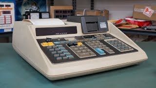
Wonderful example of 70's tech. Thanks for sharing the teardown.
I am SO glad someone sent you one of these! I have a pair of similar models, but rebranded as Monroe. One working, the other not. The working one is a Monroe 344 Statistician, with dual program banks. I'll definitely be paying attention! Excited to watch this teardown! :D
Keep doing what you're doing Dave really great videos.
For what it's worth.. Dave, I like your videos very much. I am the type of person that when something doesn't work, I like to tear it apart and fix it. I enjoy watching you trace the circuits and replace the bad parts and such.. Keep up the great work.. I stumbled across your channel the other day and I am now a subscriber and looking forward to your next video.. Shoot.. I am even looking around my garage and bins to see if I have anything to send you that you would get a kick out of..
Dave, don't you have a nice thermal imaging camera that FLIR sent you? I can't imagine anything better for finding shorts and overheating components.
Another good video, Dave, even if you didn't manage to get the display up and running. Sometimes we learn just as much from our unsuccessful attempts as we do from our successes. On a side note and following on from some other comments below: I've been following these for ages now and still enjoy the content - whether that content is high or low brow. Your series on microphone design and construction was fantastic and will be a valuable resource for those working/teaching in this area. Keep up the good work and keep those videos coming, whatever they contain :O)
That's a Burroughs corp. display!, wow!, my father used to service burroughs computers, i remember them taking one apart in the 80s, they had to do it on the front yard of our house, at least 4 people worked on it it!, each "section" was a steel frame at least 2m wide, we kept those to make awesome tables, and some of the power supplies(~25KG linear transformer and some 70000uF siemens caps that are 20cm tall)
The fun of taking apart antique electronics! :)
Great video Dave. And just so you know, I love your channel, still watch everything you post when I can, and I love the direction its going in. Just wanted you to know that there are people with you still, haha. :) Also being a fellow Aussie I will get down to come and visit you one year at a show.
The D-scan board is probably not only for the display, it's for the keys, too. So one DIP40-chip for Display, and one for Keyscan. The dead cap is probably a wet-slug tantalum, failing miserably and spilling it's corrosive contents ... The "Panaplex II"-display needs around 180V to work, so your 100'ish V is too low.
Quite late here, but isn't that most likely the reason for the seperate power cable? They didn't want to have the HV on the backplane?
Display manufactured in the 48th week of 1972 - that's a week before the launch of the final Apollo mission.
Keepin it real with the 1052e again. Nice!
No point in risking busting one of his better scopes' inputs poking around unknown voltages when he has an older spare that is still more than adequate for the job.
it was just the closest scope to hand. and I do know many like me to use it too.
Nice teardown and quick overcurrent fix...
We really want to see what that funky display looks like. Hopefully, you can bring this beast to life, or at least hack the display panel to light some segments.
USWaterRockets Orange! It'll look similar to this one: www.classiccmp.org/calcmuseum/Compucorp344.jpg
Another great vid Dave! Seems people are complaining. My only gripe is I NEED MOAR!!!
Nice videos Dave! Always learn something new :)
Great vid as always. I recently got a BM257 from franky, very happy with the service and the meter. I'd like to see you do some nice useful project builds too.
Thanks from a DIP lover
1st, maybe
- those the same gas plasma's as the old pinpalls?
Intel and AMD in the same device
Yeah i also noted that! Didn't even know that amd even existed back then..
voltare2amstereo Intel and AMD are pretty close, even nowadays with the x86 and x86-64 licensing deals
Thermal imaging camera could reveal the component that takes too much current
Hi Dave,
when you probe around with the scope do you choose the scope by reason, or just grab the first one that's close to you at that moment?
lg
Wauw, the display was made in exactly the same year and week when I was born.
I liked it better when you kept whether you could repair it or now a surprize :)
I was surprised that there wasn't any bypass caps at each chip like we did back in the day....
Could you just look at the board with thermal imager? Do you have it? It should be obvious where this extra current is dissipating, without probing each part...
Discharging caps is the only thing I've used the Low Z mode for on my U1272A, good advice!
unless you are a sparky, yeah probably the main use!
You might try your thermal camera to check if some of those TO92 transistors are getting hot.
the UHP480 chips look like they have a discolored pin, its possible when the capacitor shorted it blew the display output ICs.
Must be 4 bit CPU, those are 1kx1 RAMs.
Hi Dave, Much to my amazement, I strolled on into Jay car in Alexandria and sitting in one of the boxes amongs all of the parts was.... wait for it.. 3 x 12 digit plasma displays for around $15. So, if you want to make your way there, you might find a replacement for that old bugger.....Or I can grab em and drop them do Doug, if you so choose
I agree with others who said that the display needs around 200V to operate.
you could try to clean the contact on both the board and the connector. Also there is activity on the display bus?
21:56 Can you spot the broken solder point? :)
+MyCrazyGarage im sure that resistor didnt need to be their...
Why not pull out the thermal imaging camera and find the hot part?
I'm thinking pointing an IR camera at the board would tell you where the problem is.
7:11 - whats that AMD chip?
Hey Dave, here in Canada I've got the same meter your using in this video. Except.. Its branded Greenlee. Model DM-200A. The only difference between them is yours has the cap feature. Mine has plugs where the REC and CREST buttons are. I wonder if I could enable this capacitor feature? Cheers.
You should probably replace all the caps. I bet they're all not far behind the dead short ones.
Was thinking the same.
yeah was thinking the same.. a lot of them had the white stuff on it
Shouldn't the company making the calculator have noticed the power consumption as an issue that needs to be fixed when they noticed any of them pulling even 1.3 amps? The battery life must have been horrible.
What is so unexpected out of a 70s-vintage calculator drawing over 1A? TTL logic is a power hog and VFDs too. That thing uses D-cells and an external power adapter for a reason.
in 1973 a calculator was amazing, and my 1978 pocket calculator on 4aaa (expensive at the time) i think last 2-3 hours of use!, horrible battery life was typical
Daniel Sauvageau Actually, those were Panaplex displays (I believe made by Burroughs). They have more akin to plasma displays or nixie tubes than VFD. VFD can typically operate on as little as, what, a15-50 volts, I think. These required a supply in EXCESS of 200+ volts to glow. They were full on gas discharge displays, not phosphor displays.
Razor2048 That's why they invented CMOS about 4 years after this calculator was built.
Star Gazer CMOS/FETs were not invented due to TTL using lots of power. BJTs were discovered while researching FETs - BJTs were an incidental discovery. Researchers always aimed to create a voltage-controlled current source (FET) but ended up discovering a current-controlled current source (BJT) first.
By the time the first successful FETs were produced, BJTs were already widespread.
Check the displays heater. If the display has a crack,and the vacuum is gone,it will draw more current.
Its a neon display like in pinball machines. They don't have a heater. If the gas is gone they will draw zero current. Current only flows when there ionized. (Remember nixie tubes)
Are these hand laid traces? How did this world? How were boards like these manufactured anyway?
What happened to mailbag? Did it have a power button or a clear button try holding down the clear button I had a really old calculator once and to turn it on you had to hold down the clear button.
I am not surprised at the power usage. Back when that was made, all calculators came with an alternate A/C hookup. Most calculators did not even use batteries. I doubt that calculator was in wide production. It may have been a prototype.
My father bought a calculator in 1972 for $40. All it could do was the four basic operations. No memory button. You had to handle subtraction like this: Instead of 10-2 = , you would enter it in as 10 + 2 - . If you divided by 0, the display would go out (the calculator didn't know how to handle it),
To give you an understanding of the cost, in 1972, my father could take the entire family out (two adults and two children) for $5. Prices stated dropping for calculators around 1978 and batteries lasted longer (about two hours usage).
I think it would be safe to estimate that calculator cost (at the time of production) to be at least $1000.
There are photos of IC dies at the oldcalculatormuseum and description of the TCL ICs at the datamath calculator museum.
I tried to post links but youtube doesn't show posts with links, it also doesn't tell you they won't show up.
Also, there's no TCL-01 because that's the printer driver chip, which isn't on this model. :)
love your videos. can you review some of the home solar panel devices. I would like to see one on inverters like Harbor Freight and Power Bright, Aims etc. The average user has no idea if these products are any good. Thanks.
enjoyed that..cool..
Interesting to see that there were hidden switches on the keypad....
The Intel P2102 are 1024 by 1 bit NMOS devices.
Funny how large everything was back in the 70's. That same calculator today would be only a fraction of that size.
Nice video, his that an amd chip on the psu board ? Didn't know they were in business back then. It's likely that the display just outgas, i have the same type of displays on my pinball machine (williams system 9) and they are known for going bad. They operate at the same voltage (+/- 115v). Finding a replacement display won't be easy but you never know
oldmac6 AMD was founded in 1969.
If something is consuming 6 watt or so, cant you just use your finger to check which component is hot?
6:55 is that really an AMD chip? sure looks like their logo
could have used a thermal camera to find out the Component that draw a lot of power....
Keep up the great Videos like this one David. I Love tease types of tear-downs, if you can please post more "troubleshooting Videos" similar tho this one. I love them. They are how most of us old timers learnt about electronics anyways. Test, and trace method. Before you could just Google up a schematic on the web.
Dave how do you like that Rigol scope? As a poor EE student I can't afford an Agilent or Tek but can find those Rigols cheap even when brand new.
PorkChopify Buy the new Rigol 1000Z series, it's only $399 for 4 channels and a ton more functionality and speed!
EEVblog Thanx Dave, i´ll give one of those a try...
Maybe the display has lost it's vacuum?
To my feeling the audio is quite damped but im not quite sure. At least its not good... After 3:22 its okay again
LSI's? Hmm what are those? Not familiar with that initialism. :O
Large Scale Integration = tens of thousands of transistors per chip.
Legal,gosto muito dessas maquinas antigas.vlw!!
Dave, I'm with you from the first of your videos. I discovered your channel when you released your second EEVblog video. Sadly I skip more and more of your videos without watching them as this channel is going on a different patch then my personal likeing. Those evenings when I made cup of coffee before your videos and watched them with smile on my face are gone. I understand that you need to make your living and gain more views by making your videos less specific and suitable for more people but still I wanted to say it laud, maybe you will see this comment. In my opinion this video blog is becoming more and more populist bla bla bla and going away from it's roots. I don't target these words to this video particularly but this is more about my recent feeling about this blog. I wold like more designing of electronics, more practical experiments, more fundamentals and tips explanation via practice. More modern and exotics electronics tear down.
My feelings exactly
I pretty much agree. I don't dislike the videos coming out at the moment, but I would love to see some more teardowns of high-end test gear, and maybe another design series, like the power supply one.
Hello Dave and the rest..
Exactly my opinion, now I know that it was not only my feeling that viedeos are moving another direction. I watch all videos from the first one. Dave has right to change focus and area of interest of this (his!) channel, I agree and no offence there. But it is true that now I'm searching for more content where is some deeper investigation/design of electronics rather that unboxing mail and teardown without deeper investigation. I finished studies and working 2 years in electronics industry and have no more time to play/hack/reverse engineer stuff at home so at least I'm searching for this content online so I can get small excitement when I wach someone else :)
Well it's his channel and his content is up to his liking. Maybe he's got a broad interest in electronics (as he shows) and not specific like you want. IF that's the case, then just skip over the vids you don't like and quit complaining.
The man works his ass off with a full time job and does these in his spare time. We have to give him kudos and applause for whatever he puts out. Heck, he could just say bugger you lot and go home and play with his kid. But he's putting in extra time at the lab to show us interesting things.
I appreciate what he does. And i'd argue, you should to. Again, just skip over the ones you don't like and spare us the commentary about how it's not aimed specifically at your interests.
These sorts of comments always annoy me. It's not your channel, it's his channel. If you want specific content, make some videos and contribute.
*****
RUclips is Dave's full time job.
This thing shows what a huge industry calculators were before you could buy one for $5. You could stick four boards on a backplane and sell it for $300.
Are the foil caps the problem? they look like they have leaked. Or something.
Did you actually watch the video? He tested them all and replaced two.
whats all these acronyms you need to say what they stand for you assume we all know what your on about!
When you were young learning the language a lot went over your head then like now. Keep listening they will pop up from time to time. Go wiki.
Paul C Johnson
if i knew it all i wouldnt watch these videos you dumbass!
Hi dave. Quick question where can i get those probes for the multimeter? I have the same multimeter here in Norway and hate the stock probes
I also have this multimeter (im also from norway) You can get the probes at eBay or elfa...
f-t-2000 a seller on ebay (99centhobbies) is the seller that is mentioned a lot from the electronic guys around here
pappkopp takk ;)
I'm Norwegian aswell, and I think those probes are Probemaster 8000 series (www.probemaster.com/product_info.php?cPath=2_12&products_id=198) The best bargain on these is here www.ebay.com/itm/Deluxe-Probe-Master-DMM-Test-Lead-Set-NEW-8043S-/360984481528?pt=LH_DefaultDomain_0&hash=item540c5a0ef8
Neg 15V, sounds like PMOS logic -- could be zapped, that stuff was nasty ESD sensitive.
Those caps are polystyrene with aluminium foil so the residue is aluminium oxide. These caps were prone to this problem as they absorbed moisture. Horrible things but all the rage in their day!
Intel, AMD, TI, *and* Fairchild in the same box :) Probably not that unusual for the time, but interesting from today's perspective.
27:37 mmm something wrong with ribbon cable )
i dont think rechargable battary existed in 1973
Heh the board says "assy" on it.
Dave, I found this vague reference to the Boroughs PDP displays in the link below; it mentions that calc too. It strikes me (pun intended!) that it would be easy enough to check the cathodes are being pulled down in sequence and the anodes taken high... maybe the display is goosed :( In which case, you could probably replace it with a row of Nixies with no circuit changes; getting it back in the case might be interesting! :D
www.vintagecalculators.com/html/calculator_display_technology.html
7:02 is that the AMD logo?
www.datamath.org/IC_List.htm Just search for Compucorp, it has descriptions for all the chips inside!
Here's a copy of the info on the site:
First TI chip set produced for Sumlock-Compucorp
This huge chip set was developed by the engineers of Compucorp and produced by AMI. Later TI qualified as a second source to AMI. The chip set forms one of the first programmable calculators, the Compucorp 324G Scientist.
Type Year Function Calculator Comments
TMC1864 1971 TCL08 - Display Compucorp 324G Replaced by TMC1884
TMC1866 1971 TCL06 - Data Processor board
TMC1867 1971 TCL05 - Data Processor board
TMC1868 1971 TCL01 - Printer Compucorp 325 Printer driver
TMC1869 1971 TCL02 - Keyboard Keyboard-scanning electronic
TMC1870 1971 TCL04 - Data Processor board
TMC1871 1971 TCL03 - ROM Interface to RAM and ROM
TMC1872 1971 TCL07 - Data Processor board
TMC1884 1971 TCL08 - Display Display multiplexer
Shout out to Intel but not AMD? Assume you didn't recognise the logo.
4 board for just a damn calculator, also more than 100volt is present in the power supply that's crazy.
It uses a plasma display, not a VFD. You will find similar voltages in a modern plasma TV.
You display the same saddening disregard to 1973 technology as Dave does.
I can't understand why anybody would compare a piece of 40 year old technology with today's stuff, and then make "amusing" remarks about the item. Would you (or Dave) do the same with a vintage car from that time period? Compare it with a 2014 car and then complain and make ridiculing remarks about the vintage car?
This was top technology at the time. I think Compucorp was even a few years ahead of HP. Please have some respect.
We are dwarfs standing on the shoulders of giants.
I dare you to open an EFTPOS terminal!!!
This web site has some information on the TMC chip sets, not in depth, but maybe a little further information
www.datamath.org/IC_List.htm
Did it have one AMD chip in it?
+fewjfewf kjfewkj yeah
Buffering.. constantly. Sigh.
wouldn’t call it sexy lol
Beauty is in the eye of the beholder
that’s just something ugly people say :D
***** also a saying by us photographers to spare your feelings
Good
1.3 Amps?!
YES 1.3A! You'd swear no one had heard of TTL before.
NicsStuffmedia Some ASICs/gate arrays back in the day used CML (current mode logic), the transistors were always in their active regions and they all got warm to the touch in normal operation.
If anyone is interested in the CPU it uses, I found die photos online. www.oldcalculatormuseum.com/d-compucorp.html
Descriptions of the individual TCL chips found here
www.datamath.org/IC_List.htm
Some info' on the chipsets - www.datamath.org/IC_List.htm#First%20TI%20chip%20set%20produced%20for%20Sumlock-Compucorp and some similar machines - www.classiccmp.org/calcmuseum/compucorp_portable.htm
My Compucorp 320G traws 0.97 amps @ 6,2 V
ruclips.net/video/5I8w04LT0Wo/видео.htmlm30s
TELEDYNE SYSTEMS MODEL 101
Skynet's great-great-great grandfather. X-)
1.3 amps xD, thats funny
ahahah, 1.3A for calculator. jesus...
No LCD, no simple and low power calculator CMOS. NMOS or TTL does draw some and that damn plasma display takes a ridiculous voltage :D
ZLau13 Ye, i have few mm5280 DRAM chips(77's), and each chip draws >200ma active. Its hard to imagine for me. but i realy love looks of them
Another great vid Dave! Seems people are complaining. My only gripe is I NEED MOAR!!!
That's a Burroughs corp. display!, wow!, my father used to service burroughs computers, i remember them taking one apart in the 80s, they had to do it on the front yard of our house, at least 4 people worked on it it!, each "section" was a steel frame at least 2m wide, we kept those to make awesome tables, and some of the power supplies(~25KG linear transformer and some 70000uF siemens caps that are 20cm tall)