Wireless Electricity: a Simple Experiment

HTML-код
- Опубликовано: 14 ноя 2014
- Help me survive: / ludicscience
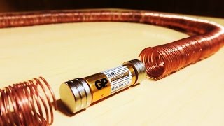
With only 4 components you can experiment with wireless transmission of electric energy. This system exploits the resonant inductive coupling between two coils to transmit energy between them.
Slider 2732 (you should check his channel, he has great experiments on wireless systems and other subjects / slider2732 ) makes the following suggestions:
Any NPN or PNP small signal transistor can be used. For PNP, simply swap the battery connections over. Best to try, include 2N2222A, S9014, C1815, C1213, MPSA06. For PNP, 2SA733 and upward.
For overheating troubles, make sure to have 12+ turns and/or add 100ohm resistor in series to a power wire input, or a similar resistor to the Base.
Adding a 1N4148 diode on the other power input will also drastically reduce heat and current.
To run at higher voltages than 1.5V, add a 5K variable resistor to the Base.
Use 12 turns and above for reliable operation, around 26AWG wire works best.
Small ceramic capacitors can be added to receiving coils for improved efficiency. 0.001 range ('102' as written on popular types). Receiving coils can be various and need not match the transmitting coil...such as a ferrite round choke with LED on top, 1/2 diameter coil or pancake coil.  Наука
Наука


If only this channel existed when i was studying engineering, i wouldn't have had to sit in boring classroom lectures with absolutely zero practical application examples.
Thank You for making these videos.
I tried this experiment at least 10 X before final success. drove me crazy... but now once it works, I can't stop making these things and they all work. Here are my tips... make sure you have a low voltage LED, not an infrared LED. the LED's I'm using are 2.5V or less. Make sure you use the proper transistor. make sure you remove the enamal from the magwire at the connection points. I also bought a battery holder box with leads coming out of it so i was sure the connections were being made. I also soldered my connections to the transistor. not twist tied, but soldered. IT WORKS!!! I've tried different quantity of winds and it works at different windings. Good Luck... and Thanks, Ludic Science...
+Jim H Glad you made it work! Happy 2016
+Ludic Science Ludic UR circuit is a bit trippy. You need a stabilising resistor and capacitor so that it will always work. Look at this www.seekic.com/circuit_diagram/Signal_Processing/Oscillator_Circuit/CENTER_TAPPED_TRANSFORMER_AUDIO_OSCILLATOR.html
(The transformer is replaced with the coils and the speaker is replaced with the Led, unless you want sound)
can i use transistor MPS2222A
t'ai un génie ludic science
Do you use insulated wire?
I am a Science and Math teacher and use your videos very often. Best we've seen!
Great educational videos. Keep them coming!
Bush Camping Tools
ssss
Thank you for an extremely clear, well-explained presentation!
I just made this, worked surprisingly well! Thanks for the clear instructions :D
I have used this video of yours for a science project in my university. It made a very useful central source. Thank you!!! Please keep your videos as such coming!!'
thanks
thanks a lottt "ludic science"!! helped me in my project very well
Hello from Greece. I made it successfully with a "tip 9014c" transistor. Thank you for the demonstration!!!
thanks for the input
WOW!!! I thought I knew a lot about electricity and electronics. This was very helpful for me and easy to understand. Thank you! :)
Works well. Thank you Ludic Science.
This video is very informative!!!
Please keep it up
This is a good video on transformer principles. The transistor oscillator is a good addition with a good explanation. It is good how at 3:14 you explain generator principles. Near the end, you say that the turns have to be the same. They don't necessarily have to be the same. Googling "turns ratio" will get you all the info on how to vary turns ratio. It might have been good to insert a piece of iron like a nail or something to show the effect of a core on this circuit.
emf4kv Thanks for your input
A great, fun and very creative video. I don’t at all understand the thumb downs! Great job. Keep creating!
will using less coils in the second loop affect the conclusions?
Thank you! A much needed basic presentation.
Great Man it works. I had made it today for my friend and your circuit helps me alot
Thanks for the tips you have discussed here.
Muy bueno. Hay que ampliarlo. Seguro nos va a ayudar. Excelente.
Brilliant. Thanks for this experiment. Well explained. Great videos.
Fadi Jabr Thank you very much!
Thank you so much for explaining
no sabia que también tenia el canal en ingles, me sorprende cada dia mas.
felicidades.
Vari Tech gracias!
Ive watched this video 15 times at least. Im finally gonna make one but i love the way this guy explains what hes doing. He sounds like pedro from Napoleon dynamite if anyone know that movie lol
VOTE FOR LUDIC !!!
Surprisingly simple!
Neat demo thanks!
Amazing tutorial, simplistic and accurate approach, and to the point in helping someone understand the fundamentals. Thank you sir! Keep up the good work.
DIGITALCANADA Glad you like it
Very Cool. Many Thanks!
Excellent innovative videos
Hi Ludic,
Make the transmiter coil as a joule thief - LED goes to transistor emiter- it will light up if you touch coil centre tap - or if you touch collector or touch transistor base with the other leg of the LED.
Lots of fun...LOL !
Great!
amazing explanation
Excellent work brother
Thanks
god its working !! thanks alot.. I used battary from multimeter !! :) Thank you professor
Thank you it is a simple and beautifull explanation.
Very good, thank you for posting
✌
Excellent project. Also I liked his English.
great explanation 👍
at the first time to try this for me in 2009 it became a great deal to connect a transistor!
Beautifully demonstrated and explained!Thank you!
Thank you so much for this video!
A small doubt though, is this project and tesla coil the same thing?
Help to the query would be greatly appreciated.
Thanks Ludic science.I did this for science exhibition and got first.
Lol
+Bradman175 lol at your lol!
N Gokul is it working on mutual induction ? Plz help
Really very nice and useful, great for kids too. Thank you very much. Fantastico!
Thanks :)
Thanks a million.... It really wotks
Great video, man!
thanks!
can you please give me the theory it is based on?? a url perhaps.. please
Hi ,thanks for your education. power to your elbow
Great project. What is the use of the transitor in the coil? is it used as an amplifier,a switch or a medium for AC? Please help me with it . A detailed explaination please. Thank you
explained in a simple way so simpletons like me unferstand how it works and how to replicate it.
Thank you.
I want to empower my distant circuit by providing atleast 5V for the microcontroller to work. Can you suggest the transistor or other modifications required for using a 9V battery as thee source in transmitting circuit??
You the MAN LUDIC !!!
Great video. I gave it a LIKE
Ludic Science This was quite helpful. Working with a BD139 transistor, how will i alter the other components to make it work? What is the voltage of the battery you were using as well? Or the number of turns in the coil.
Wireless electricity transfer . A simple video is very nice video.
cool video..can other transistors be used? If so, how do you identify the Base, Collector, Emitter for others besides 2n2222
This is identical to SWES 2 - which I created and showed on my channel, July 1st of last year. The original SWES dates from 2012, same but using a pancake coil.
So, a bit of help for people asking questions on this video:
Any NPN or PNP small signal transistor can be used. For PNP, simply swap the battery connections over. Best to try, include 2N2222A, S9014, C1815, C1213, MPSA06. For PNP, 2SA733 and upward.
For overheating troubles, make sure to have 12+ turns and/or add 100ohm resistor in series to a power wire input, or a similar resistor to the Base.
Adding a 1N4148 diode on the other power input will also drastically reduce heat and current.
To run at higher voltages than 1.5V, add a 5K variable resistor to the Base.
Use 12 turns and above for reliable operation, around 26AWG wire works best.
Small ceramic capacitors can be added to receiving coils for improved efficiency. 0.001 range ('102' as written on popular types). Receiving coils can be various and need not match the transmitting coil...such as a ferrite round choke with LED on top, 1/2 diameter coil or pancake coil.
The system is the simplest, not the best. The bare bones was my intention, for easy replication.
slider2732 May i quote your recommendations on the vid description?
Ludic Science Hi there...yes certainly, glad to help :)
sir can you tell another transistor that works the same.this one is not available
Great vid!!
+Wideband Records (wb-recs) thanks
how will you know which end has the negative and positive on the receiver part?
How do you calculate the emf induced in this experiment?
What is the turn ratio of the transmitting coil and the receiving coil?
And will doubling or increasing the receiver coil turns,increase the output voltage like in a transformer?
FYI for anybody that has had trouble making this work. I have found the 2N2222 pinout is NOT standardized. It varies between manufacturers, case styles, and part numbers.
Get an M-Tester = Transistor Tester = LCR-T4 is cool, cheap and useful. It shows you the pins
duckduckgo.com/?q=LCR-T4+&iar=images&iax=images&ia=images
ruclips.net/video/7Br3L1B80ow/видео.html
how to increase strenght of indcution for a lil.bit.long distance opration ?
& what if i increase the wire width ?
can you please explain why do we need centre tap, what is the purpose of it and how does the transistor connects and disconnects battery thousand time? can you use this configuration for an ac?
thank you.
I just wanted to tell you that i really like what you do. I'm studying engineer and physics in Paris and i would love to know how the small transistor can transforme the courant continue into an alternative one, Thank you so much
Can you tell me where the video is for the first scene in your channel trailer video?
Can more than one bottom coil be hooked up ? And still power the coil with the led over the other coils ?
also the led which u are using is of 3volts...but then how is it working with 1.5 V cell?
please reply asap...as i have made this for my school project and its not working...
Can i use regular wire that has insulation or does it have to be magnetic wire? Can i use 10 turns on the transmitting coil and 10 turns on receiving coil or both have to be 24 turns? How can the range be improve would less or more coil turns improve range?
Can we do that to charge cellphone? And if we can, please give us the schematics please?
I used the pn2222a, it worked but it was emitting less energy than yours. Will it make a difference if I use pn2222a or 2n2222a?
i didn't have a 2n2222 transistor instead of it i used bc548b is that why my bulb is not glowing bright i used 9v battery please respond i am newer to these electrical componets
i am not getting 2N2222 transistor . what transistow can i use instead of it .pllzzz tell me
Will there be a difference between pulsating DC and AC like in terms of efficiency or anything? How does a pulsating current work and how does a transistor convert it into a pulsating current?
How the no of turns of coil is decided any mathematical derivation available for that......also I wud like to know how much of inductance is good for these circuits as that can gv idea about turns?
These are a great educational video but i have a doubt in your wireless electricity 2 wich Cooper wire have been used??
Hi, epic experiment, can you please tell me sth, What makes the transistor turns on and off thousand times per second like you said in the video. Huhz
Mine doesnt work when i try to hover one coil above the other even though when we test each circuit separately, it works. Is there any reason why? :(
Brilliant!
Sir I am from India. Your videos are awesome
Thanks!
Can I use 2n2222a (TO-18 package) instead ?
Thats amazing
very useful!!
Hi, can you help teach the winding ratio for different wire gauge?
What could happened if we increased the number of turns in each coil (A AND B)? The brightness will increase or decrease?The range the LED can be turn will increase or decrease?
Please, could you give more info on how the transistor switches the coil current? Is the current in the coil is pulsing in one direction or is it changing directions?
82rah The transistor acts as an oscilator, the current in the coil does not change direction, it is pulsing in the same direction.
nice video ludic,
i read an article that the transmitter and receiver coil must have the same freq so it can resonant n the power can transmit. if we can't count the freq n want to further the distance, how we manage it with many loops of coil.
thanks. hoping your response
I will use my science experiments
i will try.
you explained it in a simple and clear way,,,thank u.can u please explain the circuit dig. the transistor and centre tap connection.
Hey man. I'm sorry I'm new to this concept, but could you please explain how a changing magnetic field is produced? I.e. how does the transistor connect and disconnect the battery without there being a capacitor or anything? How can it switch itself on and off?
Your help is very appreciated. Thank you for the video as well!
my wire is also a little less in diameter....the emmitter coil has 30 turns...and the reciever has around......could this be a problem???
Hi. I tried this and I want to ask you something regarding voltage of the circuit.
For my emitter coil, I wound the wire 5 times, made the center tap and wound the wire 5 more times.
For the receiver coil, I wound the wire 10 times.
I used a 1.5v AA battery and connected it to the emitting circuit, and connected a multimeter to the receiver circuit.
However, I got some bizarre readings, up to 8v.
Can I know why this is happening?
+DSK WhiteDwarf Follow the instructions in the video. The emitter coil is 12+12, not 5+5
Working with a BD139 transistor, how will i alter the other components to make it work? What is the voltage of the battery you were using as well? Or the number of turns in the coil.
Latifa Mbarak I have not tried with other transistors. The voltaje is that of an AA battery around 1.6 volts. The number of turns is given in the video.
will it work if the magnet wire is a bit thinner than the one you used and I used a bc 547 transistor.. will my circuit work?
yes you can use a bit thinner wire. as for the bc547, it should work
awesome..!!!
can you please explain the work of transistor in it?
oh! can we use any other transistor of the same type?
Im using the 2N3904 as a replacement of the 2222, im also using a size 20 wire. Im using an Apple 5v brick to power the primary coil, and on the secondary coil i have a 5v led. It's not working at all, any help.
Javier Portela The video states 1.5 volt (aa battery) to power the primary. More thatn 1.5 volts don't work.
Today I tried to put a 10k base resistor in place but the LED was barely lit. So I changed it back to 1k base resistor and that's working fine.
Hi, i need some help with this project, i have a everything, but i cannot tell if i have the correct type of transistor. would just any type work for this? I have a PN2222a6e transistor, possibly that would work?
-Thanks
Scotlahn Mccallister you can use 2N2222A, S9014, C1815, C1213, MPSA06
Can i know what may be the output voltage?
please reply asap.
and any other transistor can be used? if yes name its code.
thanks!😊👍
Great Video.What is the role of transistor here?
I can't tell if that wire is insulated already or not, is it just bare copper wire? or did you have to sand off the insulation on the points that you connected to the battery and transistor?
JamachGaming the wire is magnet wire, it is insulated. You have to sand off the insulation at the points of connection only.
can we use A.C source or
we should use only D.C source?