I worked at Arista Networks from 2013-2016 or so and was qualifying power supplies with basically the same form factor as this, possibly same interface but hard to tell since they cut the end off (probably to harvest the gold plating). The ones we had were made by Artesyn/Emerson and Delta, exact same power rating 495W (although we also had bigger ones up to 750W and higher I think) and same +12V and 12Vsb. There are probably just the two power outputs, some control GPIOs, an analog current sharing signal that connects to the other power supply, and a PMBus interface (which is basically built on SMBus which is similar to I2C). I believe these power supplies can be configured for automatic fan control, but you can also read the temp sensor and control the fan via PMBus, which is desirable because you don't want the PSU fan doing its own thing separate from the main chassis fans, otherwise you can end up with reversed air flow when one is pushing harder than the other.
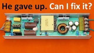
I really wanted to see you trying to power it. Seems in a very good shape, most of server PSUs that I got, were covered in dust so hard that I could barely read the components. This one seems brand new or used in a very well regulated environment.
0:15 80 Plus Platinum actually means it must be over 90% efficient :) (90% at 20% load, 94% at 50% load, 91% at 100% load). The specification: en.wikipedia.org/wiki/80_Plus
Well, that's a bit confusing :) but typically, they want to confuse the customer the other way. I'd expect a 90% efficient power supply to be called "95 Plus Diamond SuperMax Deluxe Pro" :D
@@DiodeGoneWild its just a legacy thing from the days when 80% efficiency was something special. Later they kept inventing more and more labels to accomodate the technological advancements. There used to be no gold or platinum :D
Nice supply. Packing lots of power in such a small size is quite an engineering achievement! I use a similar supply, albeit it's HP rather than Dell, as a central 12VDC supply for my lab.
nice video. its platinum rated power supply(92% efficient at half load) and server too not like dekstop like fan alone 2/3 of its volume, no wonder it bloody complex
Perhaps this arrangement is Flextronics' pet topology; I can't say I've seen it from any other manufacturer. Most other manufacturers would use the smaller inductor in an LLC resonant circuit (a few, such as the Seasonic G‑360, deliberately use a split‑bobbin transformer to get enough leakage inductance without needing a separate inductor) and not use the small 500V electrolytic capacitor.
These power supplies in Dell R620 like to blow up with a large blast. Something on the bottom goes up in smoke and shorts live to neutral killing circuit breakers. However output still works and the other power supply in the server keeps the server up & running :D
It could be a fixed frequency resonant topology. Usually they are frequency controlled, but this can also work with the variable input voltage... I think. I've read that the diodes across the possible resonant capacitors limit the power and prevent capacitive operation. I've never seen a setup like this before...
@@DuroLabs85you can keep tha max current rating as long as the output power is below maximum power the PSU is designed for For example i have modified a 300(real)Watt(12A rating on 12V line) PSU and it can deliver 24V@10A without problems. Just have to make sure the output diodes can take that much curren instead of trusting tha lable
Okay. But then overvolting the output how does the Supervisory IC does not interfere ? Its probably made to lock in at 12V right ? I have to revisit Great Scotts Video Again he did the PSU modification I think.
@@DuroLabs85 Well you should not go over the maximum total output power. My is 500W, I think original it was 12V 20A and the rest was the 5V and 3.3V, so now it's 20V and 20A that's 400W. I no longer use the 5 V and 3.3V, actually I completely removed all the components for the 5V and 3.3V. And about the supervisor IC you need to cut a trace on the PCB.
I think it might still work, just the card edge connector seems to have broke off when sliding it in the server or maybe servicing which may explain why it was in a such good condition from inside ??
I was also surprised it's so clean. It comes from a scrap yard. Maybe they broke the board off because they keep copper wires (or gold plated sections) separately.
@@DiodeGoneWildthese things are built like a tank. My guess is that it failed at one point and they broke off the connector to prevent it from getting back into the hot swap replacement bin as there are usually two of these in a single server.
My friend and I watched your Video and he suprised me when he showed me that he has the same power supply. I couldnt believe it. Great Video ad always! Please continue doing videos without tiktok garbage!
Very interesting to see all the different designs of switching power supplies. Seemed a little odd to use a boost converter in the second stage before the transformer. The most logical would be to use a buck converter for that (especially given the already high voltage coming from the PFC stage). Given the power and voltages, currents are not very large either (because that could otherwise be a reason to design like this - increase the voltage to not have to handle as much current and be able to use thiner wires, get less ripple current in the capacitors and such things). But for something that is only intended to output a set voltage, the regulation range isn't an issue.
I have an old server ATX power supply laying around here that has the ability for 2 different power plugs, where either of them can be disconnected without it affecting the output. Would something like that be interesting for the channel?
@@DuroLabs85 less stress on the internal components... Less heat... And if your utility doesn't measure actual power and just measures current and voltage (not phased) then it would be cheaper to run
Awesome video, Thanks for sharing! I wouldn't mind seeing you get your hands on a Hewlett Packard HSTNS-PL48-B, Specs are 100-120vac 7a/200-240vac 5a or 240vdc 4.5a In and 400vdc 2.4aMax out 550w or 960w depending on input volts. I plan to use it for charging batteries (solar setup). Unfortunately I have not been able to get it out of idle mode into standby mode as of yet.
I have 1 of those but for PC server so it has wires, it's a very good and stable 12V power supply, yes you can't play with the voltage but you can use buck\boost converters.
Can you make a video about double boost PSU? What is efficiency of each stage? What are the strong and weak points? Why don't we see such architecture in PCs?
But why not to use boost + buck converter then? After the buck state voltage will have less difference from the output, so efficiency will be higher due to lower conversion ratio. Or just use single SEPIC instead of boost+buck?
@@DiodeGoneWild buck can be made without a high driver, it's just a matter what side to consider high ;) Switch nMOS from the ground, but place capacitor and half bridge converter on +Vdd
I think if it was resonant, it would regulate the output voltage by frequency modulation (tuning closer to or further from resonance), and thus it would NOT need the second boost stage as a regulator. I'd have to open the transformer - if the windigs were loosely coupled, there's still some chance it is resonant, but I doubt it.
The schematic is rather simple, the thing is not built to last, not zero voltage switching. I wonder if there are any alternatives with higher rating (titanium).
It would be interesting to know , if there is a chance to modify this supply to 13.8V output. They produces harmonic free and RF clean output DC voltage suitable for powering radiostation etc. I have two pieces of 800W variant. They are working. How to start them is easy to find. But they give max 12.6V out.
Flextronics (FLEX) are superb PSU manufacturer. Top 1 for me. Just will say they made the excellent Corsair AX1200/1600i PSU. They are also contracted for most Apple chargers.
danyk a question, is it possible to calculate the temperature that a magnetic ballast of a fluorescent reaches in a situation of a stuck starter without doing it in practice, by the current in the circuit or by the mass of the ballast, I wanted to know the temperature that some of my ballasts would reach but without leaving them frying in practice
You can't without knowing how/where they are mounted. This value is seen in components as "W/K", i.e. how many watts will be radiated before the case goes one kelvin (=1 °C) up.
They typically say the abnormal temperature rise. There tend to be 3 or 4 thermal numbers on them. The first one is the winding rated temperature (for 100 000h life), most often "tw130" (130°C). The second number is the normal temperature rise, typically something from 20 (in super low loss ballasts) to 80 (°C). Then it might say the capacitive temperature rise (in a capacitive branch with a series capacitor in a lead/lag compensated pair), which is slightly higher than the normal temperature rise due to harmonics. For example 35c. And finally, the last number is the abnormal temperature rise. It can be anything from 50 to lets say 175 degrees, which bakes it in case of a stuck starter :). But keep in mind, that the abnormal temperature rise is measured also at 110% of the input voltage, so in reality it's not that bad. Some example of a low loss inductor marking: tw130 / 30 / 35c / 75. Some example from a crappy standard loss one, with no capacitive branch rating: tw 130 / 60 / 175. (60 is the normal t rise, 175 is the abnormal)
@@DiodeGoneWild I'm a bit surprised the higher-loss ballasts aren't required to have a thermal cut‑out in case the starter remains stuck (let's face it, most stores just leave a few lights in that state indefinitely); then again, peeking at some of the IEC standards has me disillusioned with them in general (impedance‑protected motors are also allowed quite a lot of leeway) so I don't expect that much…
The control circuitry looked more than a tv tcon...too packed and complicated. A psu you dont want to fail in your hands and have to repair with or without schematic, little difference would it make
Oh, and this is being used as a PFC Boost circuit. So typically input of (120-240v). At 240v I am 100% sure the boost stage is >97% effeciency. Talking 2.5 amps max to hit the power rating, this is a situation for a boost converter
Overengineered partial CRAP! I know there is a lot of safety stuff needed to not BLOW UP server MB, but really all of today's server PSU are INSANE!!!!!!!!!!! Just use some GaN's and a straight forward LLC or similar topology and you are done.
@@TheTallGirl I was referring to today's server PSU's. I used to maintain Dell servers, and none of them used Gan's yet, being a ten year on design. One INSANE thing about servers, that sellers LIE and LIE about is how long they last. A server can easily last 50 years, with maybe one time PSU change over due to caps not making it, and hard drive change overs. Where I worked, and because newer server were not much faster, we planned to keep using them for another 5-8 years, but were forced to change them because the EVIL EVIL M$ made it impossible to stay software compatible.


![Gucci Mane & Sexyy Red - You Don't Love Me [Official Music Video]](http://i.ytimg.com/vi/j7IBqyFKT4c/mqdefault.jpg)

I worked at Arista Networks from 2013-2016 or so and was qualifying power supplies with basically the same form factor as this, possibly same interface but hard to tell since they cut the end off (probably to harvest the gold plating). The ones we had were made by Artesyn/Emerson and Delta, exact same power rating 495W (although we also had bigger ones up to 750W and higher I think) and same +12V and 12Vsb. There are probably just the two power outputs, some control GPIOs, an analog current sharing signal that connects to the other power supply, and a PMBus interface (which is basically built on SMBus which is similar to I2C). I believe these power supplies can be configured for automatic fan control, but you can also read the temp sensor and control the fan via PMBus, which is desirable because you don't want the PSU fan doing its own thing separate from the main chassis fans, otherwise you can end up with reversed air flow when one is pushing harder than the other.
We'd snap off the connector from dead ones that were no longer in warranty. Prevents swapping a dead one for another dead one.
Even though he drew the schematic by hand, I have never seen anyone else draw such a good schematic. It's a great video, thank you.
I really wanted to see you trying to power it. Seems in a very good shape, most of server PSUs that I got, were covered in dust so hard that I could barely read the components. This one seems brand new or used in a very well regulated environment.
I barely understand anything about the electrical components but love watching it as always.
12:23 this cute creature is more intelligent than a lot of engineers i know.
0:15
80 Plus Platinum actually means it must be over 90% efficient :)
(90% at 20% load, 94% at 50% load, 91% at 100% load).
The specification: en.wikipedia.org/wiki/80_Plus
Well, that's a bit confusing :) but typically, they want to confuse the customer the other way. I'd expect a 90% efficient power supply to be called "95 Plus Diamond SuperMax Deluxe Pro" :D
I assumed it meant something to do with a beverage suggestion.
@@DiodeGoneWild its just a legacy thing from the days when 80% efficiency was something special. Later they kept inventing more and more labels to accomodate the technological advancements. There used to be no gold or platinum :D
Nice supply. Packing lots of power in such a small size is quite an engineering achievement! I use a similar supply, albeit it's HP rather than Dell, as a central 12VDC supply for my lab.
Nice schematic and explanations! Seeing some measurements and waveforms of this thing in operation would be nice.
nice video. its platinum rated power supply(92% efficient at half load) and server too not like dekstop like fan alone 2/3 of its volume, no wonder it bloody complex
12:06 did you notice your old power supply is the same brand? :) Both made by Flextronics
I work at the Flex factory
Perhaps this arrangement is Flextronics' pet topology; I can't say I've seen it from any other manufacturer.
Most other manufacturers would use the smaller inductor in an LLC resonant circuit (a few, such as the Seasonic G‑360, deliberately use a split‑bobbin transformer to get enough leakage inductance without needing a separate inductor) and not use the small 500V electrolytic capacitor.
What an awesome video. I have learned so much about switch mode PSUs and electronics because of you and your videos, thank you 😃😃😃
Hi, thanks for the video Diode!
These power supplies in Dell R620 like to blow up with a large blast. Something on the bottom goes up in smoke and shorts live to neutral killing circuit breakers. However output still works and the other power supply in the server keeps the server up & running :D
It could be a fixed frequency resonant topology. Usually they are frequency controlled, but this can also work with the variable input voltage... I think. I've read that the diodes across the possible resonant capacitors limit the power and prevent capacitive operation. I've never seen a setup like this before...
495 is an interesting number.
Maybe some regulation requires it to contain something extra (that increases the manufacturing cost) from 500W up?
Collocation charges... You can get billed on the number of height units typically 1U to 4U and how much power it can pull.
Lol... someone broke off the gold plated pcb connector
Great video thansk for the great explanation. I've not seen the double boost topology unti watching your video 👍
Very neat psu, so much control circuitry. Would love to find a full schematic and really figure it out.
Is it just me or the voice became somewhat worried/tired? Hope everything is okay.
I've caught some creature, maybe THAT creature again, but it went away in about 4 days.
@diodegonewild that's niiiiiice
I like your voice as well as the videos......
This one would be really hard to modify for a different output voltage, 2 years ago I modified 2 ATX PSU to go up to 20V!
does the current capability stays the same though ? I doubt that it probably reduced the current a bit to match the power output.
@@DuroLabs85you can keep tha max current rating as long as the output power is below maximum power the PSU is designed for
For example i have modified a 300(real)Watt(12A rating on 12V line) PSU and it can deliver 24V@10A without problems. Just have to make sure the output diodes can take that much curren instead of trusting tha lable
Okay. But then overvolting the output how does the Supervisory IC does not interfere ? Its probably made to lock in at 12V right ?
I have to revisit Great Scotts Video Again he did the PSU modification I think.
@@DuroLabs85 Well you should not go over the maximum total output power. My is 500W, I think original it was 12V 20A and the rest was the 5V and 3.3V, so now it's 20V and 20A that's 400W. I no longer use the 5 V and 3.3V, actually I completely removed all the components for the 5V and 3.3V. And about the supervisor IC you need to cut a trace on the PCB.
@@DuroLabs85 Just dont use PSUs where the supervisor is build in the PWM CTRL. IC. That can be foolde too but at that point just find different PSU
I think it might still work, just the card edge connector seems to have broke off when sliding it in the server or maybe servicing which may explain why it was in a such good condition from inside ??
I was also surprised it's so clean. It comes from a scrap yard. Maybe they broke the board off because they keep copper wires (or gold plated sections) separately.
@@DiodeGoneWildthese things are built like a tank. My guess is that it failed at one point and they broke off the connector to prevent it from getting back into the hot swap replacement bin as there are usually two of these in a single server.
@@xenoxaos1 Yess, I always try to find these in the Local Market here where they have like retired server gear.
500V electrolytic? That’s also something new!
Once I came across some giant 2200uF 500V capacitors, but otherwise just up to 450V.
Wow, they must' have been absolutely enormous! You certainly wouldn't want to get a shock off them. Instant death!
Good job 👍... greetings from Brazil..🇧🇷
My friend and I watched your Video and he suprised me when he showed me that he has the same power supply.
I couldnt believe it.
Great Video ad always! Please continue doing videos without tiktok garbage!
Very interesting to see all the different designs of switching power supplies. Seemed a little odd to use a boost converter in the second stage before the transformer. The most logical would be to use a buck converter for that (especially given the already high voltage coming from the PFC stage).
Given the power and voltages, currents are not very large either (because that could otherwise be a reason to design like this - increase the voltage to not have to handle as much current and be able to use thiner wires, get less ripple current in the capacitors and such things). But for something that is only intended to output a set voltage, the regulation range isn't an issue.
I have an old server ATX power supply laying around here that has the ability for 2 different power plugs, where either of them can be disconnected without it affecting the output. Would something like that be interesting for the channel?
damn the inside it's beautiful
Někdo byl asi nakupovat na burze ve Frenštátě pod Radhoštěm :D Jinak pěkné video.
Great work.
Great as always 🎉🎉🎉
Simply nice!!! Thank you.
FYI... The PFC can be disabled via software in the server control system
@@xenoxaos1 Ohh intresting, but why would they want to like disable the PFC ?
@@DuroLabs85 less stress on the internal components... Less heat... And if your utility doesn't measure actual power and just measures current and voltage (not phased) then it would be cheaper to run
@@xenoxaos1 Ohh that makes sense, Thank You :)
Then how is the boost circuit driven (since it needs to still boost the voltage in this design)?
Awesome video, Thanks for sharing!
I wouldn't mind seeing you get your hands on a Hewlett Packard HSTNS-PL48-B, Specs are 100-120vac 7a/200-240vac 5a or 240vdc 4.5a In and 400vdc 2.4aMax out 550w or 960w depending on input volts.
I plan to use it for charging batteries (solar setup).
Unfortunately I have not been able to get it out of idle mode into standby mode as of yet.
I have 1 of those but for PC server so it has wires, it's a very good and stable 12V power supply, yes you can't play with the voltage but you can use buck\boost converters.
Hey. What about making video about different SMPS designs in one video? And comparison of them? Would be longer video/series.
Can you make a video about double boost PSU? What is efficiency of each stage? What are the strong and weak points? Why don't we see such architecture in PCs?
Ďalšie skvelé video s reverse-engineeringom spínaného zdroja, paráda a mačička tiež vždy poteší 😀.
But why not to use boost + buck converter then? After the buck state voltage will have less difference from the output, so efficiency will be higher due to lower conversion ratio. Or just use single SEPIC instead of boost+buck?
I was also wondering about this, but I guess a boost regulator is easier as it doesn't require a floating gate drive.
@@DiodeGoneWild buck can be made without a high driver, it's just a matter what side to consider high ;) Switch nMOS from the ground, but place capacitor and half bridge converter on +Vdd
Wow! There seems to be alot of computing power to control this thing. Looks like it could be on par with a Beaglebone 😅
I guess that the output mosfets are load switches, as these psus usually are installed in couples for redundancy and they're hot-swap
Is there a possibility that it could be a resonant LLC converter topology after the PFC cicuit?
I think if it was resonant, it would regulate the output voltage by frequency modulation (tuning closer to or further from resonance), and thus it would NOT need the second boost stage as a regulator. I'd have to open the transformer - if the windigs were loosely coupled, there's still some chance it is resonant, but I doubt it.
The schematic is rather simple, the thing is not built to last, not zero voltage switching. I wonder if there are any alternatives with higher rating (titanium).
Awesome device
It would be interesting to know , if there is a chance to modify this supply to 13.8V output. They produces harmonic free and RF clean output DC voltage suitable for powering radiostation etc. I have two pieces of 800W variant. They are working. How to start them is easy to find. But they give max 12.6V out.
Flextronics (FLEX) are superb PSU manufacturer. Top 1 for me. Just will say they made the excellent Corsair AX1200/1600i PSU. They are also contracted for most Apple chargers.
That's a wied topology for a power supply. Where is the output? Is it broken?
Just managed to fix my PC that Windows updates messed up, and the first thing is a new video by DGW!
danyk a question, is it possible to calculate the temperature that a magnetic ballast of a fluorescent reaches in a situation of a stuck starter without doing it in practice, by the current in the circuit or by the mass of the ballast, I wanted to know the temperature that some of my ballasts would reach but without leaving them frying in practice
You can't without knowing how/where they are mounted.
This value is seen in components as "W/K", i.e. how many watts will be radiated before the case goes one kelvin (=1 °C) up.
Power consumption of a ballast in a short circuit can be calculated only if you have the induction value of it (H).
They typically say the abnormal temperature rise. There tend to be 3 or 4 thermal numbers on them. The first one is the winding rated temperature (for 100 000h life), most often "tw130" (130°C). The second number is the normal temperature rise, typically something from 20 (in super low loss ballasts) to 80 (°C). Then it might say the capacitive temperature rise (in a capacitive branch with a series capacitor in a lead/lag compensated pair), which is slightly higher than the normal temperature rise due to harmonics. For example 35c. And finally, the last number is the abnormal temperature rise. It can be anything from 50 to lets say 175 degrees, which bakes it in case of a stuck starter :). But keep in mind, that the abnormal temperature rise is measured also at 110% of the input voltage, so in reality it's not that bad. Some example of a low loss inductor marking: tw130 / 30 / 35c / 75. Some example from a crappy standard loss one, with no capacitive branch rating: tw 130 / 60 / 175. (60 is the normal t rise, 175 is the abnormal)
@@DiodeGoneWild I'm a bit surprised the higher-loss ballasts aren't required to have a thermal cut‑out in case the starter remains stuck (let's face it, most stores just leave a few lights in that state indefinitely); then again, peeking at some of the IEC standards has me disillusioned with them in general (impedance‑protected motors are also allowed quite a lot of leeway) so I don't expect that much…
ThanK you ❤❤
رائع
شكرا لك على الشرح القيم
honestly I think they only removed the gold plated contacts. Id try turning it on :D
Please next,pulse induction metal detector
Now try to get it to power on and test it!
There was nothing on the part of the PCB that is broken, just connections
look like interleaved PFC
Please power it and fix it if it can be fixed.
Properly made PSU safe and cheap.
Make drsstc plz
How can i donate some PSU for you? (Am from czech :) )
The control circuitry looked more than a tv tcon...too packed and complicated. A psu you dont want to fail in your hands and have to repair with or without schematic, little difference would it make
Sir can you please explain how to calculate numbers of truns of flyback transformer is there any simple calculation method
I recently took apart a broken ps4 (PlayStation 4) and took out the power supply and the motherboard. Im gonna use them as decor.
This PSU is complex and complicated. My level of electronics certainly is below this design.
Holy sh@t! Too bloody complicated and too cramped in there.
So let's take a look at iiitttt...
Boost converters have low efficiency, and have two of them is series and have >80% efficiency is interesting.
Boost converters can have fantastic effeciencies. Even low voltage boost converters can beat 90%.
Oh, and this is being used as a PFC Boost circuit. So typically input of (120-240v). At 240v I am 100% sure the boost stage is >97% effeciency. Talking 2.5 amps max to hit the power rating, this is a situation for a boost converter
@@Calandron1 interesting. I think 90% is possible only with a very little voltage difference
@@Calandron1 wow, in this PSU they use diodes, hard to believe in 97%
Overengineered partial CRAP! I know there is a lot of safety stuff needed to not BLOW UP server MB, but really all of today's server PSU are INSANE!!!!!!!!!!!
Just use some GaN's and a straight forward LLC or similar topology and you are done.
Yes, the complexity of something that just produces two voltages, is totally crazy ;)
That power supply is ancient. It is like saying, why they used vacuum tubes when you can just use transistors. There was no GaN's back then.
@@TheTallGirl I was referring to today's server PSU's.
I used to maintain Dell servers, and none of them used Gan's yet, being a ten year on design.
One INSANE thing about servers, that sellers LIE and LIE about is how long they last.
A server can easily last 50 years, with maybe one time PSU change over due to caps not making it, and hard drive change overs.
Where I worked, and because newer server were not much faster, we planned to keep using them for another 5-8 years, but were forced to change them because the EVIL EVIL M$ made it impossible to stay software compatible.
80 Plus Platinum 🫠
That Power supply might be bloody expensive 🤑🤑