Estimating an Antenna's Impedance at a Distance: Impedance Transformation in a Feedline (039)

HTML-код
- Опубликовано: 24 окт 2022
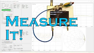
- In this video I will be showing you how to get an estimate of the impedance of antenna or other load at the other end of a feedline.
So, you have an antenna at the top of a tower. You know the length of feedline between it and you. You know the type of feedline and its velocity factor.
You measure the impedance at the end of the feedline you are at.
With this procedure, you can back-calculate the antenna's impedance without having to climb the tower.
I will present the *FUN* way and the EASY way.
Because this is non-ideal feedline, it will be a reasonably close estimate, but not the kind of spot-on precision you would get if you measured it right up close and personal like.
I strongly recommend that you use a nanoVNA, miniVNA tiny, high-end VNA or similar device to measure impedance. I have not had good experiences getting accurate impedance measurements using the average antenna analyzer.
==================================
TLW Settings used for the Easy Way
----------------------------------
Cable Type: RG-8A (Belden 8237)
Feet
Length: 76.167 feet
Frequency: 10 MHz
Source: * Normal
* Input
Resistance: 63.58
Reactance: -2.69
==========================
==== PROMISED LINKS ======
==========================
Downloadable, FREE Smith Chart
www.electronicproducts.com/sm...
TLW, Transmission Line Program for Windows, FREE downloadable ZIP file
www.arrl.org/files/file/QST%20Binaries/June2014/TLW3.zip
Time Markers for Your Convenience
----------------------------
00:05 Initial Comments & Introductions
01:45 The FUN way ...
01:56 What do I need to know?
03:12 What are we going to be doing?
03:18 The Test Load
03:39 The Feedline
03:57 Where is the Test Load?
04:04 Where are we measuring from?
04:11 Our final goal
04:23 Preparations
04:29 Calculate the Feedline's Electrical Length
05:12 Measure the Impedance at the End of the Feedline
05:35 The Smith Chart Itself
05:46 STEP 1: Prepare Feedline Wavelengths
06:25 STEP 2: Normalize the Measured Impedance
06:52 Plotting on the Smith Chart
07:41 Step A: Plot the Normalized Impedance
07:47 Step B: Draw the SWR Circle
07:57 Step C: Draw the Line Center to Edge through the Z
08:07 Step D: Note the Wavelength Value on the Edge
08:17 Step E: Moving Around the Smith Chart
08:52 Step F: Mark the New Wavelength Point
08:58 Step G: Draw a Line from the New Point to the Center
09:10 Step H: Note where this New Line Crosses the SWR Circle
09:15 Step I: Determine the Normalize Impedance Value at that Spot
09:32 Step J: Un-Normalize the Impedance
10:25 VNA Cal at the End of the Feedline, Measured Impedance
11:04 The *EASY* Way
11:38 The Results?
12:26 Final Comments and Toodle-Oots
-----------------------------


great information
Glad it was helpful!
I made up that random impedance in a small box as well , I used sma connectors like on the tinyVna, so we have two different values.
This is good for exercises , matching into an impedance at a specific frequency.
Cool! I used a N connector because I most often us my Tektronix VNA which sports N connectors. It is nice to have a "known bad load" for various testing scenarios.
You should see what you get measuring your "known bad load" with various off the shelf antenna analyzers. An interesting exercise. 🙂
yes the version i built and used after seeing your idea, had three pairs of SMA connectors, this allows me to have three frequencies for the bad load ,I then sweep the load so I use my tinyVNA to sweep the Unknown load from say 7mhz to 30 Mhz then select three different frequencies, noting the Z ohms and Xs at each frequency i can then use SimNec to calculate the required inductor and capacitor values for each freq. then insert these into the path to get the match into our unknown load.
i built another small box to go between the VNA and the unknown load, here we can put in the C and L values.
This unit is then good for testing analysers and the difference they give on measurements. I find the MFJ analysers the worst.
Also using this with Simsmith or Sim NEC to find the L and c network values for a given frequency. So we could put a marker on any part of the simsmith chart and make a load value to simulate the antenna.
I was going to get the Rigexpert Zoom , but the Tiny VNA does it , it just that its not so portable in the field , as laptop and cable required to measure stuff.
I used SMA connectors as i have loads of this type , i can send you some if you want to play for with these . for free just email me from QRZ page ( GW4LWD )
I just put up these images .into my drop box , follow the links to load them
www.dropbox.com/scl/fi/qcof5qvo6exwju10l5mme/Will-image.jpg?rlkey=mi7apw1c14tkk2ow7d59q6qja&dl=0
www.dropbox.com/scl/fi/gcnawk4cdizzw5ydnr5me/28mhz.jpg?rlkey=ccg45z82kn02k0l3ig9vwmii1&dl=0
www.dropbox.com/scl/fi/q2io8vwxm6evi9t3hdg01/series-L-and-C-unit.jpg?rlkey=b94c3z0hn56ehote9pemccjbz&dl=0
www.dropbox.com/scl/fi/q262letegqx7awv56kubh/tiny-and-unknown.jpg?rlkey=gp84zzhwo755qcfnwe9bwrwv2&dl=0
www.dropbox.com/scl/fi/1icton2m1boahn2uuw3et/dual-unknown-load.jpg?rlkey=5438ftnb5xmig3bn3ha5eqhwv&dl=0
www.dropbox.com/scl/fi/9z5bxoiyntk2f2fmd4mps/15Mhz.jpg?rlkey=9tzt37pmslosdurbphsgwkesr&dl=0
www.dropbox.com/scl/fi/p6wfcs31ifqjwqvd41j87/unknown-load.jpg?rlkey=9kvngdq6wurwrismr2k6e2w4e&dl=0
Here are some images
drive.google.com/file/d/15n9QB4EHS8dYb_CJi3Si01xRYpxcLrF9/view?usp=drivesdk
Also
drive.google.com/file/d/1VLunNUTmuW_aahJ6AhAymU9xJ1ybypVd/view?usp=drivesdk
The 10Mhz Smith chart
drive.google.com/file/d/1SiNOpGmpA0n6E38KVT7D9hNhT5sUfarE/view?usp=drivesdk
YT had relegated this to "Held for Review." I don't often check there (cuz it's *always* empty). Sounds like a neat idea.
This channel has to be one of the best resources for HAM's where is everyone? Is it possible to have a video summery on this series but tackling the same scenarios with open wire feedline?
For example. How would i calibrate the vna at the end of a length of 170ft of ladderline? Would i need a 1:1 balun at the shack end to convert the VNA to balanced and then another 1:1 Unbal at the feedpoint to convert it back to unbalanced for the calibration loads / stubs?
Many thanks.
Hmmmmm ... having never really worked with ladder line ...I'm going to have to do a little research on this.
Trying to figure out how any LC "L" or "T" network antenna Tuner could protect a Final output device from Antenna Swr reflected power effects using what Intuitively Should be a simple Bi-Directional impedance matching network that should Pass rf power (Forward or Reflected) equally Both directions easily passing any antenna Reflected power thru towards Rf final device.....Normally, only a transmission line "Isolator or Circulator" can effect 1 way Directional rf power continuity flow...What part of this video or transmission Line "Impedance transformation" enables a simple "LC" matching network to protect a rf final from antenna Reflected power ??
Do you have any tutorials about measuring the impedance of an efhw antenna with the help of nanovna? Or in general the impedance at the end of any wire?
The tuning of this antenna has to be done at the coaxial connector on the 9:1 BALUN which is part of the whole assembly. The nanoVNA (or any VNA or antenna analyzer) is looking to see a transmission line which, by their own definition, is two conductors. There must be a definitive return path.
Regarding the tuning of any single wire, you are not the first one to ask about that ... its velocity factor and, therefore, its electrical length is highly dependent on its physical surroundings. The simple use of insulated wire as opposed to bare wire for an antenna shortens the antenna because the presence of the insulation changes the velocity factor of the wire. You put it in the air as opposed to being near the ground or the building...different. This is why we cut purposely long, trim to tune in the orientation and environment that it will live in. 🙂
This is an amazing channel! I am not shure if you ever addressed what I'm going to ask, but I coudn't find it. My question is preety commom, and I'm not shure if its a myth or not. Does the lenght of coax between the rig and the antenna matters in terms of simple SWR to the radio? As one can use coax as an impedance transformer I'd think that yes, but is it just a constant SWR value along the coax even though the complex impedance is changing? In the end, does it matter or we should just use the minimum length to cut the losses? I'll be sure to write this down as too many experts seem to be divided on this one. Thanks in advance.
First of all, a big thank you for the encouragement!
You have a very good question! The answer is a decided yes and no. I know, this doesn't help much. But, let me explain. First the "no" and then the "yes" and then the "maybe."
No, it makes no difference. If we consider the coax to be lossless and look at the Smith chart, yes, the impedance continuously and cyclically morphs, repeating every electrical 1/2 wavelength. Throughout this 1/2 wavelength, the reflection coefficient and, thus, the SWR, remains constant. The components of the impedance change in such a way that the calculated SWR from the existing complex impedance at any given point is the same as it is at an other given point.
Yes, it does make a difference as viewed from the transmitter end of the coax. Coax is NOT lossless. If we consider a piece of coax which has a 1dB loss over its length at a given frequency, this means that a 100 Watt transmitter's power at the other end of the coax is about 79 Watts. If the antenna has an SWR of 1.6:1, it will be reflecting back around 4 watts of the 79 watts that it is getting from the coax. This reflected power travels back through the coax experiencing the same 1 dB of attenuation. Back at the transmitter end we get 3.2 watts coming back at us from the antenna; the remaining 0.8 watts is dissipated in heat in the coax. Comparing this to the 100 watts sent to the antenna, this *looks* to the transmitter like a 1.41:1 SWR. The signal loss in both directions fools us into thinking our SWR is better at the antenna than it really is.
One other factor ... the antenna itself. Some antennas are **really** weird about coax length and grounding and such (I know, I have one of those!). In that case, yes, the length, type, grounding, and just about anything else you might think of make some weird difference not covered by conventional theory.
So, like I said, yes...and no. Now that I have thoroughly muddied the waters, I hope that I've shed some light on the question at hand. 🙂
@@eie_for_you Ralph, first of all, let me thank you for the most complete and record-fast reply I've ever seen. Much appreciated. I truly love that most answers in the Ham Radio hobby are definitive "it depends"; it makes everything much more fun and approachable for the inquisitive experimenter. The Nano VNAs and Tiny SAs are amazing and only add to the fun and democratization of the craft.
You, sir, have indeed shed a lot of light on the question, and the "yes and no" answer is clearly the right answer. Many die for either the "yes" or the "no"; a true master knows it is neither. I'm a Brazilian Ham and Production Engineer and a true fan of yours, really honored by your reply. Thank you, 73 DE PP2PB (by the way, are you a Ham, sir?)
@@PBenettonWell, thank you very much! When we are dealing with the black magic world of R.F., it is often a lot of "it depends." The best we can do is know as much as can know and then learn more. None of us have the whole story perfectly!
Yes, I am a ham and have been since 1970 (WN2PUX, then). I am WA2PUX continuously licensed since 1970. 73! 🙂
Excellent! Just found (and subscribed) your channel. Thank you. Kevin M0XYM
Welcome aboard! Glad you liked the video!
Hi there , do you show how you made that test impedance load ?.
Actually ... no I never did. It is quite simple, though. I put a 33 Ohm carbon composition resistor in series with a coil of wire that I just threw together from some scrap. This across the connector. Then, in parallel with that combination, I threw a 27 pF ceramic capacitor. No calculations or goal apart from wanting something that was purposely non-ideal. I wish I could put a picture in here. Here is a link to a picture of the innards.
drive.google.com/file/d/10_aOotowIvmFgyKeHUh8Im4PcXFO55_C/view?usp=sharing
@@eie_for_you I’ve subscribed , interesting topics .
@@pcmultimedia1 Welcome to the "family!" 🙂
@@eie_for_you
Hi there , after thinking about your unknown load, I made up another version , but this one is completely variable.
It had a variable inductor, variable capacitor, and variable resistor, I can now create an unknown load anywhere on the smith chart , then use the VNA to read it and calculate the L/C to match to it.
@@pcmultimedia1 Wow! Getting better and better! 🙂