
- Видео 185
- Просмотров 612 288
Electronics for the Inquisitive Experimenter
США
Добавлен 27 дек 2019
This RUclips channel is intended for the "Inquisitive Experimenter" who is interested in Electronics. What do I mean by that? This is the person who want to dig a little deeper, who wants to understand what goes on behind the scenes, they 'WHY' behind things, but, at the same time, doesn't want to have to have a masters degree in engineering to understand. I try to answer questions and provide the hard to find information.
I divide my videos up into two groups:
The numbered videos (e.g. 001, 002 ...) are the more basic videos covering foundational stuff, but still at a somewhat deeper level than the average, mainstream contents you find on the Internet. When there is a series, a letter is appended to the number to keep them in order.
The lettered videos (e.g. 00a, 00b, 00c) are the more 'advanced' videos with more technical content. In these I assume basic knowledge of stuff. If there is a series, I append a number after the letter to keep them in order.
30 Foot / 9 meter Antenna Mast on the Cheap (074a)
In this video I will walk though how to build a 30 ft / 9 m antenna support for yourself using simple lumberyard lumber and hardware. I will also show you the modifications I made for my own version that I used at Moose Lake.
Not everyone has a place to support one or both ends of a wire antenna.
This problem is not foreign to the amateur radio operator. Back in the long past, they devised a way of creating their own 30 foot or 9 meter support using basic stuff from the lumberyard. It was 40 foot (12 meter) back then when they could get 22 foot lumber!
I found this design in a 1940 American Radio Relay League (A.R.R.L.) "The Radio Amateur's Handbook." It is what I used as a starting place to...
Просмотров: 2 358
Видео


Step Attenuator: The Math (073b)
Просмотров 43714 дней назад
In this video I will walk through the derivation of the equations that I used to design the step Attenuator that I presented in the last video. I have provided a go-along-with-the-video formula sheet in a PDF. Here is the LINK to this sheet if you are interested: drive.google.com/file/d/1rZQ15pvpPuTs8-oxJ2lnWlqSUyll_K5M/view?usp=sharing I show the major steps in this video. I will not work thro...
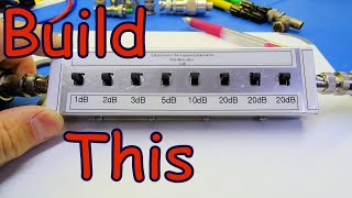
Step Attenuator Design, Build and Test (073a)
Просмотров 2,6 тыс.28 дней назад
CORRECTION That is 2^8 * 3 = 768 tests NOT (8! 1) * 3 = 120,963 tests. Either way, still too many tests to perform. POWER RATING Do not apply any more than 250 mW to this attenuator (A.C. or D.C.). That means no more than 3.5 VDC or 250 mW R.F. or any combination of A.C. and D.C. that amounts to 250 mW. In this video I will walk through the * Design * Build * Testing of an eight position Step A...

Creepage and Clearance (072)
Просмотров 722Месяц назад
This video is all about Creepage and Clearance, otherwise known at "Conductor Spacing," for electronic and electrical circuits which have higher operating voltages. We do not want arcs or conductive paths developed between conductors. To prevent this from happening, we need to have enough distance between conductors having voltage differences. NOTE: Yes, I know I have some overdriving on the au...

Galvanic Corrosion (071)
Просмотров 1,9 тыс.Месяц назад
Galvanic Corrosion is a problem that affects electronics, mechanics and a LOT more. In this video I will describe * What Galvanic Corrosion is * What you might see in troubleshooting because of it * How to prevent it. Get this right and you will save yourself a LOT of headaches. LINK to the Galvanic Corrosion Table drive.google.com/file/d/1ffz5mlMwCHX3sNRX4MrePqjSn-cJS1wj/view?usp=sharing Time ...

Measuring the Input Impedance of a Product, Circuit or System (070b)
Просмотров 2,4 тыс.2 месяца назад
There are two kinds of situations where you might want to measure the input impedance of a product, system or circuit: 1. At a Low frequency like an audio amplifier where there is no real concern about the complex aspects of impedance. 2. At Higher frequencies like a receiver pre-amp where we are very much interested in the complex impedance. I covered the first of these in the last video. If y...

Measuring the Input Impedance of a Product, Circuit or System (070a)
Просмотров 4 тыс.2 месяца назад
There are two kinds of situations where you might want to measure the input impedance of a product, system or circuit: 1. At a Low frequency like an audio amplifier where there is no real concern about the complex aspects of impedance. 2. At Higher frequencies like a receiver pre-amp where we are very much interested in the complex impedance. In this video I will be addressing the first of the ...

Single Sideband: Where do those extra harmonics come from? (036b)
Просмотров 4,2 тыс.3 месяца назад
This video is in direct response to a questions about where the extra harmonics came from as seen in the original video on Single Sideband. Se the link, below, to the original video. I will show what the ideal Amplitude Modulated signal SHOULD look like. I will then explain why the spectrum we saw in the original video did NOT look like this. LINKS for You LINK to the Single Sideband Video (036...

Impedance, Reflection Coefficient, Return Loss and VSWR (SWR) (069)
Просмотров 2,2 тыс.3 месяца назад
This video is in direct response to a request to create a video which talks about the relationship between Impedance and SWR. I will define and discuss both Impedance and VSWR (also known as SWR). However, in order to get a complete picture of the whole, I need to include their cousins, Reflection Coefficient and Return Loss. I will build from the foundation of an understanding of Impedance thr...
CASCODE Amplifier (Pt 3): Designing in a Fixed Gain (066g3)
Просмотров 7144 месяца назад
BJT Circuit Analysis: The CASCODE Amplifier (Pt 3) - Designed in Gain (066g3) This is the third video in this series on the CASCODE Amplifier. In the first video, I explained the WHY behind the CASCODE configuration and the HOW it works behind its operation. Here is a LINK to that video if you missed it: ruclips.net/video/j3r0-3vYkO4/видео.html In the last video, I showed you how to design one....
BJT Circuit Analysis: The CASCODE Amplifier (Pt 2) - DESIGN (066g2)
Просмотров 1,2 тыс.4 месяца назад
In the last video, I explained the WHY behind the CASCODE configuration and the HOW it works behind its operation. Here is a LINK to that video if you missed it: ruclips.net/video/j3r0-3vYkO4/видео.html In this video I will be showing you how to design one. I will walk through the entire design process including all of the assumptions, rules of thumb and engineering estimates needed to make thi...
BJT Circuit Analysis: The CASCODE Amplifier (Pt 1) (066g1)
Просмотров 4,1 тыс.5 месяцев назад
Here is yet another configuration of bipolar junction transistors called the CASCODE Amplifier. It has its roots in the 1930s and was originally created with triode vacuum tubes to extend the high-end frequency response of video amplifiers. This is the introductory video explaining the WHY behind this configuration and the HOW it works behind its operation. In the next video I wil be showing yo...
What is Early Voltage? (066f)
Просмотров 2,5 тыс.6 месяцев назад
Maybe you have heard of this whole Early Voltage business and maybe you haven't. It has all to do with the bipolar junction transistor and invades certain aspects of circuit analysis. In this video I will tell you all about the Early Effect and how it relates to the Early Voltage. I will also tell you how it relates to circuit analysis. To answer the request for a means of calculating the value...
nanoVNA: Measuring the Frequency Response of an Amplifier Filter (068e)
Просмотров 2,9 тыс.6 месяцев назад
In this video I will be showing you how to use your nanoVNA in stand alone mode to measure the frequency response of a VHF receive preamplifier that exists in my amplifier add on. Included in this video are * Set up the nanoVNA for a frequency response (through) measurement on an active device * Proper VNA calibration * Make the measurement results more readable by changing the REFERENCE POSITI...
nanoVNA: Measuring the Frequency Response of a Filter (068d)
Просмотров 4,3 тыс.6 месяцев назад
In this video I will be showing you how to use your nanoVNA in stand alone mode to measure the frequency response of what was supposed to be a 50 MHz bandpass filter that I threw together. This filter was supposed to have a 50 MHz pass frequency. I discovered that one (or more) of the unmarked components were not the value I expected them to be, so the reality of this filter is somewhat differe...
nanoVNA: Measuring the Input Impedance of a Filter (068c)
Просмотров 4,2 тыс.7 месяцев назад
nanoVNA: Measuring the Input Impedance of a Filter (068c)
nanoVNA: Measuring the SWR of an Antenna (068b)
Просмотров 2,5 тыс.7 месяцев назад
nanoVNA: Measuring the SWR of an Antenna (068b)
nanoVNA: A Practical Menu Walk Through (068a)
Просмотров 3,8 тыс.8 месяцев назад
nanoVNA: A Practical Menu Walk Through (068a)
Load Line Analysis: Answers to Two Poignant Questions (066e4)
Просмотров 5238 месяцев назад
Load Line Analysis: Answers to Two Poignant Questions (066e4)
Load Line Analysis: Example #2 - A Beta Stabilized Common-Emitter Circuit (066e3)
Просмотров 6528 месяцев назад
Load Line Analysis: Example #2 - A Beta Stabilized Common-Emitter Circuit (066e3)
Load Line Analysis: Example #1 - A Simple Common-Emitter Circuit (066e2)
Просмотров 1,3 тыс.8 месяцев назад
Load Line Analysis: Example #1 - A Simple Common-Emitter Circuit (066e2)
Load Line Analysis: Foundations - What is what and How is that? (066e1)
Просмотров 8718 месяцев назад
Load Line Analysis: Foundations - What is what and How is that? (066e1)
Three Ways to Measure the Output Impedance of a Circuit or Device (066d2)
Просмотров 6 тыс.9 месяцев назад
Three Ways to Measure the Output Impedance of a Circuit or Device (066d2)
A Multi-Transistor Example Circuit Analysis & Design (066d1)
Просмотров 1,7 тыс.9 месяцев назад
A Multi-Transistor Example Circuit Analysis & Design (066d1)
A Beta-Stabilized, Common-Emitter BJT Circuit (Pt1): Analysis and Design (066c1)
Просмотров 94210 месяцев назад
A Beta-Stabilized, Common-Emitter BJT Circuit (Pt1): Analysis and Design (066c1)
A Beta-Stabilized, C-E BJT Circuit (Pt2): Part Select, Rev Engineer, Bench Results (066c2)
Просмотров 55410 месяцев назад
A Beta-Stabilized, C-E BJT Circuit (Pt2): Part Select, Rev Engineer, Bench Results (066c2)
Establishing Realistic Expectations for Circuit Analysis & Design (067)
Просмотров 64510 месяцев назад
Establishing Realistic Expectations for Circuit Analysis & Design (067)
Basic Bipolar Junction Transistor Analysis: The Common-Base Circuit (066b4)
Просмотров 82910 месяцев назад
Basic Bipolar Junction Transistor Analysis: The Common-Base Circuit (066b4)
Basic Bipolar Junction Transistor Analysis: The Common-Collector Circuit (066b3)
Просмотров 1,8 тыс.10 месяцев назад
Basic Bipolar Junction Transistor Analysis: The Common-Collector Circuit (066b3)
Basic Bipolar Junction Transistor Analysis: The Common-Emitter Circuit (066b2)
Просмотров 1,5 тыс.10 месяцев назад
Basic Bipolar Junction Transistor Analysis: The Common-Emitter Circuit (066b2)
I use a old 4.5 metre aluminium ladder, fixed to a old railway carriage . I then use 2 alloy pole that fit inside each other with a 1m overlap with a small plastic 2" pipe at the top this gives me about 9m .lean it against the fixed in place ladder , then push it up about half way rope and fix pole to ladder. This gives me about 40 feet (12m). I think my idea came from the same design you described from a old ARRL antenna book ?
"You are a good antenna. I trust you. You did a good job in catching those small signals amidst that sea of noise. I wish more antennas were as good as you are. Not a sign of rust, all your dBs look like new. Keep doing what you do, I need an antenna like you."
I've been wondering and pondering that particular tower for about 30 years! It's nice to finally see someone use it. I have a 1955 HB and copied the simple dipole fed with 300 ohm open wire twin lead as my main antenna. Other than having to untwist it a cut some small pieces of pvc pipe to replace the broken spreaders, it's really good! Even snow and ice doesn't mess with it too bad, and it's gone off of the wires in a day anyway. The twin lead is ties with bits of broken wire, scrap plywood pieces to space it away from my barn. It's SO LOW, that when I split fire wood, I've hit it with the axe and hadnto hook it back up! Got to listen to the radio while splitting wood! I might win W2UD's "ugliest antenna award" contest! The twin lead open wire line goes right under my window and the two wires hook directly to the matching unit! NO COAX!!! Too broke, too unemployed! I can almost reach and touch the ends of my dipole which are less than 15 feet off the ground. The feed point is under 40 feet off the ground. I've NEVER had an antenna even close to 1/2 wave off the ground, except for two meters, which I have not operated two meters since I moved to Maine 14 years ago. I've been able to work 80-10 meters without any aparent disadvantages over the other 100 watt stations on the air. One thing about Maine is we're the closest to Europe and Africa and MOST antennas in the U.S. are already pointing my direction, which is a noticeable difference from when I spent 17 years operating my station in SC. , even with a beam up 45 feet. I always buy the cheapest 3/16' POLYESTER rope Wal-Mart sells in a 50 foot piece in a bag. NOT (NOT NOT POLYPROPYLENE!! Which is only good for water skiing. Nylon is EXCELLENT rope, but it stretches a LOT, which is good. Anyway long story short, if it's wrong (with antennas, that is,) I've done it! Thanks and Merry Christmas to you and thanks a lot for all you do.
That's something! The problem with the average rope is stretching and degradation due to ultraviolet light. Eons ago I used the real heavy gauge, galvanized steel electric fence wire (like 12 AWG). A regular, real tower ... not such a good idea. You will see why when my next video comes out. 🙂
@@eie_for_you Polyester and nylon are sunlight resistant, especially polyester. (those pants from the '70's will never break down!) On another note, I did knowingly make some contacts while my antenna was on the ground after an ice storm and it performed rather well! Of course a matching unit was involved. They should have a contest like field day where the whole point is to have the most dysfunctional antenna that can still make contacts. Can be a lot of fun and teach about antenna physics (physics is phun)! Take care!
The funny thing is, I bought a 500 ft roll that's been unopened in my attic since 2012! The open wire works so well, I haven't bothered to replace it. Lil' Abner would be proud of my ant. :) 73!
0:30 Hi Ralph !!
Great video, Ralph! I along with the help of my Elmer (a mentor in ham radio parlance for those who do not know what an Elmer is) built something very similar back when I was a Novice in the late 70s. The old ways are the best ways.
Sometimes that is sooo true! 🙂
I made one of these years ago but for CB. It works, but I suggest clamping the splice with u bolts to avoid weakening the lumber with a thru hole.
I can see your point, especially when made with 2x2s. I made mine with 2x4s, so that didn't end up being an issue for me. 🙂
Yep. The drawing is straight out of ARRL publications from the 1970's. I built a couple of 'em back in the day.
It sure is. My first exposure to it was with a 1940 handbook! 😲
If you use something like Dacron synthetic cord for the guy's you don't have to worry about "non-resonant" length, it's not metallic. I haven't used metal guy wires in years. Modern synthetic cord is amazingly strong, stronger than steel if appropriately sized. Even my towers are supported with commercial guy rope (Phillystran) and approved dead ends.
Suggestion: When using synthetic guy rope, use four to six foot of metal guy at the ground anchor point. It eliminates problems that one could have with chewing animals, minor grass fires, and string trimmer accidents.
I've never used anything but wire rope or metal wire for guy wires. I'm still a wire rope kinda guy (pun intended). For something like this with as many guys as it has on it, we are not talking very big stuff, for sure. Interesting thought about this synthetic stuff. 🙂
@@eie_for_you A friend who is a commercial tower climber introduced me to synthetic line. Apparently that's what they use on a lot of commercial broadcast tower installations these days. Ever since then that's what I have used for tower installations. The end is terminated just like a commercial wire rope would be, a eyelet type "dead end". Think of a piece of wire rope folded over to form a eyelet and then each end is twisted around like a barber pole. The inside diameter of that twisted barber pole is coated with a grit material. It is wrapped around the synthetic rope end (actually the same thing has been used with wire rope guy lines for a few decades) and that's it, no clamps needed.
@@mikesradiorepair Cool! 🙂
This a great idea you have resurrected from arrl. I wonder if a vertical wire run along the upper part would work too?
Interesting design. Thanks for posting. As a new ham back in 1998(?), I'd thumb through some of these older antenna books at ham fests. Often, I'd find something that piqued my interest. There are a plethora of classic wire antenna and support structure designs. Still have a decent copy from the mid 1970s which hasn't completely disintegrated. I tell the new hams to pick up mint copies if they come across one. They can be had for $3 - $10 plus they're a wealth of knowledge. Many variations of the end fed long wire designs which have been all the rage for the past decade or so, have all been around for almost a century now. Never would have ventured into using twin lead or ladder line designs without one of these older books. Merry Christmas and 73 de N2TEE
Merry Christmas to you and yours, too! 73 🙂
Looks perfect for a horizontal loop!
Is there a way to configure the NanoVNA with a computer program instead of via the tiny touchscreen?
There sure is! You can find the download links here: nanorfe.com/nanovna-v2-software.html The basic capabilities of the nanoVNA remain the same, there is some degree of expansion to how they are used with these programs and the user interface is entirely different. Merry Christmas! 🙂
@@eie_for_you Thanks!
Nice wooded antenna mast. Well thought out, and the build explanation is very clear. Thanks. Vic de KE8JWE
Thanks Vic! 73 and Merry Christmas to you and yours! 🙂
Nice video. Hey, how did you build your test board? did you etch it or did you use a CNC to remove the copper?
I very carefully placed electrical tape where the trace and any other copper needed to be, leaving all the rest exposed. I then etched it using Ammonium Persulfate. NOTE: This stuff likes to be *real* warm in order to work. I had to have my etching container on a heating pad (for my back) turned up to high to make it work. 🙂
Thank you for this simple and effective solution ❤
You are very welcome! 🙂
Isn't wider bandwidth good?
It depends entirely on what you are trying to do, actually. Like receiving CW (Morse Code), you want a very narrow bandwidth so that adjacent signals do not interfere with what you are trying to receive. On the other hand, listening to an A.M. signal, you want much wider bandwidth because the signal is wider. Notice, too, that the difference is the height of the resonance, not the width of the base. 🙂
Your example at 12:05 is actually more easily solved in one step by equating the parallel R with the desired total impedance by using the formula 4k*R/(R+4k) = 3K or simply R = 12k. Where 4k is the exiting resistor and 3k is the desired parallel (equivalent) resistance. No need for messy division.
Yes, I most likely would have done it the same way you describe in you comment for this simple example. But this would not have demonstrated the whole conductances in parallel simply add together. This principle is really important when dealing with complex impedances. 🙂
The formulas at 9:16 differ from what I got namely: Rp = Rs/(Rs^2 + Xs^2) and Xp = - Xs/(Rs^2 + Xs^2). The first one is the reciprocal of what you got and the second one the negative reciprocal.
The one thing that folks forget to include is the 'j'. Z=R+Xj and j*j=-1. If you do not include this in your calculations, then ... 🙂
@@eie_for_you The reason your formulas at 9:16 and 9:31 are wrong is very simple. It is known that the parallel combination of two impedances are ALWAYS less than the smaller of the two. According to your formulas the parallel resistance is GREATER than the series resistance and the parallel reactance is GREATER than the series reactance. This is not possible.
@@Jnglfvr I am now sitting here looking at my A.R.R.L. Handbook for Radio Communication, 2008 edition, page 4.45. Here on this page you will see in formulas (102) and (103) the exact same formulas that you see on the screen on my video at 9:16 and 9:31. Remember, these are used to convert the Series R+jX circuit into its parallel equivalent circuit. They are not the equations used to calculate the resulting impedance of two impedances in parallel. I hope this helps to clear this up. 🙂
@ well then I’m not sure what is meant by “equivalent parallel impedance” do you? If the impedances are different then so are the currents. So in what way, exactly, are they “equivalent?”
@@Jnglfvr If I have an impedance of, say, 3 + j8, this implies a 3 ohm resistance in series with an inductor whose reactance is 8 Ohms at a particular frequency. So, what if I want to represent this same impedance in terms of a resistance in parallel with some reactive component instead. The overall impedance would be the same. It just happens to be made up of two parallel entities instead of two series entities. These equations allow you to calculate the values of these new entities. Hope this helps. 🙂
Thank you but this is far too technical for beginnings. I can see from the comments its a good video for more advanced techies.
The point of all of my videos is not just the "how to" but the "why" behind it all. I appreciate your point of view on this ... and, yes, I can see your point. However, the point of my channel is for those who want to know more, understand the why, be able to extrapolate past the "how-to" to their own application. This requires more information which I provide. 🙂
@ You certainly do 😀
@@russc788 Thanks! 🙂
What a high level lesson! Congratulations sir, and thank you very much for your effort on helping us to understand complex concepts in a more simple way!
I am so very glad that this was so helpful. Thank you for letting me know! 🙂
What do you estimate the maximum input wattage to be? For instance, from a Ham Radio? Thanks.
I would not apply any more than 250 mW to the input either AC (e.g. RF) or D.C.(3.5 V) 🙂
👍Thank you sir.
You are welcome! 🙂
Outstanding exposition. Wish I had seen this before all the other confusing videos on the topic.
Thanks, man! I'm glad this was a help! 🙂
Thank you for a fantastic video about the RF Explorer.
You are very welcome! 🙂
so where do you find the "cheap" analyzer loads? Everything I look for is for the NanoVNA
There is nothing special about the loads for the nanoVNA except the connector (SMA). I'm assuming that you are wanting something other than SMA connector. The trick is NOT to look for "calibration standards" but to look for 50 Ohm R.F. terminations. Be mindful of the "accuracy" or they might specify this in terms of maximum SWR. Inexpensive ones will run about $30'ish. Good one's a lot more. On the other hand ... you could build your own if you are not to concerned with absolute precision. You can put 2 x 100 Ohm or 4 x 200 Ohm, 0.1%, size 1206, surface mount resistors in parallel. Then very carefully solder them into a connector being very, very careful to keep the lead lengths as short and massive as possible. Not great, but adequate for a number of applications. Hope this helps. 🙂
Thanks this was both great and entertaining.
Thanks! And it was fun to do, too! 🙂
Hi Ralph, Is there anything special about the open and short standards, can one just modify a connector with a short and call it good. What about the open standard can the same type of connector used for the short standard be used, but without the short installed?
Really good question! The big difference between very expensive, lab quality shorts and opens and the kind that are "good enough" for our use is certain aspects of construction and calibration (measurements of delays and the like). For what we do, you can take a connector, remove its center pin and you have an open "standard." The short standard is a bit more of a challenge. I used braid (coax shield or pieces of solderwick) to make the most massive short between the center pin and the body of the connector that I could possibly make. For what the average guy does, this would work just fine. Hope this helps. 🙂
@@eie_for_you Ralph, Yes its does thanks for the explanation I do have the SMA standards for the VNA, but no N-type or PL type standards. Looking on Ebay and other places the price of lab quality standards can get pricey so making my own is my best option as of right now.
@@U812-k7j Yeah, lab quality standards are ridiculous. You could use your nanoVNA using a port extension to evaluate your resulting standards. Cal with the SMA standards, add adapters to bring you to where you can connect your homemade standards, do the port extension, then connect your standards and see how they look. As a note ... in the professional R.F. world, the SO-239 is referred to as a "UHF female" and the PL-259 is referred to as a "UHF male." Knowing this will help you find stuff on the more professional sites. 🙂
💐💐💐
🙂
Awesome presentation sir! Impedance in a complex subject. Thanks for all you've done this year and may God bless you and your family in this holiday season! 73-W1RMD
Thank you so much, man! May God bless you and your family as well. 🙂
Good job at the derivation and explanation, your channel is one of the very few that combines the detailed math along with the electronics and hardware! Just curious, I wonder if instead of using the Ro||Rp=(Rp*Ro)/(Rp + Ro) resistors in parallel equation form, instead use the 1/(Ro||Rp) = 1/Ro + 1/Rp form of the equation, would this be easier or more complicated?
Thanks! 🙂 As far as using the alternate form of Ro||Rp ... me, personally, it seems it might complicate it. The only way to find out is to try it out and see where it leads you. 🙂
@@eie_for_you Yes, I may actually sub it in and try it just for giggles and a new challenge. But yeah having all of those reciprocal terms all over the place will most likely make it a complete mess :)
@@BowlingSuperior Let me know how it works out. 🙂
@@eie_for_you Just tried it, first step is the Rp||Ro, this is 1/((1/Rp) + (1/Ro)), which is 1/(Ro+Rp)/(Ro*Rp), which is (Ro*Rp)/(Ro+Rp) which is just the same equation that you started with. So, yes your method was indeed the best one to start with, sweet!
@@BowlingSuperior ☺☺☺Sweet! Thanks for getting back to me! 🙂
Ralph, do you have an opinion on the effectiveness of using the LDG RU-1:1 Unun for a common-mode choke you could share, please?
Well, I have never used one of these. They are supposed to be for this purpose. Advertised effectiveness and actual effectiveness can be two different things, but not always. I would say to test it for yourself to determine if they do the job. 🙂
Very helpful - Very COoL. My antenna went fully erect. Don't tell my GF. Just saying Thank you for the video. You RoCk. Cheers from So.Ca.USA 3rd house on the left
Excellent, thank you for this, thoroughly enjoyed watching the video! What is the maximum RF power handling capability of this system? Also, can I ask what was the power of the RF signal you used for testing?
Thank you! Testing-wise, I used the default output of my VNA, 0 dBm, 1 mW. As far as maximum power handling, I'd keep it at 250 mW, 24 dBm or less. By the way, I did a quick test to 1 GHz ... it kept reasonably decent SWRs up to 800 MHz! 🙂
@eie_for_you Thank you, the reason I asked about power used for testing is that I've heard SWR measurments can, to some extent, be influenced by incident power (i.e. if the power is low and there are losses when/if the signal is reflected, the SWR will appear low). However, I don't have much practical experience, only what I read in books or saw on RUclips. So not questioning anything, just trying to get a complete picture.
@@Alex-M0OOV Gotcha! I'm not sure that incident power has any significant effect. Impedance is impedance is impedance irrespective of the power applied to it. However, impedance can change with incident power as elements heat with increased power. This might be what they are referring to(?) 🙂
@@eie_for_you I'm referring to losses in the 'transmission line'. If these losses they are high, they could be misleading and result in a low SWR (this appears to be the case for very long and lossy coax). I'm wondering if low incident power in any system can also mislead and pose a risk of showing low SWR.
@@Alex-M0OOV You are right about losses in the transmission line making the SWR at the end of the transmission line appearing lower than they really are. This effect is accentuated as you go up in frequency as the losses are greater. This is why we calibrate the measurement instrument we use to measure the SWR of the attenuator at the *end* of the transmission line where the unit to be tested will connect. This way, all of the effects of the transmission line are taken into consideration in the measurement. The only thing that shows up in the actual measurement is the unit we are testing. 🙂
Professor Ralph, it would be a great help if you could help us graphically understand parameters B and G from parameters Y or Z already located on the Smith chart.
B & G are susceptance and conductance associated with admittance. Admittance is the reciprocal of impedance. I explain this in my video on "Impedance Basics" (ruclips.net/video/48RNn5tXw2g/видео.html). As far as how they relate to the Smith Chart ... once you have converted your impedances to admittances, you operate the same as you do with impedances except capacitive susceptance is positive and inductive susceptance is negative. As far as a video on the subject ... it might be a little while, but I will add it to the requested videos queue. 🙂
Saludos profesor Ralph, I see you from Cuba.
Hola! Glad to be seen! 🙂
It's amazing seeing these crash course videos after spending 2 years in ac theory lol. You are doing great here.
Thank you so much for the encouragement! 🙂
Great video. Thank you!
Thanks so much and you are very welcome! 🙂
Excellent demonstration
Thank you! 🙂
Can a vna check the condition of a coxal line without the antenna attached
It can be part of the overall evaluation and you do not need it to be connected to an antenna to do it. I have several videos on the subject of evaluating coax. Each of these evaluate certain aspects of a length of coax which can be compared to the datasheet for the coax to see how healthy it is. There is one on determining its characteristic impedance (ruclips.net/video/SSadMuMTlpo/видео.html), measuring its velocity factor (ruclips.net/video/dBtof6nRDj4/видео.html) and a whole series on testing coax - this is the first video in that series (ruclips.net/video/oLMdYBEnnD0/видео.html). I have a "COAX" playlist, too (ruclips.net/p/PL27hd2cDvPRs3_UpTHXF10AUM_KxeBTCn). I am hoping that this will help you. 🙂
@eie_for_you this will be of great help, I look forward to your channel.
Cool. My daughters 13 and 16 have a Tiny SA ultra, but they are getting a Siglent for christmas. Going to try and use this series for them to experiment with it.
WOW! Now that is **COOL**! 🙂
Excellent explanation!
Thank you so much! 🙂
Very helpful, thanks for your video
You are very welcome, my friend! 🙂
Correct concepts explained very well. Incredibly nice and engaging with your way of presenting and explaining. You deserve much much more viewers Suggested to my student. 73s
Thank you so much for the encouragement!🙂
Hi Ralph, today I was trying to measure impedance of PCB track. With the help of ufl connectors I connected one end of track to port1 and other end to port2. I wanted to measure impedance at different frequence (836.5mhz , 897.5mhz, 1950 mhz etc..). As per supplier of PCB its a 50 ohm track . In VNA I used smith chart to get the readings. Again the VNA has smith chart for S11 and S21. Which smith chart should I consider ( though FYI i was getting readings closer to 50 ohm for S11 smith chart)?.... Thanks
I had to think on this for a moment or two. This is no different than measuring the characteristic impedance of a piece of coax or other transmission line. If you are looking for simple impedance, then this video would help: ruclips.net/video/SSadMuMTlpo/видео.html But it seems you are looking for complex impedance. First, measuring impedance is always S11. Second, you calibrated the VNA at the end of the port 1 cable (I am assuming) so you need to terminate the other end of the trace with your 50 Ohm termination, not port 2. The effects of the cable and so on looking into port 2 will truly mess up the readings. If you calibrated the VNA at the connector on the VNA you will have to do a "port extension" to move the reference plane for the measurement to the end of the cable right where you are connected to your trace. Note, however, *any* divergence from a 50 Ohm system when doing the port extension will render the port extension useless. See this video where I show how to do a port extension: ruclips.net/video/Pti8Erw_Kkg/видео.html I hope this helps. 🙂
@eie_for_you you r a great teacher ... Thanks
@eie_for_you Thank you... your a great teacher .... Also why cant I just measure complex impedance ( using s11 of smith chart) at required frequency and just find its magnitude ( root of sum of squares of real and imaginary).
@@minazulkhan8287 You are welcome! ... and thank you, too! What you propose is a perfectly legitimate way to do it. 🙂
I've just discovered I need about 20 more years of learning!
Yeah, I know what you mean! There is so much to learn ... especially when it comes to R.F. stuff! I have a series/playlist on VNAs. Here is the link to the terminology video in that series in case that helps: ruclips.net/video/rRkrGE-55YA/видео.html 🙂
@@eie_for_you Thank you!
@@SarahC2 You are very welcome! 🙂
Realy thank You for confirming my perception about what to do and even increase my knowledge by using two stubs. Realy Tank You HRC (M.P. 3.345)
“A modulator is a mixer.” 🤦🏻 Why in the heck didn’t I think of that! It’s a bruit force mixer in boat anchor transmitters but it does mix two signals. Thanks for an ahah moment.
You are welcome! Be sure to also take in the video on why the extra sidebands are there. Here is the link: ruclips.net/video/LtXLhsUYqGg/видео.html 🙂
I am using R&S VNA ( or any other) to measure impedance of track. I connected SMA cables ( that comes with it) at its ports. I calibrated at the end of cables, mean to say my reference plane was cable other ends ( open ends not connected to VNA ports). Each cable is around 1 meter long. Now when I measure insertion loss S21 of a track of PCB then would VNA will show only loss of PCB track or it would include loss of cables also
Seeing as you calibrated it at the end of the cables, the only thing that the VNA will be measuring is the Return Loss of whatever you connect the cables to. The effects of the cables have been "calibrated out" during the calibration process. 🙂
@eie_for_you Thanks... also, do port extension compensate for losses or it just compensate for phase ( in case if caliberate at ports) ?
@@minazulkhan8287 Port extensions only compensate for phase variants which effect impedance measurements. They do not help with regard to cable losses. 🙂
Thanks for some very good and helpful videos. Can you and if so how would you use a nanovna to set up a set of duplexer cans for repeater use?
I have a few videos on tuning duplexers (here is the link to the first video: ruclips.net/video/ZZHknVp3asc/видео.html). So, the answer to your question is not really, but also sort of. It has the functionality but not the dynamic range. It can easily do the Return Loss portion of the tuning. But the reject frequency is where it cannot quite cut it. The reject dip will be a flat and wide bottomed dip with no way to really know what the exact reject frequency is. This is where the dynamic range issue kicks in. Part of this is due to the fact that the stimulus level is lower (mine is a fixed -9 dB!). The other part of it is the limitations of the "front end" of the receive port (port 2 - nanoVNA speak = port 1). With all of that said, it is a great way to practice tuning a duplexer! If you are willing to accept a just "OK" tune, then it might do what you want. 🙂
@@eie_for_you Thanks. I'll have to check those videos out. Have a great holiday season.
@@REKlaus And to you, too! 🙂
Now the question is how would the tests very if the impedance difference was larger, say 50 VNA and 100 ohm twisted pair transmission line and 100 ohm load.
Yes, this procedure would work for that, too. You would just have to adjust them for the specific impedance you are looking to test (e.g. the impedance transformation PAD resistance values would change per the equations provided). 🙂