nanoVNA: Measuring the Frequency Response of a Filter (068d)

HTML-код
- Опубликовано: 27 май 2024
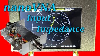
- In this video I will be showing you how to use your nanoVNA in stand alone mode to measure the frequency response of what was *supposed to be* a 50 MHz bandpass filter that I threw together.
This filter was supposed to have a 50 MHz pass frequency.
I discovered that one (or more) of the unmarked components were not the value I expected them to be, so the reality of this filter is somewhat different than planned. How different? You have to watch the video to find out.
Included in this video are
* Set up the nanoVNA for a frequency response (through) measurement
* Proper VNA calibration
* Make the measurement results more readable by changing the SCALE.
See below for the time markers ...
==========================
Filter Autopsy Results ...
==========================
First, this was a true "throw-together" filter, built without regard to various topologies and the like. So, its response will not adhere to any given standard response.
Yes, the component values were different than expected.
I measured the components in place (I know, not recommended for best accuracy).
This included a wire jumper (AKA: inductor) which was part of the implementation.
After putting the measured and adjusted values into the LTSpice model the estimated theoretical frequency response was
f1 = 27.19 MHz, f0 = 45.037 MHz, f2 = 78.29 MHz
The measured frequency response was
f1 = 27.1 MHz, f0 = 45.1 MHz, f2 = 76.6 MHz
I still do not quite get what is happening on the upper side. 1.69 MHz dif???
Nonetheless, for a thrown together filter, it is ... 'OK.'
======================
=== PROMISED LINKS ===
======================
nanoVNA Official Site (so they claim)
nanorfe.com/nanovna-v2.html
nanoVNA Manual (with menu map)
nanorfe.com/nanovna-v2-user-m...
Purchase nanoVNA V2 Plus 4 at
www.tindie.com/stores/hcxqsgr...
======================
==== VIDEO LINKS =====
======================
VIDEO: VNA Foundations (first video in the series)
• VNA Introductions: Wha...
== THIS SERIES ==
VIDEO#1: nanoVNA: A Practical Menu Walk Through
• nanoVNA: A Practical M...
VIDEO#2: nanoVNA: Measuring the SWR of an Antenna
• nanoVNA: Measuring the...
VIDEO#3: nanoVNA: Measuring the Input Impedance of a Filter
• nanoVNA: Measuring the...
=======================================
----------------------------------
Time Markers for Your Convenience
----------------------------------
00:05 Introductory Comments
02:00 Step 1: Planning
02:05 The Electrical Side
04:10 The Mechanical Side
05:13 Step 2: Measurement Preparations
05:16 Setting up the nanoVNA
05:22 The Frequency Settings
06:09 The Display Setup
06:20 TRACE setup
06:50 Setup TRACE 0
07:00 CHANNEL setup
07:28 FORMAT setup
07:56 MARKER Setup
08:11 Select the Markers
08:34 Connecting Things Up
09:01 Calibration
10:21 Final Preparation: Connect to the UUT
10:32 Step 3: The Measurement
10:32 Changing the SCALE
11:22 Marker Movement for Measurement
11:55 Finding the Pass Frequency, f0
12:07 MARKER SEARCH function
12:12 Select the Marker
12:37 Invoke the SEARCH function
12:56 Measurement Results
12:57 The Pass Frequency, f0
13:19 Low End Response: MARKER 1
13:39 High End Response: MARKER 3
13:59 Comparing Results with Theory
14:59 Final Comments and Toodle-Oots


Some of this goes right over my head. I have a Nano VNA-F and from your tutorials and a few others I am starting to understand how to use it. I even did a short presentation to my club and they didn't shoot me down so I reckon I got it about right. And we have some real electronic experts and I'm just a now retired mechanical engineer by training. Looking forward to the next one as I also have a pre amp stage to test out and I'm not entirely sure how to do it. Thank you Ralph.
Yeah, it takes time to sink in. Learning this stuff is not an overnight thing. Oh, and please note that I have a series of VNA introductory videos that goes over all the basics like terminology and the like. Here is a link to the first video in that series: ruclips.net/video/8IhJMGxU5xA/видео.html
Maybe some of that will help?
You are very welcome! I totally enjoy being a help to folks! 🙂
You know it's going to be a good day when Ralph posts a new video. Thanks Ralph! Learning is FUN.
🤓Thanks! ... and you are welcome! Yes, learning IS fun! (and it keeps your brain healthy, too!) 🙂
I like theory videos but the more interesting content is exploring why things don't match what you expected, that's where real science/engineering comes in. I appreciate the videos and explanations, I recently purchased a NanoVNA to get a more hands on understanding of various concepts like how ground plane size and material proximity affects performance of various antenna. I find reading books and articles is a good start but I need to be able to play with test equipment and components to build a more intuitive understanding, it's been a cool tool so far and your videos have motivated me to become more educated on these topics.
Looking forward to the upcoming video on measuring a preamp.
I do a lot of the same stuff! Have you tried virtual antenna experiments with an antenna modeling program? I use 4NEC2 (because it is FREE). I usually do all the modelling and experimentation virtually before I implement it in real life.
I have a number of videos on how to use the program. Here is a link to the first video in that series: ruclips.net/video/Zd6BT558YRA/видео.html 🙂
Great, thank you for your video. I'm starting to measure what I'm building:) At the mememnts balluns only. But this is ultra helpfull. Thx again.
Thank you! ... and you are very welcome! 🙂
Fantastic video! 😊 73s
Thanks, man! 🙂
Ralph 👋😎
Thanks! :-)
I don't think it's as bad as you made out. I generally like to look at the location of the passband to estimate the quality of the filter rather than the center peak. Since the -3dB values are pretty good, I think the filter is overall pretty good. Just remember, a small bit of parasitic capacitance could move the maximum point a good deal considering how flat the passband is. Looks like I'll have to get a nanoVNA, as it looks like an interesting tool. Cheers!
Thanks! On top of all of that, there is also a lot of stray inductance in there (like the jumper!). Totally an UGLY implementation clearly not intended as something I'm going to keep. I re-engineered the filter for a lower frequency range (for fun and sanity) and the final frequency response turned out real nice.
I think you would have a blast with a nanoVNA! 🙂
👍Thank you sir.
You are welcome! 🙂
Thanks for making all of these great videos? I wonder how you can check an I.F. transformer on an old (1940) radio with a VNA? No videos or anything available on this subject that I can find. Take care and 73!
Well ... first you would have to take it out of circuit. For a quick check, you could just connect things up. Be aware of the signal voltage level limitations that may or may not exist for it. You MAY need to attenuate the port signal to accommodate those limitations.
For more precision, you need to determine what the input and output impedances *should* be so you can match impedances in the measurement. The proceed as shown here. Check out the video on the making measurements in a non-50 World (ruclips.net/video/dgDS4rjb-GU/видео.html). This should help on this. 🙂
@@eie_for_you Thanks!
@@W1RMD You are very welcome! 🙂
please make videos about how to measure active filter used in frontends(88-108 mhz). or if you have any suggestion...
Well you're in luck! The very next video that is coming out (in two weeks) is measuring the frequency response of an active device. I will be using a 20 dB receive preamplifier for the demonstration which operates in the 144-148 MHz range. 🙂
Hello, where did you get N-type open/short/load standard connectors? Any helpfull link/name? Thank you, 73
Well...depends on the quality you are looking for. The hard one is the load standard. A good quality N-type RF termination like this one (www.mouser.com/ProductDetail/Mini-Circuits/KARN-50%2b?qs=xZ%2FP%252Ba9zWqbbyDyxB2ryNg%3D%3D) is probably sufficient for a lot of what we do. My first short and open standards were just N connectors. The open was the connector without a center pin. The short was a connector with a MASSIVE short between the center pin and the body (I used some braid out of some coax). I made the semi-mistake of buying a kit through Amazon. The short-open was amazing (that is the two ended one). The load was TOTALLY BAD NEWS. I dropped back to my 50 termination and threw the one that came with the kit in the trash.
There are a number of DIY calibration kit articles out on the internet as well. If you do decide to create your own load, DO use surface mount resistors. They carry a whole lot less RF baggage than their leaded cousins.
If you want a real calibration kit that is professional quality, then you are talking MAJOR $$$. You can drop thousands of dollars on that one. Because I have a higher end VNA, I wanted a better calibration kit, but I didn't want to spend that kind of money on one. I found a *reasonably* affordable one here: www.kirkbymicrowave.co.uk/Sales-and-Services/Vector-network-analyzer-calibration-kits/N-calibration-kit/. $680 USD. Hope all of this helps. 🙂
@@eie_for_you Wow, Thank you very much for you help:) This will help me a lot. 73
@@zygmunt73 I am very glad for that! 🙂
Haha. Already adjusting theoretical prediction by changing values used in calculations. Knowing component values accurately is step zero.
True that! And this was just a throw together filter for demonstration purposes. The values were assumed based on their source (the marked container they were in). Oh well, if this were a real project to create a real filter for a real end use, then several things would have changed including the really crude implementation and the absolute determination of component values and their potential tolerances both in value and as they respond to temperature variation in the anticipated application environment. 🙂
@@eie_for_you I'm sure you could do all that. Just need to get an lcr meter and do things in order.
@@jspencerg I prefer to use my Tektronix VNA when values matter. In this case ... not so much.