2$ LiPo Charger & Boost Converter? || TP5410 Test

HTML-код
- Опубликовано: 3 окт 2024
- You can get the TP5410 board here (affiliate links):
Ebay: rover.ebay.com/...
Aliexpress: s.click.aliexp...
Amazon.de: amzn.to/2uMC6PT
Support me for more videos: / greatscott
Previous video: • Electronic Basics #30:...
Facebook: / greatscottlab
Twitter: / greatscottlab
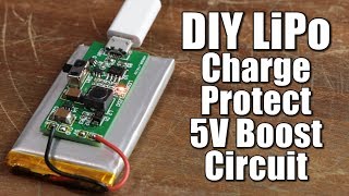
In this video I will have a look at the wemos d1 battery shield that "supposedly" can charge up a LiPo battery and boost its output voltage up to 5V. I will determine all the important features the board offers (like overdischarge or short circuit protection) and also test the efficiency of the boost converter.
Music:
2011 Lookalike by Bartlebeats


'First off, I desoldered the pesky LiPo connector.'
That's my man.
Enrico Rovere 😂 I bought a bag of them connectors
Careful with these modules, mine came with the wrong polarity connector!
why don't you ask some of your audience who are native chinese speaker when you have to read some chinese datasheet?i'm from Hong Kong,and i'm willing to help you
tutorial arduino Commenting so he hopefully sees this
tutorial arduino maybe you can ask the manufacturers why they lie about the specs of this board....
Can't agree more with Srigi. Google Translate app is an invaluable tool and a must-have app for anyone working with Chinese components.
also its sometimes hillarious if you read it out loud what google translate spits out.
If you have chrome, you can also install project naphta, which can translate text in images (if you have an image, of course. unfortunately it doesnt work with pdfs). If you have a pdf, you can upload it to google drive, open it with google docs and translate it (tools>translate)
happiness is getting notification from Great scott
Thanks for the extensive testing. I was zoo lazy to do that. The missing protections are common for the tiny lipo protection circuits on the battery themselves. So there won't be a problem in the most cases. I rather keep the connector. It's a standard JST. You can crimp a counterpart to your battery and then it's easy to disconnect.. which will happen more often
Nice work, it would be neat to see the equivalent practical tests done on the $20 board, and see how accurate the advertised specs are.
I like how you made the components de-solder themselves at the end
This is brilliant. It's hard to keep up with all the new boards that are available, especially when they don't have proper documentation. More like this!!!
Me: Buys the module... "it charges the battery Yey!"
GreatScott: "The output current is constant.... But once i lowered the input voltage to the nominal voltage..."
Me: ......
My ultimate wish is to assist GreatScott on all his projects (want to learn so many things from this man)
There are lipo chargers built in battery case on ebay (USB Portable External Backup Battery Charger Power Bank For Phones) , they cost less than a 1$, and they have very nice charger and 5V booster , and both USB ports for charging and discharging. I often buy those and just take out that very small pcb with both ports. They working flawlessly. Maybe in next video I present those, you gave me idea, ty GreatScott . Thumbs up from me as usual.
Notice that the chip itself is just a boost driver chip.. So, VOUT, is actually input pins (for sampling). For battery to VOUT(or SYS), there is not any protection.
1. This chip itself has overcurrent protection, but it's for the chip. If you short the SYS, it just like you are shorting the battery...
2. When the voltage is lower than setting (2.7v), it stops boost, and as the topology, it just connect battery to SYS directly. So their is no over-discharging protection.
3. Other protections are just cut off Vin at some conditions.
4. There is a circuit in datasheet comes with power path selection. This one you get is not suitable (but can, due to it have a diode connect from 5v in to Vsys) for charging and providing power at same time...
Yes.
First, I've never used this chip. So I'm just analysing these things by some facts that I know...
It can be just the problem of this kind of IC, the manufacturer is cheating about the values...
But consider that 700ma to 990ma(min) is too ridiculous, I think the poor PCB design maybe the main reason.
According to the datasheet, the charging part is a Linear regulator (it's not buck reuse the coil, it's a linear regulator...) which do not have a good efficiency and release heat. (We are talking about a 5V to 4.xxV LDO... with 1A)
The chip will limit the current by measure the temperature. (in case it goes too high)
In the datasheet they have warned that a bad heat design can result in lower charging current. So they recommend to use the copper on the bottom side as the heat sink by connect the back metal part on the chip to the bottom GND layer through vias.
From the picture of the product on the ebay, I can hardly see any via on bottom layer that connect chip ground to the bottom layer... (I can see a hole at 7:24 but I'm not sure if it's a via...)
Not mention they run the gnd wire under the coil...
As a comparison, you can look at the reference PCB design from the manufacturer www.tpwics.com/nd.jsp?id=24&_np=2_403
- something wrong, removed -
- something wrong, removed -
I'm not talking about the wide of pcb trace...
I can only find θja for this chip with no idea what the design is...
But it would be affected by the design and diminish the current.. But I cannot say anymore about this unless I buy one of this board...
Typical LDO like AMS1117 have a huge metal heatsink that almost as big as the battery chip itself... That's not the same story...
145℃ is max junction temperature (in limit mode it's 120℃) and in the figure of "complete charging cycle (2:45)", datasheet says θja = 130℃/W.
But I don't think with well thermal condition, θja would be so large...
So either the value is wrong or it means some other condition...
Thanks for showing us this board and testing it so well! I like the idea but will wait for better versions to come out that address the significant issues this one has.
Lol. I like how you got all bigclive on it at the end with 12v.
I have always thought there should be a cheaper alternative to PowerBoosts. This would be good for a little microcontroller project, which is exactly what I was looking for.
I was waiting for your video today
And luckily you uploaded one today.....
this is more practical, but if you need more power on the 5 volt line it is better to use a separated boost module
Definitely
DIYelectronics Agree with u
DIYelectronics and it's still 2 dollars to get both on ebay
DIYelectronics Can you recommend a reliable one? I got one from Amazon but it's crap: an overshoot of almost 23 Volts for almost 1 second that fried my IC's....
Good video!
I'm wondering... Why not just use the circuit in a cheap, single cell battery pack like the ones from the dollar store. They charge the battery and boost to 5V on output, they have built-in protection(usually), and they come with a battery you can use elsewhere. Even the case can be useful!
Robert Cartier true
They are based on the TP5400 IC, so the behavior should be similar. Only difference though is that they use a 6.8uH inductor instead of the 4.7uH on GreatScott's board.
Every time look at your so detail and focus project work ready impressed
Yay new Arnold Schwarzenegger video
captain?
@@BlueClefto I think he's referring to the german accent of GreatScott, of which Arnold is very famous for.
@@carlotta1337 But The Arnold is Austrian
@@noahhastings6145 True. I had him speaking German in mind, hence the mistake. But the resulting accent is still pretty similar^^
I like the way you teach. 👍
Really digging that rework technique at the end!
when will you make a video about electromagnetic levitation?
It is on my to do list. I can not give you an exact release date.
GreatScott! Oh yes!!!
Awesome...would love to see it!
Hi
Have you ever thought of using small USB "Power Bank" circuits ? It's a great solution and it work perfectly for me ! Cheap, Small, With a screen or not, overcharge and discharge protect... (Depending on the circuit selected)
In addition, they are very easy to find online or in a local store 🙂
The charge current can be set by changing the resistor between pin3 and ground. But the output current is not setable. Over discharge protection maybe can add with an external mosfet. This chip is only used by cheap powerbanks.
Powerbanks posess this kind of circuit, but smaller. Just open one of them and you'll find a 10850 battery (LiPo/Li-ion) as a bonus, extract the circuit, it's really small and has USB-A output and micro USB input both 5 volts regulated (usually).
I do electronic projects a lot. Besides, I am one of your Chinese fans. If in the future you came across some Chinese websites or data sheets, I am willing to help you!
I can also help you translate your shows and upload them to China's major video sites if you want.
I have a suggestion, do you have a more efficient way to make a certain frequency square wave power supply? Thank you!
Just a thought... Have you tried testing the maximum output current with the battery? The Input impedance of the source (battery vs bench power supply) makes great difference in the performance of the boost converter especially under load. I'd bet, the battery handles the current spikes from the boost converter better than the output filter of the bench power supply you are using (and don't forget the current protection kicking in from time to time). At least you could try placing a big (>1000uF) low esr capacitor at the battery terminals when testing with PSU and add a series inductance between the capacitor and the PSU. Otherwise, great video. Thanks!
he is so happy while saying good bye closing up the video and getting the board just so fucked up that smds unstick appart... sounds as an instant like for me lol
@GreatScott! Nice video Scott! This though did not work for me for the following reasons:
1. output is not constant 5V, it is USB voltage - 0.2V.
2. without USB voltage, it gave 3.7V or the battery voltage as the output, without any boost.
So, I'll go back to the first solution that you showed - boost circuit + batt charging circuit.
Maybe I'll look to combine them as you showed in one of your other videos.
Thank you for making these amazing videos!
Gave me confidence to make my own LiPo powered projects :) (y)
In the outro of this video I saw your quite interesting technique for desoldering SMD components. Looks much easier than fiddling with a soldering iron! ;-)
Some TPA3116 amps .. those are usually riddled with problems .. the chips are awesome though
I know it was all for the point of the video, but you do know the battery you chose (like most Li-Ion packs you buy today) already included a cut off and low discharge circuit? I think that's what the board was on the Li-Ion pack. But I don't know if it protects against shorts.
Gadget Review Videos I'd say: With electricity, you can never be sure enough ;)
Wow !!!! exactly what I was searching for. I was confused that Is adafruit's 1000C is worth of its value ? After seeing this it is clear now. Thanks for your time and efforts. Keep going.. Love from INDIA.
Thanks mate :-)
The real question is: Will it blow up my cheap lipos and set my house on fire?
pepper669 Probably
Most likely...
Yes, please. And upload video of all that.
I sure will! If I can.
As he said, there is no high risk of making fire by charging, but if you overdischarge batteries may malfunction.
I am Chinese,if you like,I can translate something on the data sheet for you.:)
Looks like GreatScott developed a new desoldering technique called "overvoltage desoldering". Maybe I should try it some day.
12V Auto desoldering feature included, nice :-)
I love this kind of videos! Me and probably a lot of people in your audience buy this kind of cheap stuff from chinese sellers. I would really enjoy more of these tests. Keep it up! :D
Hi
I am pretty sure you can translate any chinese datasheet using google translate. There is an option to upload a pdf file and translate the whole document. It does a pretty decent job, so dont let the chinese datasheets discourage you!
Good thing is that it is not difficult to find a LiPo with integrated short circuit/over discharge protection circuit. They are around 10 bucks in sparkfun/adafruit
Nice comparison !!! Good job there!!
You should check one of those Regulated e-cigarette mods. Evic VTC Mini for example would be a great thing to test, I'd love to see what type of circuit they use to regulate temperature of the atomizer resistance. They have this thing called Temperature Control, and Voltage control, and even bypass mode which theoretically acts as if the mod is outputting the Voltage of the battery .
Man, You really did a Lot of work there. I was before something to recharge the Lipo,so You could simple use the Voltage balance on direct charger and output 3.7v to lipo,right? Thanks for the vídeo,i learned a Lot...
These videos are gold
You should used powerbanks modules, they are faily cheap, can provide around 500mA at the output of the boost converter and around 1A of charging current. And also they have the battery protection circuit. I have been using these circuits for a while and they work like a charm on all my portable proyects with LiPos and 18650 Li-Ion battery cells. Anyways, great video, as always
Great video, really interesting as I just picked up one of these to look after a lipo powering an esp8266 but got utterly confused by the data sheet (lesson learnt there). I'd be really interested to hear your thoughts on over-discharge protection methods, chips and applications!
Another alternative would be buying one of these DIY battery charger boxes which basically come with the case, get the circuit, desolder the battery connection terminals and you are good to go :)
Here is an ideia. Test those 12V output USB cables (5V input) that are on the market to power a 10W LED. They are rated for 800mA maximum current, they should be able to light said LED without needing a driver, resistor and so on.
I have noticed many devices that need charging, due very poor when charge voltage is below 5v like 4.6. I would like to make a boost that can supply 5.5v 3A. I find most chargers are poorly regulated at 5v output. The regulated ones maintain 5.1 and really makes a difference in charge times. USB to Micro cables are a different story and vary greatly too.
Nice vid. I would like to see a similar circuit with auto-shutoff to protect LiPo battery from over charging cuz too often I forget to unplug them and ruin the battery. Not to mention the danger of over charging.
Thanks for that. I was just looking at boost converters for just this purpose.
nice one, thank you! It would be awesome if you could make a video about transformerless power supply design, you know the one they make with capacitors ( sorry my field of study is computer science not electronics :D ) to convert 240v-120v AC to 5V DC.
Kamran Aghlami no transformer means no isolation, if a fault occurs you could potentially have line voltage in your circuit and that's deadly
@rogert151 you are right, see? I thought this would make a good topic to make a video upon since the name is very tempting for some one who does not know a lot and who is trying to make lightweight and small circuits where transformers are too bulky to consider.
I'd like to see musts and mustn'ts of such power supplies, formulas to calculate power delivery and such.
and of curse I can google all of that, but such video is a need in youtube since there is not much already and our fellow friend @GreatScott! is brilliant at explaining stuff.
So it seemed like a good idea to me to ask for a video like that, so i did.
(apologies for broken english)
@Jan Ciger Well I have failed to die by electrocution a couple of times already, enough to understand what I'm doing when I'm around main's lines, (or is it ever enough?) thanks for the notice though.
I've heard some about how poor they perform, that's what I'm seeking. how Good/Bad of an idea it is to use them, dangers and hazards, why they exist then, formulas for power delivery and such.
(apologies for broken english)
It would be good to see you experimenting with some higher power devices, ones that can source a larger current and what measures you might take to handle it.
More than 600.000 subs getting close to the 1.000.000!!
MT3608 also has a high no load consumption so it may require a switch
There are super small boards for power banks, they give up to 900mA at 5v (rates 1A) charge your battery and have discharge protection
Nice work, I've got some of these in my projects, so it's good to know I should only use protected cells!
And I agree, the Lipo connector is very pesky, being the wrong polarity! (At least on mine anyway, didn't notice whether yours was as well.)
I wouldn't rely on those numbers or anything on eBay shipping from china, however, good job checking the circuit
I like it how you just kill it with 12V like "Nah this ain't working for me"
You can see the number of sold TP5410`s in the last hour on Ebay increasing after your Video xD
You should buy constant current load for tests like this
Nice video, but my conclusion, you chose this board for compact size but still need to add overdischarge protection, so back to square one. I appreciate the review tho. Thank you.
Although you seem disappointed in the 750mA vs 1A charging current, realize that the battery is part of the system, and had you used a higher capacity battery or 2 of those in parallel, you would probably achieve the expected 1A charging current. Good video, as usual!!! ;)
With LiPo battery, you cannot just connect two and be done. The entire charging and over-discharge protection circuits has to change.
Hey! I think you should build/test some laser engraver. I know it's not the cheapest one but definitely worth the efforts. There is many opensource platforms which do the job very nice. I've build one from old dvd drives and it's more like a gadget but there are super cool setups from china with 2, 5 and even 7W lasers... but it costs 200-500$ so it's actually better idea to buy some specialized CO2 plotter.
Triacs and circuits involving them in a more in-depth video would make my whole year. I simply can't get any of my triac circuits to work and is also something you can't find easily on youtube. Nevertheless, keep up the great job man
I made a basics video about triacs. Maybe it helps.
Yeah i already watched it, however i don't have an arduino to spend on phase angle control, i've been trying the capacitor/ potentiometer and diac at the gate approach with no sucess though
Can you make a video on what parts you always or often keep at hand
Thanks for this video. I've been looking for an economical way to power some basic LED switcher and seven segment displays for some integrated edge-lit acrylic signs. I hate the idea of cables running from a desk so this lipo+boost converter seems like it would be great.
Testing different circuits efficiencies charging lithium ion batteries from solar cells would be cool. TP5000 might be a good choice based on my own research. Hope this interests you.
I often use the tp4056 battery charger in combination with this exact same boost converter, the problem is if you use one with the protection circuit, let say your load is more than 5Watt the protection will activate and you could not power it. So I prefer to use the tp4056 without protection circuit. I just ad a battery level gauge with four led and comparator.
But in most case the boost converter stop working before the battery is drained too low.
You should make a video about making a short circuit protection circuit without fuse!
On my to do list
Thank you for your answer!
I like how in the end of the video you showed a clip of you taking the tested circuit board apart, made me laugh a little.
And maybe make a DIY video on how to make a circuit like the one you were just testing? If you havent already. I havent exactly looked through your videos to find if its already been done. Lol
I have not made a DIY version of such a circuit.
GreatScott! I think it would be interesting, as far as price comparison and how it works compared to the market brands
Another idea, you could make a controller circuit for an AC motor, like the one you would pull from a box fan
Excellent, in most cases the most common scenario is over discharge and with LiPo batteries going bellow 3v is not a joke, they puff, explode and burn. Would be too hard to add at least that protection?
I'm impressed with your knowledge..! You know you're stuff inside out. Gettings from USA!
at the ending of the video, are you trying to show that the board will achieve high temperature easily?
Thanks very much for what you do . . . . .I am new to your channel and as I watched my first video I thought GREAT SCOTT this is wonderful stuff. . . . .
You are very professional and i like your videos ... keep up the good work my friend
Very useful, thank you! I recently touched these kinds of solutions (for portable DIY oscilloscopes projects), so , your tests - good to know! :)
P.S.: that's one heck of a hot summer in Germany, judging by the end of this video... :D
Really, really nice. :) It would be great to have something like the TP4056 to 2s and 3s batteries, but nothing yet. :/
How about electronic basics about transformers
Like flyback transformers, microwave transformers, and maybe even car ignition coils?
hi. Thanks for the detailed analysis as usual. I bought a couple of these WemosD1 modules for my project exactly with the intention to have one module cover over discharge, charge and boost. When I got them and tested - I realized WemosD1 drains the batteries through this module down to 1.6V - what a major disappointment! I think without discharge protection these modules are useless.
May I suggest to add to your title "Wemos D1 battery shield" so that others looking for a review of this shield would find your video? If I saw this before - I would not have bought the pair.
Close but no cigar, shame it was a great price and I was ready to buy some.
I spent 8$ at wallmart, a portable battery bank for a cellphone charger. 3.7v step up to 5v 2amp. I removed the 2000mah battery and connected my 220mah for my small drone project. The circuit has protections including a temperature sensor tape to the battery.
I still haven't found a step up module that i can use with my esp32s3 drone project. Everything looks to heavy or fails to provide 2amp.
GreatScott, make a series of video about electric car controllers (AC PWM)
from battery to ac, I think it could also be used as inverter for solar power projects
is there a (easy) way to change the output voltage? maybe by changing the resistor values? could be very useful as you may need an energy and space efficient way to lower the voltage. Great Video as always
from how i understand the datasheet, you can't. you can only change the charging current. between 80 and 1000 with a couple of steps in between.
Damn google and their algorithm. My old led flashlihght just detonated his capacitors and i googled for the exact components you are using in this video to convert it from lead acid to lipo battery.
Then your video appeared on my suggestions.
It's my birthday today and my dad got me a FPGA chip
Allen Chellasamy wow! lucky!!
Congrats dude. Have fun making nand gates and stuff on it
What'd he get you this year?
The coolest video I’ve ever seen!
Maybe try making your own lipo charger and booster
You should make a function generator or an analog synth
I had a quick look at the translated chinese pdf and noticed the following:
"If the BAT pin is less than 2.9V, the charger trickle
precharge mode. In this mode, TP5410 provides a constant current
charge current is 1/5, so that the current and voltage up to a safe
level, for full current charge."
"Lithium battery voltage automatic shutdown
Lithium boosting circuit with voltage protection function, when the
battery voltage as low as 2.7V, TP5410 will automatically turn off the
booster. When the lithium battery 3V restored to more than cancel
shutdown state, boost recovery efforts."
The chip does what the spec sheet says. Except for the output current. But then it could be the heat sinking or the layout
need to see your diy power loger in a cabinet .
Try make a teardown on a power supply. That would be great.
I'd really like to see some oscilloscope giveaways, especially if I get one!
Late, but in this case, would the original idea of using the TP4056 protection circuit combined the boost converter be the safer and more reliable choice?
Seems so. I wonder if they improved their design by now. I really need the full 1A output.
Hi,
Thanks for videos, great tutorials.
One Topic for Next tutorial if you have interest.
You could show how to convert old in ear or on ear headphone as a buzzer for a project by sending signal as PWM via transistor from microcontroller or timer.
I have many old headphones around, and use them for projects as signal interface where I can hear command confirmations.
For example beep sound on button click.
Hello GreatScott, as a long time viewer I'd like to point out that you are really doing a great job, one can always rely on your expertise and your great videos.
I also happen to be from Germany and wanted to ask you where buy your LiPo cells, chinese eBay sellers are not allowed to deliver them to us, as far as I know.
Do you have any reliable and inexpensive source for those?
Maybe you could do a quick tutorial on how to reuse the batteries of old powerbanks with new charging circuits and such when the old are broken, because I still have 2 broken powerbanks laying around and don´t know what to do with them.
Can I use this to charge li ion batteries?
Yes
Thank you for your answer!
Lipos *are* li ion batteries.
superdau not true, a lipo is lithium polymer battery, which is different from a lithium ion battery
Robin Boots The chemistry is the same. They are the same battery just different forms.
after 7 mins you murdered the module!! why did you do that amigo? when am i going to see you demo a don smith wireless resonance 1/4 wavelength charging?
I can live without a short circuit protection. But the lack of an undervolt protection feature this module is almost a show stopper