Helpful. My knowledge base does not include much about impedance, yet. Your video was helpful, because 1) you explained why matching is important/necessary, from the prospective of transferring power between two devices and 2) you showed how a) the matching network is constructed and b) how it works via plotting/calculator. I know that I need to learn more about impedance. However, it is easy to get lulled into just throwing an op amp into the circuit design to dance around the challenges of actually learning about impedance.
What a wonderful video, thanks for making it the way you did. I kept track of everything, but a few of your explanations were much better than I usually find in textbooks, and helped clarify some things for me.
The best impedance video i´ve ever seen, very useful the distinction of power and voltage and current and even better the simple explanation of how to use the smith chart in a basic way now I can use this In a problem that I found the other day testing an oscillator because I wanted to connect the oscillator to an RTL-SDR to check the SDR and the oscillator and the problem was that the SDR has an input of 50 ohm and my oscillator had another output impedance luckyly I found on the internet some methods to compute the output impedance of a circuit and now with this knowledge I can transform the 700 ohm output to 50 ohm. Keep going with the channel beause not much channels talk about this topics and yours its one of the best of youtube in this area. P.D.: I´m very intrigued about the new update with the new design of the bpsk transceiver.
Straight-forward and direct. I learned something here. Calculating Inductance is still unclear (and I need to master) but within grasp. thanks for posting
Nunca havia visto o casamento de impedâncias explicado como esse ajuste de tensão-corrente, muito bom. É tão difícil achar boas referências em RF, parabéns pelo canal meu caro, mina de ouro em conhecimento. Sucesso!
great video! Could you also make a comment about the difference between a transformer approach and a Capacitor/inductor network for matching impedance? What is to be preferred? Also, you have an amazing assortment of components in your lab! :D Could you comment of what you have there, and make a lab tour? Keep up the great work!
If you want to match only 1 frequency it might be good to use the LC matching, if you want a more broadband matching, like HF transceiver then the broadband TLT transformer might be preferred. After about 6 mins you see the notch, showing the specific frequency where best match occurs.
Hello, excellent video with your intervention, there was no doubt. Congratulations on the excellent electronics laboratory and I already liked the channel. Hugs and strength on demand.
Help needed! How do I match impedance of inverter16v AC output SOURCE to 16vAC isolation transformer primary, that I have to hand WIND, for 4 ohms load of 32v AC 6 amps secondary ? Do I use the ohms of primary 16v + 12 amps division or the resistance .06 ohms of inverter output contacts terminals at 20khz frequency? Voltage and turns ratio same as 1:2. The online formula for inductance value of turns requires reactance value in ohms , at the frequency of source.
For mini FM transmitter it's required 50 ohm antenna and cable. RJ 58 and RJ 174 both are 50 ohms. If I use RJ 174 cable, It would be perfect for transmitter or not? Could you please tell me this?
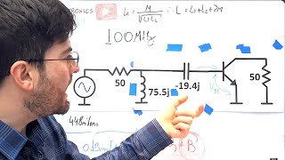
Nice question! I started the design with a Q of 15, to get a ~4Meg bandwidth around 50Meg. Following the design I saw that the capacitors needed would be 2 to 3pF, making it hard to demonstrate with adjustable trimmers. So I decreased the Q, relaxing the low capacitor values. Also, over a Q of 10 the inductor choke I used will not be ideal.. that part is made to be used as a choke and not a true inductor with high unloaded Q!
@@AllElectronicsChannel Even better answer - thank you! This is a really nice experiment and I would like to repeat it with some other matching network topologies :)
Awesome explanation of impedance matching network! My compliments. I have a question for you, please. Where I can find the matching network calculator that you used ? Thanks !!
Hi, great work on this content. It's good timing for me as I'm trying to design a linear amplifier for 70 MHz (4m Ham band). I am using MRF101an and hoping for 20 dB gain, 1w in 100w out. I have the 1 watt sorted (-; I have been using smith chart software to calculate the necessary values to match the output of the device ( I am being lazy and using 6 dB PI attenuator for the input so the preceding circuit sees a good match). I found NXP provide some reference circuits (closest is 50 MHz, and one at 81 MHz), they also give some values of Z load and Z source, I discovered I could use just series inductor and shunt capacitor. Why did you use an extra series capacitor? Maybe to give more flexibility for tuning, also I guess it works to decouple AC/DC? Anyway, again, thanks for this video.
Thank you! I don't know if it is easy to get 100W output with 1W input.. I used this network because is one I use a lot. The components values are close to real values, sometimes you get matching networks with very low capacitances/inductances.
Hello Gregory i would like to ask you about your directional coupler which you are using in the video ... could you please share the reference and where i could buy one .. the goal is to measure the output impedance of an small RF signal amplifier Parameter S22 .. thanks in advance .. Greetings from France
Hi! That is a unit I bought surplus, I don't know the exact code.. Probably any directional coupler will do.. Search options on ebay. That used in the video is a high power one, not the best for small signal amplifier.
Hello dear, good video, can you mention the website url for this circuit calculator you mentioned towards the later part of the video. Thanks for the valuable video and keep the good work up👍
Hi , i have an old Marconi Step attuator which has 75ohm input and output , i would like to convert it to 50ohm input and output..i will only be using it with cb radios , ie up to 30mhz. Can i use this approach? Much appreciated
For a broadband match you should use a resistive atenuator, that matches the impedance. Search for PI or T resistive atenuators. They will add an constant amount of attenuation in dB, plus what you set in your attenuation box. You should design the attenuator for 50 ohm at one side and 75 in the other. Using two alternators, one in each side of your box.
batteries typically have an internal impedance much lower than 1 ohm, so why do AC sources have such high impedances as 50, 75 ohm, isn't that a lot of Joule loss ?
It was a compromise for attenuation and frequency response in transmission lines. But this is not a resistive loss in the cable, it means the ratio of the voltage and current waves in the cable is 50
@@AllElectronicsChannel OK, so the resistor symbol inside "real source" diagrams does NOT represent an actual resisting element, but rather a power source characteristic. that was misleading. thanks for clearing it up !
how do you calculate the input impedance at the base of a bjt at rf. all examples i can find online use the beta * (re + Re) equation, but at RF the input impedance tends to be far smaller. el beta se reduce tanto en RF ??
Seems interesting vid but I just can't watch it due to all that quick cuts in the middle of sentence, it's so annoying it really makes it unwatchable :/
@@AllElectronicsChannel It's true!! "Fundamentos de microeletrônica", I had understood "Fundamentos de microelectrónica". Portuguese and Spanish are very similar. Thanks for your videos. (I'm spanish)
can we use a simple opamp buffer as the matching network, instead of designing an LCC circuit? Btw AWESOME video!! Please keep making such videos explaining very basics which we tend to forget in our engineering jouney.
For low frequencies yes! But you will not be increasing the transfer of power, you will be copying the signal with the opamp. It's kind of a different concept
@@AllElectronicsChannel As far as I know, buffers help prevent loading...so how is this different from impedance matching? Can you please guide me to a resource if you can't briefly answer here?
Impedance matching transforms the voltage and current profile of the source, so it can delivery the maximum amount of power possible. A buffer will copy the input signal and deliver power from other source!! The power will be delivered from the source that is powering the buffer, not the signal source.
Can we transfer this impedance theory on the power grid? Let's imagine à nuclear power plant delivering 1000 MW to the grid. If impedance of load is equal to generator impédance, we can say that the power dissipated in générator impedance is also 1000MW. I do not think it is the case. I think for nuclear power plant, we want genertor impedance as low as possible. There is a paradox in what you have explained.
@@AllElectronicsChannel thanks and this was a very good video.. I am embedded firmware engineer and I am trying to learn about radio tech and circuits and fundamentals so such tools are helpful
Why are you keep frame-zooming in and out? That's very distracting and unnecessary. Don't fast cut. You won't get far with hype-style video editing on an electronic channel. Don't be vague and don't do the air quoting gesture. You need to be precise with the words, or else the audience might pick a wrong interpretation. Otherwise you're good. Be yourself. This is a very promising channel, thank you, and subscribed! :o)


Support the channel being a Patron!
www.patreon.com/allelectronics
@@AllElectronicsChannel hello 👋
Helpful. My knowledge base does not include much about impedance, yet. Your video was helpful, because 1) you explained why matching is important/necessary, from the prospective of transferring power between two devices and 2) you showed how a) the matching network is constructed and b) how it works via plotting/calculator. I know that I need to learn more about impedance. However, it is easy to get lulled into just throwing an op amp into the circuit design to dance around the challenges of actually learning about impedance.
What a wonderful video, thanks for making it the way you did. I kept track of everything, but a few of your explanations were much better than I usually find in textbooks, and helped clarify some things for me.
I'm doing the IEEE IMS competition for this year and this video helped a ton. Thank you!
The best impedance video i´ve ever seen, very useful the distinction of power and voltage and current and even better the simple explanation of how to use the smith chart in a basic way now I can use this In a problem that I found the other day testing an oscillator because I wanted to connect the oscillator to an RTL-SDR to check the SDR and the oscillator and the problem was that the SDR has an input of 50 ohm and my oscillator had another output impedance luckyly I found on the internet some methods to compute the output impedance of a circuit and now with this knowledge I can transform the 700 ohm output to 50 ohm. Keep going with the channel beause not much channels talk about this topics and yours its one of the best of youtube in this area.
P.D.: I´m very intrigued about the new update with the new design of the bpsk transceiver.
Straight-forward and direct. I learned something here. Calculating Inductance is still unclear (and I need to master) but within grasp. thanks for posting
Thanks and welcome to the channel!
Nunca havia visto o casamento de impedâncias explicado como esse ajuste de tensão-corrente, muito bom. É tão difícil achar boas referências em RF, parabéns pelo canal meu caro, mina de ouro em conhecimento. Sucesso!
Thanks!
Thanks for the video, I now understand the importance of matching. I will use it to fit an antenna to the shield I am designing.
Nice!!
Really helpful 👏
great video!
Could you also make a comment about the difference between a transformer approach and a Capacitor/inductor network for matching impedance? What is to be preferred?
Also, you have an amazing assortment of components in your lab! :D
Could you comment of what you have there, and make a lab tour?
Keep up the great work!
Yepp!! I will do !
If you want to match only 1 frequency it might be good to use the LC matching, if you want a more broadband matching, like HF transceiver then the broadband TLT transformer might be preferred. After about 6 mins you see the notch, showing the specific frequency where best match occurs.
great work on this content !
that was superinformative
Hello, excellent video with your intervention, there was no doubt. Congratulations on the excellent electronics laboratory and I already liked the channel. Hugs and strength on demand.
For wideband applications use a 3db pad or step up / step down transformer
Really good explanation!
Glad it was helpful!
Good timing on this! (For me)
Help needed! How do I match impedance of inverter16v AC output SOURCE
to 16vAC isolation transformer primary, that I have to hand WIND, for 4
ohms load of 32v AC 6 amps secondary ? Do I use the ohms of primary 16v +
12 amps division or the resistance .06 ohms of inverter output contacts
terminals at 20khz frequency? Voltage and turns ratio same as 1:2. The
online formula for inductance value of turns requires reactance value in
ohms , at the frequency of source.
Excellent explanation
Thank you!
great stuff as usual
Learned a lot
🙏🏼🙏🏼👌
Dude you're Amazing!
Wow, thanks!
For mini FM transmitter it's required 50 ohm antenna and cable. RJ 58 and RJ 174 both are 50 ohms. If I use RJ 174 cable, It would be perfect for transmitter or not? Could you please tell me this?
Great video - thank you!! Please can you say why you choose 5 as the Q factor?
Nice question! I started the design with a Q of 15, to get a ~4Meg bandwidth around 50Meg.
Following the design I saw that the capacitors needed would be 2 to 3pF, making it hard to demonstrate with adjustable trimmers.
So I decreased the Q, relaxing the low capacitor values.
Also, over a Q of 10 the inductor choke I used will not be ideal.. that part is made to be used as a choke and not a true inductor with high unloaded Q!
@@AllElectronicsChannel Even better answer - thank you! This is a really nice experiment and I would like to repeat it with some other matching network topologies :)
Awesome explanation of impedance matching network! My compliments. I have a question for you, please. Where I can find the matching network calculator that you used ? Thanks !!
Nice info, thanks :)
Thank you by clearly explain this concept. So, I have subscribe now !
awesome and thanks a lot!
amazing content 👍
Thank you 🙌
Great, great video!!
great!
It's like a magic😊
🥰🥰
how to kno that wire is 50 oh and it also depands the thickness and legnth of the cable just in dc ohm law ?
Hi, great work on this content. It's good timing for me as I'm trying to design a linear amplifier for 70 MHz (4m Ham band). I am using MRF101an and hoping for 20 dB gain, 1w in 100w out. I have the 1 watt sorted (-;
I have been using smith chart software to calculate the necessary values to match the output of the device ( I am being lazy and using 6 dB PI attenuator for the input so the preceding circuit sees a good match). I found NXP provide some reference circuits (closest is 50 MHz, and one at 81 MHz), they also give some values of Z load and Z source, I discovered I could use just series inductor and shunt capacitor. Why did you use an extra series capacitor? Maybe to give more flexibility for tuning, also I guess it works to decouple AC/DC?
Anyway, again, thanks for this video.
Thank you!
I don't know if it is easy to get 100W output with 1W input..
I used this network because is one I use a lot. The components values are close to real values, sometimes you get matching networks with very low capacitances/inductances.
Beautiful
obrigado
I voice searched for impedence matching of physiology and i found this 💀
Are you Brazilian, I suppose? Great content! Do you have any channel in Portuguese also? Or any books, material or blog?
good, thank's!
I am really curious why you choosing Q of 5? Thank you for sharing.
It was a free choice for the components values I had.
The problem is that this does not work for wideband applications.
You can improve on that using more sections 😋
Does anyone know how to match the impedances of some EMG electrodes to an AD620?
The circuit always saturates or does not amplify anything
what about low frequencies as in the audio range....
For audio there is not impedance matching.. only voltage bridging. An audio amplifier will have very low impedance.
Hello Gregory i would like to ask you about your directional coupler which you are using in the video ... could you please share the reference and where i could buy one .. the goal is to measure the output impedance of an small RF signal amplifier Parameter S22 .. thanks in advance .. Greetings from France
Hi! That is a unit I bought surplus, I don't know the exact code.. Probably any directional coupler will do.. Search options on ebay. That used in the video is a high power one, not the best for small signal amplifier.
Ver um brazuka falar inglês num canal do YT é muito foda!
Woooooowwww
Seu canal é excelente!!! Muito obrigado!!!
Hello dear, good video, can you mention the website url for this circuit calculator you mentioned towards the later part of the video.
Thanks for the valuable video and keep the good work up👍
Thank you! Search for "web smith chart" !
Hi , i have an old Marconi Step attuator which has 75ohm input and output , i would like to convert it to 50ohm input and output..i will only be using it with cb radios , ie up to 30mhz.
Can i use this approach?
Much appreciated
For a broadband match you should use a resistive atenuator, that matches the impedance. Search for PI or T resistive atenuators.
They will add an constant amount of attenuation in dB, plus what you set in your attenuation box.
You should design the attenuator for 50 ohm at one side and 75 in the other. Using two alternators, one in each side of your box.
@AllElectronicsChannel thanks for the reply...I will peeps it 😀
Hello. How do you match nonlinear circuits, like diode mixers for example? To be sure that reflected power is low.
If you really need good match you place an atenuator in front..
What frequency was that sine wave on the scope?
I don't remember..
@@AllElectronicsChannel fair enough... that you are responding... was it in the RF range?
I believe that in the video I used something like 20 meg. The technique is useful for any frequey though
@@AllElectronicsChannel thank you!
the accent is so strong in this one and only 1y ago, gj
😆😆😆
spent the 3 first minutes completely puzzled about the concept of power source impedance, until I realized it only made sense in AC
Hahahaha yep!
@@AllElectronicsChannel but your explanation's really good. +1 sub
Ciao bel video, ma tu sei italiano? Nel video si vedono libri in italiano dietro di te? Complimenti bravo👍👍
batteries typically have an internal impedance much lower than 1 ohm, so why do AC sources have such high impedances as 50, 75 ohm, isn't that a lot of Joule loss ?
It was a compromise for attenuation and frequency response in transmission lines. But this is not a resistive loss in the cable, it means the ratio of the voltage and current waves in the cable is 50
@@AllElectronicsChannel OK, so the resistor symbol inside "real source" diagrams does NOT represent an actual resisting element, but rather a power source characteristic. that was misleading. thanks for clearing it up !
Yep!
how do you calculate the input impedance at the base of a bjt at rf. all examples i can find online use the beta * (re + Re) equation, but at RF the input impedance tends to be far smaller. el beta se reduce tanto en RF ??
Yep, beta reduces a lot. You can aprox. using Ft / freq. You also have capacitances Cbe and Cbc. Sometimes the only way is actually measuring
@@AllElectronicsChannel muchas gracias. )
@@AllElectronicsChannel could you point me to your video where you measure the input impedance of the bjt?
I think I do not have any video about it yet
Thanks Dear , which software you are using for impedance matching
I used an online tool , search Google for online Smith Chart
Seems interesting vid but I just can't watch it due to all that quick cuts in the middle of sentence, it's so annoying it really makes it unwatchable :/
Hey man!!!!!! You have spanish books, I've seen them!!!!!
Mines are in portuguese hahahahah
@@AllElectronicsChannel It's true!! "Fundamentos de microeletrônica", I had understood "Fundamentos de microelectrónica". Portuguese and Spanish are very similar.
Thanks for your videos. (I'm spanish)
Follow me on Instagram!! allelectronicsgr
@@AllElectronicsChannel I knew it!!! I follow you since your portuguese spoken channel, my friend! Show the world your contents!
can we use a simple opamp buffer as the matching network, instead of designing an LCC circuit?
Btw AWESOME video!! Please keep making such videos explaining very basics which we tend to forget in our engineering jouney.
For low frequencies yes! But you will not be increasing the transfer of power, you will be copying the signal with the opamp. It's kind of a different concept
@@AllElectronicsChannel As far as I know, buffers help prevent loading...so how is this different from impedance matching?
Can you please guide me to a resource if you can't briefly answer here?
Impedance matching transforms the voltage and current profile of the source, so it can delivery the maximum amount of power possible.
A buffer will copy the input signal and deliver power from other source!! The power will be delivered from the source that is powering the buffer, not the signal source.
interesting!!!!!!!!
Can we transfer this impedance theory on the power grid? Let's imagine à nuclear power plant delivering 1000 MW to the grid. If impedance of load is equal to generator impédance, we can say that the power dissipated in générator impedance is also 1000MW. I do not think it is the case. I think for nuclear power plant, we want genertor impedance as low as possible. There is a paradox in what you have explained.
If you have control of the source impedance, you make it as low as possible. If you have control of load, the best case scenario is the matched one.
@@AllElectronicsChannel so you should mention that in video
What was that online tool you used ?!
Web Smith Chart
@@AllElectronicsChannel thanks and this was a very good video.. I am embedded firmware engineer and I am trying to learn about radio tech and circuits and fundamentals so such tools are helpful
Amazing man! Welcome to the channel
Why are you keep frame-zooming in and out? That's very distracting and unnecessary. Don't fast cut. You won't get far with hype-style video editing on an electronic channel. Don't be vague and don't do the air quoting gesture. You need to be precise with the words, or else the audience might pick a wrong interpretation.
Otherwise you're good. Be yourself.
This is a very promising channel, thank you, and subscribed!
:o)
Tu é BR?
Thanks! 🙏🏼🙏🏼
What accent is this
Too much choppy editing.
This distracts you ?
Beautiful
Thanks!!