Adding a capacitor to a driverless LED and other tests.

HTML-код
- Опубликовано: 19 мар 2017
- A followup to the earlier teardown video on the driverless LED with an insulation test of the substrate and the addition of an electrolytic capacitor to the PCB to convert the rectified AC to smoother DC.
If you enjoy these videos you can help support the channel with a dollar for coffee, cookies and random gadgets for disassembly at:-
www.bigclive.com/coffee.htm  Наука
Наука


I don't know if you're aware of it but that flicker can cause seizures. I am currently helping to upgrade an entire building from florescent to LED. The florescent also have that flicker and were contributing to seizures. I probably spent almost a $1000 just testing bulbs and drivers till I found something that would work. For the most part it came down to finding a driver that had a capacitor to smooth out the frequency. We will finish replacing all the bulbs and drivers in the next week or so, but after that there is few of the standard screw-in light bulbs and I am considering just modifying LED bulbs by adding a capacitor. So videos like this are very useful, especially when it comes to understanding the problems I may run into.
240V Mains ➡ FULL BRIDGE RECTIFIER ➡ film in oil motor capacitor _(for heat tolerance and longevity)_ ➡ two of those COBs in series _(assuming the forward voltage is met)_
Dear bigclivedotcom, thank you for answering our comment questions so fast with this video! I learned a lot!
Clive - If you want to examine individual cells of any configuration of LED - try looking at them using a UV light source ... the phosphor dots flouress quite nicely. Makes it easy to spot burns. I recently converted a torch to use with UV resin glue and it's turning out useful for other things too.
That was interesting, glad you tried it to see what would happen. It was cool to see that the capacitor did actually remove the flicker and also the side effects it had on the rest of the electronics.
Thank you for this update.How about connecting the capacitor directly parallel to the LEDs?!
I just purchased two 30 Watt flood lamps. Thank you for your tearing apart for me. Very interesting videos.
Another great video. I have been wondering for long time if you had ever thought of teaching ? You inspire many people. And your humour makes it so enjoyable.
Thanks for experimenting! Good follow-up.
A smaller capacitor might allow for elimination of most of the flicker without pushing the chips that hard. I calculated that the cap should last for about 7ms (from the peak to the next time the voltage enough ( about 185Vish?)), and your 10uF would drop from 330V to 267V in that time, whilst 4.7uF would go to 196V (close enough?).
I calculated with crude numbers and assuming constant 0.09A current, but if you like to experiment, maybe try 4.7uF ...
EDIT: Also, the sinewave likely exceeds that slope for a while on the top, and caps might be bigger than specified (so good idea to measure them), maybe experiment with even smaller caps too..
Very cool, Thanks for the follow-up tests and explanations!
hi Clive
loving the videos, I'm on holiday on the island for this week staying just south of Peel would love to pop by and say hello.
big thanks
Daz in his campervan
Things like this are why I watch big clive. Bad idea? Lets do it!
Great information that you are sharing. It is very useful to me to see you revers engineer and then modify the circuits since to me has been a great help with my own experiments. Thank you for your great work and sharing. You saved me so much time.
The particular driver I was looking at has a temperature rating well above 100c, it may be that with a larger heat sink the LEDs will work just fine even with the wonky power factor and increased power dissipation at the chip.
Thanks for the follow up!
After adding a cap to smooth out the flickering, could you ad a resistor in series to the LEDs to limit the heat created by the constant on heat buildup of the LEDs? Also could a variable resistor be used as a dimmer controller?
So if you run the 220V version with 110V and smooth it, it should be fine?
Thank you very much, Clive. I highly appreciate your work in exploring and explaining this gadget. I will still have a very hard time, though, soldering anything to the tiny Rectifier legs?
I didn't know these LED modules existed; Have ordered a few for 'experiments' ... Good find Clive.
Hopefully this is just first generation for driverless, and the second generation will fix it. This technology looks like a good step in making LED technology cheapper and easier to enter more markets.
not really... the power dissipation in the LEDs and the current limit resistor/chip becomes too much.
I also found those questions interesting so I'm very glad you explored it, Clive!
Hi Clive, hello from Australia. Thanks for your great videos, I put your knowledge to good use when a capacitive dropper in a PIR floodlight failed and the switching relay just buzzed. All sorted now :)
The video on your quick test was excellent, are you able to demo some of your other bits n' pieces in future videos? I'm in the process of setting up a workshop and it'd be great to know the details of some of the wattmeters, hand tools and other interesting items of test gear or measurement that I should probably have (whether I need them or not!). Sometimes it's a matter of knowing these things exist so we can buy them.
Cheers,
Adam
In the previous video you said that the current was programmed to the chip by a resistor. If you increased the resistor, would it negate the extra power from the capacitor modification?
I'd imagine replacing the resistors would be very hard due to the silicone potting and aluminium core PCB. Certainly not worth the effort.
Jernej Jakob trimming back the silicone is easy enough and the old reflow trick of putting the board on an electric hot plate and use a hot air reflow pen to melt the solder. Don't underestimate Big Clive's persistence.
You will need dispass more power on curent regulator too.
Could you limit the power before or after the capacitor so lower the voltage?
it worked for flickering problem ? what was the best value for the capacitor of 220v 50W led ?
I would be very interested in further ways to stop these LEDs from flickering. What do you think about adding a capacitor in series with the LED with a capacitor across the rectifier as well? Or how about adding a big capacitor between the driver and the LED itself? This wouldn't probably be a lot less effective against flickering since the forward voltage across the LEDs would still ripple a little (depending on the capacity of the capacitor). But at least the drivers wouldn't be getting a peak mains voltage all the time. One might also try to decrease the voltage to 170 VAC, so the rectified voltage is 240 VDC. This may be an overly complicated solution to stop a 2 dollar or so LED from flickering. But I would still be interested in your opinion to different ways fixing the flicker.
Automatic thumbs up for taking the time to answer questions.
Could you put a couple of high power ceramic resistors heatsinked to the case to drop the peak voltage when using the capacitor?
Thank you for this and all your great videos. What if you put an X cap in series with the line to lower the current along with the filter cap maybe you could reach a balance that would correct power and flicker. I have 20,30 and 50 watt 110v versions with 144 leds each that look similar to yours. Haven't powered yet. Possibly the 60hz AC line here will make flicker less noticeable.
Hi, how about a external bridge rectifier, smoothing capacitor on the output of the external bridge rectifier, and put (2) LED lamp modules in series? Would that bring the temps down and make it more stable, while illuminating the flicker? There should be room in the case for both modules.
can you add the capacitor after the regulator chips?
Clive, what about adding a cap to a 240v driver less module and running it at 120v. And do you think it would handle dimming?
I know absolutely nothing about electronics and most of what Clive says goes over my head. But I find these videos oddly entertaining...
Hi Clive, in this video you had the capacitor across the rectifier. If the capacitor were across the array of LEDs instead, how would it have fared?
Wouldn't you able to use 2 with a voltage divider to get the power down so you can use a capacitor on each without overdriving them?
Ma full spectrum ones dont flicker according to my Nokia 5 cam but the ones I've tested 10w X 4 powered from 12v with boost converter upping the voltage I get the flicker from them.. I've added diy heatsinks to them they work very nice but they need some kind of connection with them save soldering them . Good video
for 50w driveless, what capacitor spec e use? thanks
To reduce the flicker without overrunning the chips or LEDs, fit a smoothing cap after the bridge rectifier. Then add a series cap in the mains feed with its value selected to return the power consumption to its previous level.
Would it be possible to use an inductor/magnetic ballast and some diodes to reduce the ripple? So it gets mains waveform and a phase shifted waveform?
Did you put some sort of thermal compound in between the LED backplate, and the casing/heatsink? Might get better thermal performance.
would adding a power resistor work to limit the voltage after smoothing?
How would a cap in series work 8:32, I didn't understand completely. Could someone go into detail, I am interested in trying this. Thank You.
With the capacitor installed, how would you make this circuit more efficient? If the power consumption is the same as before then how is it dissipating more heat? Does adding the capacitor makes the LEDs dimmer?
I wonder if there's a compromise value for the add-on capacitor that reduces the flicker enough but doesn't affect the power factor too much?
I have an outdoor balcony light, the G23 9w bulbs don't last very long.
I saw this video and wondered if I could wire one of these in, it has a 240v (5/7/9/11w) driver, would this work as the supply?
What about using like a 4.7uF low ESR cap to give some smoothing, but not quite so aggressive? Thinking about a balance between no flicker and a little.
Ok so if I ordered the 240v versions and used them on my 120 mains with the smoothing capacitor would it work better? I mean the rms voltage is much lower so putting that capacitor in there would just compensate for the lower voltage right?
Quinn Miller I would like to know as well!
If the peak (not RMS!) value of your supply does not exceed the LED string voltage, it will never light up. Considering there's about 70 LEDs a 3V you'd need at least at around 200V (absolute, not RMS) for it to light up at all.
superdau true
120V wouldn't hit the 180V needed to light the LED's properly even if smoothed.
Now if you swapped out the bridge for a voltage doubler using a cap and two diodes then you would be onto something :)
WRONG! Specks call for 86 - 265 vac.
I blew two of these 50w chips, because I tried to solder the wires on them while not mounted to a heatsink. The Insulation seems to have melted. As soon as I toch the back plate with the ground wire, my fuse blows. I soldered 4 of them, while already mounted on a heatsink, yes it is a little bit tricky, because of the heat dissapation, but those do work good, and the insulation is maintained. As heatsink for a 50w chip I use CPU-Heatsinks with fans. Hope I could answer the question from the beginning about the Insulation.
I am using these cobs and have been mounting 5 x 50 watt on an ally plate, with one cpu cooler on the back, the latest build tripped the RCB (MCB) in the house , not with earth disconnected though. Im not about to do that. Any thoughts? Continuity with a standard DMM shows it fine. So 2 questions if you folks dont mind,:
1. Is one CPU cooler gonna do it - no probs running previous builds this way, not too bothered on lifespan.
2. Any ideas why its tripping my trip, i did use exhaust putty to cover the live pads, which on my DMM shows infinite.
Im asking cos I want to build 2 x 250 watt lamps, repurposing some old parcans.
Would it be possible to reduce the input voltage with a voltage regulator and THEN connect the electrolytic capacitor that will increase the voltage up to the ideal voltage?
Those things are so cheap that a multi-kilowatt LED array might be amusing to build.
mikeselectricstuff q
h
Roughly 10kW per square metre, say 50% heat would be generated
5kW heat is 1litre of coolant water through 5'C every second?
Hi. Does the flickering affect the heating of the LED?
I had exactly the same thoughts regarding a capacitor to smooth out the flicker but I wasn't sure if these chips would cope with a DC supply, so thanks for answering that one. To get around the higher voltage problem I considered using three of the 110v units connected in series but I'm not sure how they will interact with each other.
A 230V led on rectified 115V would be more interesting. Under-running it would prolong its lifespan.
Jernej Jakob If you have a 115v supply then I agree, always assuming the rectified voltage is high enough to turn them on, it may be borderline in that respect. Like Clive, I'm stuck with nominal 230v, more usually about 250v, giving a rectified voltage of 325v nominal, about 350v in practice.
My concern is how the current limiting effect of one device would affect other devices in a chain. One solution might be to put a bypass resistor across each device to try to equalise the voltage.
Rectified 115V or around 160V peak won't be enough to turn on the LED-string of a 230V version at all. Maybe you get a glow, but for over 70 LEDs in series you'd need around 200V to get any useable light out of them.
Considering that the chips are apparently linear regulators (says so in the datasheet) and Clive was able to run them with a huge resistor in series, hooking multiple of them up in series should actually work. Sure, one of those will be the current limiting one of the whole string. But that's actually a good thing, because all arrays will run at the same current and be quite equal in brightness. There isn't really a need to equalize the voltages in the same way that you don't need to equalize the voltages on the LEDs in a series string.
It will still be a bad idea though, because the flicker of 3 110V versions in series on 230/240V will be worse.
What if you were to smooth the voltage with a modestly sized inductor (in series) instead of a capacitor? Wouldn't that smooth it without raising the voltage to the peak mains like a capacitor would?
When running two next to each other in inverted phase (L and N switched over) would it eliminate the visual flicker?
inverted phase would do nothing, both waves would have the peaks at the same time
so if i were to use a bunch of these all next to each other would the flicker be all in time with each other following the the ac wave form or would they be slightly different thus appearing less flickery?
i did have one of these driverless chips with solder pads in the circuit which at the time i did wonder if it was perhaps some optional filtering add-on
If they're all on one power phase, they'd flicker the same. If you had a 3 phase line, put them on different phases and would probably be no noticeable flicker
You have been lied to. Sorry.
What is the emc of thosed led's and how much rf to they put out and at what frequency, a shortwave radio will give a good idea of any problems.
Hi Clive. Have you seen the Gosun floodlights on Amazon yet? I've used a couple of the 30w daylight white ones and they seem pretty good and very competitively priced. They're quite a different design to the normal aluminium troughs and they claim to use cree LEDs. Just thought they might be worth a look.
Hi, Can anyone recommend a device that i can use to plug appliances into to check the current used amperage? - one that does an average over time would be great too.
Thanks :)
whats the equivalent to a non-led lamp per watt? (candles - lux) . can you compare this to an ordinary lamp?
Hey Clive, will a standard dimmer affect this LED any? I know you ran it on a very low voltage (something like 3, if I remember correctly, but probably not) to see the arrangement of LED chips, but the standard dimmers accurately control the LEDs' brightness?
It should work, but with an odd dimming curve.
how about running the 220 volt version on 120 volt with the cap
If excess heat and reliability is an issue (i have problems with flicker in side vision causing headaches very quickly) maybe a easy bodge might be to put 2 lamps in series? It would reduce output of each chip and lamp of course but increase longevity (running at just over 1/2 intended voltage) but how to wire 2 lamps in serise safely?
Hi Clive I'm not expert in electronics, but would it be possible to use say two of these modules together so they run at alternating sync, thereby no flicker ??
Peter Scharff two legs of power like in a house hold still have the same zero crossing point, but if you had 3 of them connected to different phases of 3 phase there might be an interesting result
No it would just be three phase power. You know.... What is used by industry EVERY DAY. (and they have the same problem.)
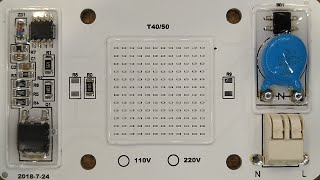
*I just got this LED from different seller for 120V, it looks quite different and seems to have testing points, also, the cover on chips is transparent, I could send you a full resolution picture if you want.*
Would changing that zero ohm link to an actual value help to limit the power so the chips werent running as hard and help, when the capacitor is soldered on the board, to bring it back down to a power similar to before the capacitor was added?
Nepal Plush Yes, but you will be dissipating quite a lot of power in that new resistor, meaning you could not just insert another chip capacitor as it would need to be a high dissipation wire wound type resistor.
Great for a Floodlight conversion
I just ordered a small pile of these chips, and I'm hoping to pull DC off the board to power a 12v pc fan for cooling. Any ideas?
Clive, do you work off of a script or are you just naturally well spoken and knowledgeable?
I usually just go with it. I can talk for hours about technical stuff.
A friend and I bought some of these Chinesium LED lights, they claim 50W. They consume about 35, and get smoking hot. After a while, get a 'black dot of death' in one or two of the LEDs. I put a motor run capacitor, ( about 5 uF ) in series with the incoming power. Dropped the power consumed down to about 17W, and the lights run much cooler. Only been on the test area ( front porch fixture ) for about two months, but have so far outlasted the factory setup. The capacitor lets about 85 volts through.
Good idea using the motor capacitor in series.
What about adding a capacitor for smoothing and a series resistor to shift the dissipation off the board?
Hi Clive stumbled over a 200W flodlight today, the owner wanted to use it when filmning
Wath do you think of get a dropper capasitor before rectifire and e big capasitor on the dc side
So dropping 40% ten rectifi and smoth
One other option is to build a 160v supply AC by haveing mans in to one transformer with 230/60v ruffly and the secondary in series backwords with the mains giving tuffly 160 v rectifying it to 230v dc wit capasitors
Before using it for filming check to see if it has flicker that is picked up on camera. For high power applications a series capacitor isn't always a good idea.
Thanks for posting these videos about these drivers. I am thinking about building a large array of them and I respect your opinion on these things. I was wondering if it would be possible to alternate these out of phase relative to each other(switching live/neutral every other COB) to create a light bank with less perceived flicker. What do you think?
That doesn't work with single phase. It has to be three phase to get the sequencing effect.
Great thanks a lot for the super fast response!
Sorry to bug you again but I was thinking about your reply and I think there was some confusion. I'm talking about alternating the leads on separate cobs. So I would wire one the way it is supposed to be and then wire the unit next to it with the neutral and hot wires reversed. So when the one COB is experiencing the peak, the other would be out, and so they would flicker out of phase with each other. I mean it wouldn't stop the flicker but it would make it twice as a rapid essentially. I am not sure if there's any reason why the leads couldn't be reversed, but that's mainly why I asked. Thanks!
interesting that the efficiency has tailed right off with running a capacitor
Perhaps an odd question - I've been considering getting an insulation tester, seeing you use yours reminded me - Usually I build embedded devices & use someone else's power supply (UL Listing something in the US is costly! But a UL listed "wall wart" power supply handles that UL listing...) For the times I want to test a possibly "iffy" AC power circuit, are there any inexpensive but worth-having "meggers"? Thank you.
+Mr Sheesh You can get cheap Chinese insulation testers, but they probably wouldn't be certification grade outside of China.
Good point. I need to get back working (injured but recovering), still "spend once, cry once" can be good advice. Fluke gear'd be nice, but too costly. I'll find something that's actually US certified, seems wisest, then.
Do you think this configuration might work better at 120V instead of 240V?
Hi Clive, I would still like to see what would happen if you mounted a heat sink to the top of these chips to see if the heat decreases from 86º. I would think with the right heat sink they could go down to around 50º
I wonder what happens if you take one of these LEDs that were configured for European mains voltage and add the capacitor, but then run it on US mains voltage which is roughly half that of the intended voltage. Would you end up with smoothed, unflickery output at a lower level of brightness and cooler operation? Or would it utterly fail to light at all?
As an alternative thought, what if you were to take two of the LEDS, add capacitors to both, and then run them on European mains connected in a series configuration?
I wonder... If you add a resistor on mains side to take some load off the current regulating chips would it actually increase the power of this module?
From now on I'm going to call explosions "one big flicker"
there is a way to do this.
either use an external rectifier and smoothing capacitor with a capacitor in series with the rectifier to drop the voltage some
or do like Clive did and add the capacitor after the rectifier on the LED and use a capacitor to drop the ac voltage to the LED.
Clive, could you please tell me how could I find (on eBay) the thing you use to connect test leads to the mains for test purposes? It's been driving me crazy for 2 days and I could not find it in your videos ...
Something I've always wondered about is whether it would be possible to use a phosphor over the LEDs that had a bit of persistence to them and thus would quench the flicker somewhat by glowing more constantly.
That's most informative, thanks!
The slim fiberglass insulation is prone to fail in prolonged continuous use I got multicolor driverless which changes colours by switching it on n off I run it four full nights n it shorted insulation from mains to rectifier ...I put an adiquate heatsink n thermal compound....I put in outdoor sealed aluminum housing from my old spot light
It seems to track through when individual LEDs fail and start burning.
Can't we put a ceramic cap in series to decrease current, and also a cap in parallel? Reactance? If I'm wrong, please correct me.
I would also ask for another try with capacitor parallel to LEDs instread. And possibly in series with some NTC as common in switching power supplies. With the flicker cancelled by extra cap. it would be really good and cheap device, imho.
What if we add diodes after the rectifier? Will it smooth out the leds flicker?
Can You tell how much brightness will drop when You add capacitor You'we mentioned in series ?
It depends on the value of the capacitor. It would be easiest to make it a low power LED like a 5W one. It would still put out very useful light, but last for ages.
Nice fallow up
If thought carefully about the input current, and calculated the reactance required for the current drawn at 240vRMS, such that you could add a series capacitor to drop the RMS voltage to the point that adding a capacitor would give you 240vDC, rather than 340vDC (about 170vRMS)... you might be able to get the best of both worlds.... it might be a tiny bit unstable if your capacitor didn't let it reach the pre-set power, but the chips appear to be thermally limited anyway.
I think I've asked this before but didn't get a reply...
How do you like the Hopi meter? I really like the fact that it displays all different values at once.
Accurate enough and worth the money?
It's OK, although there are a few design quirks. You can't plug a UK plug straight in because the area the flex comes out is obstructed. It also "cheats" when you put on a really horrifically capacitive load and pretends nothing is there. The most endearing feature is the pop-off battery compartment cover on the back that instantly exposes live connections, all wired in green.
bigclivedotcom Thanks!
Too bad the multiplexing make it flicker so much on camera. I think the display's much nicer than the LCD meter you normally use.
I notice the flickering totally disappears the moment you lift it up and move it towards the camera though ( 4'13" ) Any idea why?
Ni5ei When the area the camera is looking at is bright it effectively has a faster shutter speed that catches the multiplexing flicker.
I think, you could reduce the flicker by using 2 of those LEDs and power one of them through a capacitor, so the phase would shift 90°
How hard would it be to replace the current sense resistors with a larger value to cut down the current along with the capacitor? You could eliminate the flicker without increasing the power dissipation..
You could definitely change the sense resistors to make the whole device lower power.
clive, can you hook it up direct to mains and make a video on it, like your (insert number here)W led.
Why does the flickering on the HOPI meter stop when you bring it up and focus on it? I'd be quite interested to know the science behind that!
Named driverless LED while they use CCR (Constant Current Regulators) :) I got similar lamp from aliiexpress and one brokes after some time at power on moment. Same hapens with my own DIY cyt100b lamp. At Turning moment start only blurry. After testing find one of diode in series went broke. After replacing diode I add 380k resistor in paralel to leds. Do this solve problem with paralel diodes went damaged ?
I know this is an old video, but have you tried using a variable capacitor and check power output in varying capacitance. Maybe a small enough value would fix the high rms issue
What about rectifying, smoothing with a capacitor , and then putting two modules in series, one for 230V, one for 110V, together ~350V?
That could work if their currents were matched. A 110V LED might operate parallel strings at higher current though. Maybe 3 110V LED arrays in series?
I screwed one of these lamps to a metal housing (formerly a fluorescent light fixture) and the thing heats up to 180F (87C). Like the one in the video, it only draws 25W, however a real 100W bulb only heats up to about 150F(65C). The whole fixture gets pretty hot around the LED lamp. This whole fixture is mounted to the ceiling so I'm worried it might be a fire hazard getting that hot.
Every time you say 'rectifier,' I hear "rectum fryer." AVE!!! WHAT HAVE YOU DONE TO ME!?
Red Green?!? That's a blast from the past.
AvE is good, but he aint Red Green good. I mean, c'mon, Red Green knew how to fix stuff that wasn't even broken.
I need to buy a rectum fryer
@@eksine Any soldering iron will do.
@@statusquo9520 thanks, you saved me a bunch of money!