Another capacitor test on the driverless LED.

HTML-код
- Опубликовано: 20 мар 2017
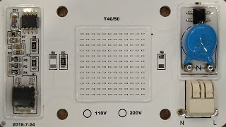
- Another requested test. Putting a 10uF 400V capacitor across the LED array on the driverless 20W LED. This required a little silicone surgery to gain access to a concealed track.
The result was actually quite good, and got rid of the real harshness of the flicker.
If you try this then it's probably a good idea to use a couple of wires to jumper from the two connection points to a cooler area for the capacitor. I'd also suggest putting a 1 Megohm discharge resistor across the cap to avoid nasty surprises. I used a 10uF 400V electrolytic capacitor and added a 10 ohm resistor in series to limit the peak current as the capacitor charges at initial power-up.
If you enjoy these videos you can help support the channel with a dollar for coffee, cookies and random gadgets for disassembly at:-
www.bigclive.com/coffee.htm  Наука
Наука


![[131] Reparaturversuche an der RGN354](http://i.ytimg.com/vi/fD5wLv5HRTE/mqdefault.jpg)


Just a random comment.. I really do like the 'zoom by printing out the photo' method. I'm fairly sure it's mostly to keep the editing down, however it looks good, gives a good feel to the channel and of course you can draw on it!
Never change it. :)
"I'll put a link over here..."
👍😀
New video from you, and photonic induction is back what a great day!!
I mean it makes sense.
I always thought he worked with electricity somehow.
Thanks Big Clive, I really enjoy watching your videos! I learn something new on almost every one.
Another brilliant, informative video, thank you Clive.
Thank you, Clive. I guess it worked rather better than I was anticipating.
This is a good solution! Thanks BC !!
This measure makes this LED usable even indoors but I would use it on outdoor and garage/workshop use. Until they (manufactures) decides to make the on-built circuit flicker free and drive the on board chips cooler.
Cheers
Well done Clive.
really enjoyed the 3 vids Clive
That was a lot of fun !
Thank you for messing about!
I hope we can see more experimentation and playing about with products like this, it's interesting, entertaining and a great learning experience.
I wonder what the correct layout would be to make a fantastic driverless LED COB like this with no flicker?
Very interesting!
Bummer about the cap getting hot as it will shorten it's life expectancy a bit, but as you say, remoting it into a corner would help.
Really cool mods!
"this is a 1W metal film resistor, *by the looks of it*" I love how you say that :P
Thank you for going across the LEDs! My first thought was the current limiting would result in lower average brightness (since it's "fixed-power" from the current limiting), but less flickering. Guess the voltage fluctuates enough to increase the consumed power and worsen the p.f. but still neat.
Well I'm glad you take the flickering serious. Many people don't seem to care much about whether lights flicker or not. Which I never really understood, it annoys the hell out of me, some low frequency PWM brightness control too. It's so annoying when have this stop motion effect whenever you quickly look somewhere else.
I've always thought it's so ironic, that LEDs which don't have to flicker due to the way they work are so often powered in a way that makes them flicker. It makes them so much less pleasent.
I do think the idea of having the driver on the LED itself rather neat though and actually wanted to try soldering a capacitor across the LEDs on one of those driverless LEDs myself. I guess you beat me to it. :-)
Another great video. Question: would multiple cobs, given a common 230v supply, flicker at a common frequency, or would the seperate drivers create multiple flickers and smooth the overall problem?
Thanks for doing that Clive, even though it proved me to be wrong. All I can say is that it shouldn't have reduced the flicker much and so in the true spirit of RUclips comments I shall continue to believe that it didn't despite all evidence to the contrary.
i like that follow up videos! great job!
I'm watching these with great interest because I am currently converting a bunch of former halogen floodlights with burnt contacts using 20W panels similar to these except 110V. Mine don't seem to flicker, though.
BTW: After seeing your power meter I found an inexpensive 110V one on eBay. It says my "20W" LEDs are consuming 23W. I can live with that considering that they will be replacing 100W bulbs.
Excellent three videos on these LEDs!
K Watt.
Thanks for revisiting this one, do you have an oscilloscope to show us any waveforms ? I was thinking of ordering one of those £16 scope kits, wonder if they re any good.
Hi BigClive, can you make a video of your work bench and the video/lighting setup?.
Hey, how did you manage to bring the power factor back up to acceptable levels as opposed to the previous experiment where you put the capacitor across the bridge rectifier?
What would the temperatures and power dissipation be like if you used thermal paste to bridge the aluminium backplate and the metal casing as opposed to bare metal on metal
Very intresting Clive not that i understand everything, i do however understand the shorting out of the cap, that one gave a nice spark and crack.
Clive, thanks for looking into this. Would a resistor along and after the capacitor placed between the bridge rectifier and before the LED's help to lower the light, the heat, and help keep the flickering reduced? It seems that the IC chips try to bring the heat down by turning the chips off and on creating some flicker to control the heat issue created by the capacitor. I would thing it would also help the LED's from being over driven when the (smoothing) capacitor is added to reduce the flickering. The makers have probably designed the led module calculating the resulting amount of LED's on time creating heat and figured the flicker would not bother anyone. When used as a street lamp, with reduced cost and complexity it would seem like a good idea.
Overall i would say that was a success. A little flicker in the vid, but to the eye i'd bet it would be hard to notice.The lower part count is attractive on those units.
Time will tell if they become popular.
My idea at flicker reduction uses no caps at all but wreaks havoc on the power factor anyway.
Noting Clive's earlier analysis on the dark voltages, the LEDs are off for a total of 120 degrees of each cycle. i.e. a third of the time!
One could reduce that dark window to a quarter of that (30 degrees) by splitting the LEDs into 4 banks that are switched from series to parallel in stages as the voltage falls, and then progressively back in series as the voltage rises. As a first stage switch from all banks in series to 2 parallel series of 2 bank each, then to all 4 banks in parallel.
The current through each bank remains approximately constant but the total current draw first doubles and then quadruples from them all in series. Hence the dreadful power factor!
If the residual flicker is still offensive, then the capacitors for smoothing need only be supplying current for the LEDs for the 30 degrees or so.
where did you get that meter, it looks pretty nice. especially since it can measure the cosinus phi (Power factor)! interesting to see this work with small incuctive loads etc
Thank you! Great inspiration. I just found your channel and immediately ordered 10pc from China.
One thing: I am an amateur, but would not a larger capacity for the capacitor reduce the drop in voltage and thus reduce the flicker? I found C = I * dT/dU on Wikipedia which would result in dU = I * dT/C and for 0.00001F, 0.1A and 0.01s (@50Hz) the resulting drop in Voltage is 100V. Is it not?
So using 100uF (if that exists?) would reduce the drop to 10V which might not be visible.
Another question: Is it possible to use a bridge rectifier and a filter capacitor *before* the whole chip -> thus feeding 325V DC on the chip and then putting two in series?
Great inspiration and looking forward getting my own China LED COB's :)
good test. seems to be the most effective application so far and not much expense to get flicker free either.
why 3 dislikes to this video ?
What if you added an appropriate inductor inline with this. Would that stabilize things a little bit better?
I wonder what would happen if you run these without heatsink. Given that you said there is SOME thermal management on that driver ICs. Can you please make a test if the chips will protect the LEDs and themselves by lowering current in case of prolonged period of running without heatsink? Thanks.
Clive, I like the style of power meter that you use, with all of the values visible at the same time. However, I have had no luck finding one for sale. Do you have a known source for that HOPI meter (it looks like a 9800)?
Thank you love these videos man I like any thing led
Thanks for all the videos BigClive.
I want to use these cheap, and easy to install light sources.
I hate flicker and can NOT stand to it, I envy the ones who don’t see or feel it.
I do not want to remove and modify the circuitry on the PCB to much (hopefully none) this defeats the idea.
I was thinking of a solution to apply a few of these in one go, or install easily on each one.
---
Many people suggested (also my first idea) ---You need a big cap connected in parallel on the bridge output for smoothing out DC supply for LED. But this alone could raise DC voltage too high for the original design. So you also need another small cap connected in serial at the input of the bridge to lower the overall voltage such that the DC is within the range of original design.
This still seems to be a simpler solution to install, with a motor run capacitor also mentioned by others. (The cap is far more expensive then the led itself, LOL)
Can we hear from people who has tested this, BigClive would you like to give it yet another test?
Ideal solution IMHO keeping the cost and complexity simplest:
If the number of LEDs increased to consume all the rectified DC voltage and a large enough Cap is attached to smooth the DC, then it would work with no flicker and no extra heat, since the drives do not have to burn all the extra power.
In a 230V example if there are 120 LEDs then that is around 300V (or maybe 100 ) across this would work on rectified DC….
Solution/suggestion 1)
Flicker is a problem how you perceive it. In an incandescent lamp we don’t feel it because the heat on the filament acts as a dampen and smooth’s the output. Above we are trying to do the same with a cap, since the led switches off instantly. How about putting a phosphorus sheet over the leds , like the florescent light or the old blue LEDs used to work?
Solution/Suggestion 2)
This is for the 230VAC world, sorry
How about rectifying the 230VAC (220~240) that is around 324VDC the connecting a same power/wattage 220VAC version and a 110VAC version in series?
The leds will have a voltage drop of around 185V + 90V and there should be no flicker. Then I can install these in gangs of two …
Any one know circuitry for LEDs in a 110V?
deleted
would adding a small cheap driver fix the flashing? would I need a driver to link more than one of these LEDs?
Clive, SlyPearTree made a good observation in his comment that the BP5132H datasheet shows a cap across the LEDs without a resistor in series.
Love watching your videos as am trying to build a grow light but I just keep getting to confused
It would be interesting to see an electronupdate-style solar cell test of the light output with and without that cap.
I would love to see a more detailed video of how to run these at lower power higher efficiency for longer life (at this price say 5w each) then I can just array them for more light.
anyway to run them in pairs so they flicker in opposition to visually remove the flicker that way? is that even possible?
I ordered the 110AC version of the 50W driverless LED modules, I was wondering, if I put a discrete bridge rectifier on the AC line, put a 10uf 400V cap (and capacitor discharge resistor) on the output of the discrete bridge rectifier, then put (2) driverless LED modules in series with the output of the discrete bridge rectifier. Would that work to reduce the flicker (60Hz here), and by splitting the voltage between the driverless LED modules (in series), keep the current down to a reasonable level and make the driverless LED modules last longer?
Interesting results. I'm wondering how the mod in your previous video would do on US mains which would be ~170VAC fully rectified. Might have to pick up one of those and a few caps and tinker with them.
It won't work at all because 170V is lower than the sum forward voltage of the series of LEDs. The LED module depends on this, so they could make a version for 110VAC market but it would have a different LED layout with half the LEDs and another of that in parallel for same wattage.
Ah you're right. I was thinking they used 54 LEDs not 74 so yeah it'd probably be a massive fail.
Great results I would say. Considering the first test I recon this would be a fair bit better for indoor growing. It's quite interesting how the flickering effects growth on plants since it's literally limiting the amount of light the plants get. No flicker would be ideal but hell, the price of these things is a bargain compared to HPS, metal halide or even just fluorescent and incandescent. If however I had the cash I would still go with the outlook that, "diversity matters most" and build an array with every one of those lights.
Can you try with a bigger capacitor in order to see if you can completely eliminate flicker? Thanks
Dear Clive ,
I'm building a 100 watt led spotlight.do you have any experience with Cree led's?...I've read the are a lot more efficient ,though they are a lot more expensive than Chinese led's.is there a brand of Chinese led that compares in quality to Cree ?.....or is the better quality/efficiency claim by Cree just an advertisers slight of hand?
I alive off grid,and power is something I try too use as little of as possible.Any advice you could give with regards to building a 100 watt led would be greatly appreciated.
Hi BigClive, have you tried silicone remover stuff, instead of harsh scrapery & diggingness?
Isn't that going to be a potential problem because you want the silicone gone on a specific area but not to damage that around and on the whole LED array?
Thanks for trying my suggestion! I've ordered some 30w ones, and will experiment with them when they arrive.
Paul Martin +BigCliveDotCom I ordered a few, too. I think it is called "The Big Clive Effect"
yep. Surprisingly, though, i've never regretted anything I bought from a BC video.
I've ordered 8 as well (different combinations of whites and wattages).
I've bought 10 120v ones. Can't wait to experiment with them!
What if you put that negative lead of the cap directly onto the chip, and stuck the resistor between that, and LEDs?
Thanks for your very educational videos! Can you tell me if your meter came equipped with USB port (at the top side, that we can't see)? I'm looking to purchase this, but I would like to have the USB port.
It's got a hole for the connector, but no connector.
Can you try to find out, wich capacitance you need in order to make it not flickering to the camera? And i also got an question: to wich temperatur is it safe for LEDs to work on? Because i have an flashlight that reaches (led) temperatures of 90°C
Hi, I have a similar COB module, 20W. I tried to place a capacitor plus resistor as suggested and the flickering improved slightly. I the used Viso Flicker tester (no affiliation) to use my phone as light meter. I noticed the following (I cannot load photos herein the comments): the module without modification gives no light until the LEDs begin to conduct (72 LEDs in my module), then the light output rises sharply and then stays constant, until the sharp fall and then no light until the next cycle.
With the capacitor and resistor added as you suggested, the rise of the light output is slightly slower (the capacitor steals current to the LEDs), but the decrease at the end of the cycle is much softer. However, the power at the plug is the same, because of the constant current driver is placed BEFORE the added capacitor and resistor (like in your case).
I would be interested in seeing the same measurement on your module before and after modificatio. The app is free anyway...
Thanks
Was there heatsink compound coupling the aluminum backing to the larger mass of the case? Would that matter for the temperature issues?
It would matter, it's the same with a CPU and its cooler.
images.bit-tech.net/content_images/2009/02/all-about-tim/compound.jpg
Is 10uf enough to stabalize 100ma especially with the cycle having to go through a 10ohm resistor?
Hi, I was getting a flicker using 120VAC LED modules on 120VAC, when they warmed up, they seem to work fine, the flicker is annoying. I tried the 10uf cap and bridge rectifier (120VAC IN, 170VDC OUT) it would light one LED module (too much current), but not two in series (barely glowing LEDs). I am using the 50W 120VAC LED modules. I am not opposed to a lower output, if it means greater life. Any quick fix ideas?
great mod!
You can feed them with DC as well, but at what voltage that will be?
I donno if it's my eyes, but i feel that the camera is higher quality with the higher exposure setting for the last 1/3rd of the video.
There's a point here I am unsure if has been covered.
The original datasheet for the BP5132h states it can be dimmed using triac type dimmers.
Looking at the original circuit we see how they feed Drain1 with a resistor and seperate the capacitor they have on Drain2 from that with a diode.
CS1 is also experiencing the two resistors they drew in series while to ground while CS2 only experiences one. I am thinking both these are linked to the dimming aspect of the driver.
It wouldn't be the first time chinese are a bit lax with the naming and labelling. I think the schematic show how it works more than the names do.
It unfortunately also states that it starts to work from 12v and up so it may be that they simply time multiplex the current and thus allow a sort of dimming.
I'd love to see some tests on these with dimming, just to see what it will actually do.
If I had em here I'd also film it with my cam set to 600fps to see what is actually happening with dimming...
This still flickers rather badly. With the first method the camera barely could see any shimmer.
What size capacitor would you need in this place to reduce the flicker to the same degree? Maybe a 100µF one?
So is there any difference in lm/W? aka does it make sense to a)save power b)get more light out of same LED
If my memory serves me right, didn't the schematic on the regulating chips datasheet have a capacitor in parallel with the LEDs but without a resistor? I'm to lazy to go check.
Good memory! Yes the BP5132H, and possibly the other two (I don't recall) has an NP capacitor across the LEDs with no resistor. Due to the cost of one 10uF & 400V, I imagine they had a smaller capacitance value in mind, considering two of the primary points made in the datasheet description were "a quite small BOM benefit from no ECAP... ". 400V 10uF film cap doesn't fit in a "quite small BOM".
would a larger capacitor make the flicker even less noticeable? i'm considering in making a "god light" from a few of these
Given the relatively low cost [even at 500+ we are looking at 30p or so] of electrolytic capacitors and the apparently extremely simple nature of the circuit this technology seems promising for general purpose use. One question though - if you were putting a capacitor across the rectifier at the design stage wouldn't you simply put more LEDs in series to take advantage of the higher presented voltage without overloading the chips?
why 10uF? would a higher (say 100uF) give better flicker reduction or is it asking for trouble ? :)
Hi I have found some of these led chips I like but they only have 220v ac. Would the light on 120v ac but dimmer / less wattage?
They may not light at all.
Is it not possible to use a large inductor in series to smooth the voltage?
I was wondering that myself. Some of the comments in the earlier videos seemed to indicate that's what some folks were doing. It seems to me that if a capacitor after the bridge rectifier (or after an external bridge rectifier) boosts the voltage too high, then perhaps an inductor filter might be the way to go.
Clive, you suggested putting a capacitor in series with AC input, creating a capacitor dropper circuit. Have you tried that yet?
I've not tried that yet, but it would be best suited to very low power use like 5W.
not to give you any "bad" ideas, but what would happen if you put a capacitive dropper on a 50W+ load? if such a thing would make the device more exiting you should make a video about it. for general knowledge ofcourse, not that everyone want to see caps exploding....
Would you recommend a bleed resistor (multiple for the high voltage) across the new cap?
good idea, perhaps one or more Meg, though the light will be hard-wired in, so no probs with plug pins and hands,
A 1 Megohm quarter watt should be OK. Or two 470K in series.
Not sure if already said but I suspect that these devices are so cheap is because at the Philips-China test track where such may be tested in street lights the number of accidents blamed on flicker was too large. I was told that the Boots escalator in Aberdeen is a fainting zone for people who cannot handle the combination of flicker of lamps and old juddery stairs. I did try it a few times and I could see how disorienting such flicker was
Your awesome love the videos
Dramatic reduction in flicker without the dramatic reduction in power factor like the previous experiment.
Instead of adding the 10R resistor in series with the capacitor, the 0R link on the mains input side of the bridge rectifier could be replaced with a suitable resistor and let that help limit the inrush current. Use a 105 degrees rated electrolytic to maximise its life.
now u have removed flick next vid introducing strobe ?
Clive, I have a question about power factor (not of these LEDs, but more in general): A couple of weeks ago or so, some Dutch researchers publicized their tests with the new so-called "smart" power meters (we in Germany still mostly have the old electromechanical or "Ferraris" meters, but the EU wants to press electronic meters upon us in a few years). According to the Dutch scientists, those meters that use a Rogowski coil as a measuring device, measure too much power, while those that use a hall sensor measure too little. How relevant is this going to be for us (not for you though, since Britain is leaving the EU), having lots of cheap-ish switch-mode power supplies, capacitive droppers, LEDs and so on connected to our mains wiring? And what can we do against it, except hoping the meter that is going to be installed will use a hall sensor? It would be an interesting topic for a video! Especially now since we (in the EU) all have to dread getting an electronic power meter... Here's the link to the PDF: storage.googleapis.com/files.dinside.no/9/maalere_rapport.pdf
such capacitatiousness
Bloody interesting chips those. Like yourself I really hope they don't become mainstream. Imagine flickering street lights for starters..
Is this LED dimmable from the mains without damaging the LED module?
Yes it should be, but may have an odd dimming curve.
Really interesting. To bad it flickers so much.
I'd say the cap on the bridge is the best result or at least for almost no flicker on the camera any how.
This one was still not bad but still a small flicker.
hmm... this was my idea as well where the capacitor should go. However, that 10ohm looks a bit big to me.
For bicycle, I used three capacitors with higher capacitance to smooth the flickering... just to find out that two Cree XP-G is totally fine without any resistor on a hub dynamo, and also will eat up the capacitors charge in an instant, so no light for me when I stop :D
big clive what electrical wire is too thin to be used for a 240v device. i have a old electric alarm clock that I'm concerned the wire is speaker wire ?
+Nateyboy1990 Many old clocks used something that looks like speaker wire. The main requirement for mains wiring with such a low load is the insulation. If in doubt you could change the cable for a modern one.
yeah I'm looking for modern wire just hard to find online should have a look in bunnings (australian hardware chain have recently emerged in St Albans hertfordshire) be simple to do i have changed a uk plug for a australian plug before cannot be that hard.
I like the "RUclips make it better" thing with follow up vids..
Putt a two capacitor, one is with resistor positive side and other is negative side resistor :D DC 50Hz filter need another wey. What is ferrite core coil inductor ? :)
Can u may pls make measures with an oscilloscope? That would be awesome !
Love ur videos :)
@bigclive have you ever done the teardown of a LED filament lamp, the type where the filament look flexible, I wonder how the filament is made because all the filament we can find are made of glass/ceramic
The first filaments I took apart were a metal strip and could be bent in one direction.
Oh ok, the filament I can find actually have a ceramic or glass substrate that break as soon as you are slightly trying to bend them :/
I wonder how are made this sort of filaments: www.peterreidlighting.co.uk/media/catalog/product/cache/1/small_image/400x/9df78eab33525d08d6e5fb8d27136e95/c/i/civilight_u_squirrel_cage_led_cutout_screw_1_1.jpg
dear .. what is best 20 watt led
Can inductors be used as a means of preventing inrush current instead of resistors, since they resist changes in current flow?
yes, chokes do that, the mathematics are a minefield,
30 odd years ago when in training for electrical engineering I didn't quite know why chokes were there, then later it 'twigged', ahh, yes, back EMF and all that, fascinating stuff. J.
one last idea: capacitor in parallel to the rectifiers output and a choke in series with the input?
One more! increase the value of the sense resistors to lower the current. Also, remove or lower the 10 ohm resistor on the cap, with a bit of luck it will give the led a softstart.
Sigh, we're down to redesigning Chinese LEDs to make them more reliable. Oh wait, we passed that point already.
or an NTC thermistor instead of the resistor, OR considering the low price of these LED modules, just try it without the resistor and see what happens, especially now that we know with one there. However I'm wondering if the capacitor temperature is really the result of the vicinity to the LEDs, or its ESR? Has Clive measured the driver output frequency? I must admit that I wasn't paying enough attention to notice how this driver worked, whether it stays at 50Hz or higher. If at 50Hz, I wouldn't expect ESR to be much of a factor.
An inductor in series with a capacitor is a tuned circuit - specifically, a bandpass filter. There will be a narrow range of frequencies that will experience very low resistance - and that range of frequencies will be part of the 'square-wave' power-on signal
Can someone advice me which color temperature is better on these type of chinese 220V COB LEDs, warm or cool white? Generally I prefer warmer light, but I saw some videos and pictures showing both light colors outside and the warm one seemed very orange/brownish and low CRI...
Can someone help me with this one? Cheers
If you're in a cooler "Northern" climate, warm white is more agreeable to most people. They look yellowish in pictures because of color correction and display color error, but _usually_ aren't nearly as yellow in real life. I used to prefer 'daylight' color CFLs and LEDs, usually > 4,200 K, but those look quite blue to me now, so I only use 3,000 - 3,500 K. If you prefer warmer light, that's the way to go. :)
Try taking a picture of a light source that's labeled warm-white yourself, and then look at the results on whatever device you've been using -- note that you will get different results with different color and exposure settings.
could these leds run on stable dc?
The last test showed there was no flicker then became unstable, something must have became compromised and weakened so I would start off fresh with a new one. Here we are adding a capacitor then a resistor on a rail with no isolation. I don't get it?
Shouldn't we have to make a break in the rail then surface mount the parts between the two breaks? Allowing the capacitor to bridge the connection then the same for the resistor?
So my LEDs arrived today. I ordered 2x20, 30 and 50W each in CW and WW. The 50W version is looks significantly different (only 72 LED chips and clear "goo" on the driver chips).
But the main question is now: where do I get suitable heatsinks?
You can use aluminium channel from metal stockholders or buy actual finned heatsinks from eBay. (Or just retrofit then in similarly rated floodlights.)
Heatsinks that cost ten times as much as the LEDs themselves XD . I wonder at what temperature the lifespan is reduced to one tenth of the advertised 10,000 hours. Something to gamble with. Thousand hours is around 40 days, that's almost in the realm of being able to test it and have the LEDs still available to buy after that.
try looking for used PC coolers, you should get them pretty cheap ;)
Why is it 50 or 60 Hz? Why not 50 kHz or 1 MHz? Is this something to do with the power plant generators rpm or what?
You know I might actually ramp up the capacitance a bit on this one and whack in another 10uf cap in parallel. Of course being in the states the normal current around here is 120vac which might reduce the strain on the chips enough that it would work pretty well with on of those particular LEDs.
At 170VDC, on the output of the 10uf cap and bridge rectifier, I am already at peak voltage (120 X 1.414 = about 170). So increasing the cap, should have no effect. Putting 170VDC on a single 120V LED Module is going to be life shortning, because of the heat dissipation.
Oops, didn't read the time stamp, I thought the reply was for me, sorry...
What if you were to run with the capacitor across the rectifier (like in the previous video), but run it on 120V?
Won't work, input voltage to series of LEDs would be below the sum forward voltage of that series of LEDs.
Stinky Cheese
Yeah. I was doing that arithmetic after the last video trying to work out if you could bodge a 2nd unit in series some how but figured you'd need to break the 2nd unit and solder part way along the chain.
Stinky Cheese ah so the capacitor can only boost voltage from rms to the peak?
Clive I have a question (not related to this video).
Recently we had an electrician around to look over all the electrics in the house and he found that one of the sockets in my bedroom had the Live and Neutral connected the wrong way round. I was just wondering if that could have caused any problems or doesn't it really matter? (standard U.K. Socket)
Wel, i'm not Clive but I can answer your question. It shouldn't have caused any problems since here in europe where I live you can plug the plug the way you want, and devices don't care if neutral and live are swapped since it's AC, so theoretically it shouldnt, but lets see if an engineer can answer this question better for america or where you live.
It would have meant that in the event of a neutral (live) to earth fault in an appliance the fuse in the plug would not have blown as it was effectively on the Neutral. That means the appliance would be protected by a 32A breaker. Other than that most appliances would have worked fine.
I'm not Clive either but, no, not really, unless you plug in something like a toaster where the elements are normally neutral, (and exposed) if you plug in said toaster and poke around in it when it is 'off' everything inside is very'on', Sorry about the bad explanation, J.
Worse than that, it meant that if the fuse failed open circuit for any reason the appliance would appear to be off but internally would actually be connected to live.
what he said.
To reduce the flicker even more, you will need a bigger capacitor.
check out one of the bigger 100w grow led lights :)
Would someone explain/suggest a modification to my current experiment? (Sorry for being out of place)
I've been messing around with capacitive dropper circuits, I'm powering one 0.5W led at 60ish milliamps.. I've sorted out inrush current and the like, but something is rather puzzling to me..
My plug in power meter shows a current draw of 60mA, a power draw of 13-14W but (here's the catch) a power factor of 1.00
I thought that capacitive droppers would always have a significant power factor impact especially with such a small load.. Is it just my power meter that's giving me false results or is there something blatantly obvious that I'm missing?
IIRC the cheaper ones can be inaccurate at calculating PF at low current... I think Julian Ilett did a vid about it.
if you've got a scope you could have a go at working out the angle between voltage and current, the PF is the cosine of that angle
PF isn't really something to worry the domestic user - would be more of an issue for industrial lighting or council street lighting which I guess is why BC gives it greater prominence when he's looking at these more industrial units.
Thanks for the reply, I do have a scope so I'll look into it later in the week. Here in Ireland PF isn't just limited to industry, even with a significant phase lag the mains input power meter (in my house at least) will show the same power draw even if the real power being drawn is lower.. We don't have to pay more for reactive power like industry but it's worth keeping in mind that it still goes towards a bigger bill
yay said it would work :)
try a higher value cap. that might reduce the flicker ... more energy