And happy New Year Charlie ,you have been busy there and watching with interest also as i have been playing round also with the BD139 RFamp before xmas for a homebrew ssb rig ,but i had a spurious i was also amplifying but got that fixed as my BPF needed rebuild so have taken notes from ur videos ,which with ur experiments with the BD139s have been helpful.
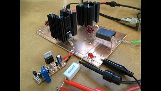
Very interesting series Charlie, 10 to 15 watts from BD139s, worth knowing, they make good drivers so interesting to see them used in a PA. In summary the circuit doesn't seem too sensitive to the transformer ratios, and the power dropping off above 10mhz like the IRF510s helps to make it stable at lower HF. You've answered all my questions, what's next?
Hi Paul. Not sure what to do next. I'm currently working through some noise issues after reconfiguring the current rig, which I want to fix . I also want to rebuild one of the SSB tramping rigs too before the next tramp. So many things to do and not enough time!
@@CharlieMorrisZL2CTM Are you interested at all in AM? We have an 11am AM net on 160 here, and it motivates a few homebrew projects. I've built a few AM superhet receivers, they present a different set of design challenges. Another reliable AM signal source is WWVH. Hang on, is that still there or did the US govt shut it down? Oh well. Theres always BC band. Oh, I think I heard Europe is turning its MW AM stations off 😖 A good AM detector is not a simple thing. Not just a diode! Have a look at the one in G6LBQs Irwell transceiver. This Anyway just a suggestion. I'll watch your vids whatever you do. de VK3HN.
Andrew Ferg I got 160mW output from two PN2222A transistors connected in parallel. Output frequency was 99MHz. It's a 2n3904 and PN2222A based FMTX. Would you like the schematic? The transmitter is quite stable as the oscillator is driving the amplifier chain via a 4.7K resistor.
Great ! could you try it with binocular core (made using T37-6 and glued together). Use tri-filar wound transformers. I believe with 13.6 volts input supply, the ouput should go around 8 - 10 watts.
Hi Charlie, this has been a fantastic series - thank you! I had a go at creating an ltspice simulation (you can access it here: cloudstor.aarnet.edu.au/plus/s/E4enKO4t6APOWUs ). I think it correlates quite well with what you've built (at 7 MHz). I had a play with the input and output turns ratio and settled on what's there. About 6 watts from 13.8 volts at 7MHz. Running at 24 volts gives us about 10 watts - not sure if that's realistic. At 28MHz and 24 volts it's about 1.5 watts. Anyway it's there if anyone wants to play. Cheers, Ian


I like it ! Lots more wattage that I was thinking it could put out .
And no magic smoke was released!
And happy New Year Charlie ,you have been busy there and watching with interest also as i have been playing round also with the BD139 RFamp before xmas for a homebrew ssb rig ,but i had a spurious i was also amplifying but got that fixed as my BPF needed rebuild so have taken notes from ur videos ,which with ur experiments with the BD139s have been helpful.
That's great that you got your amp going. Hopefully, you wont be too far away from getting the whole rig completed.
Charlie
Very interesting series Charlie, 10 to 15 watts from BD139s, worth knowing, they make good drivers so interesting to see them used in a PA. In summary the circuit doesn't seem too sensitive to the transformer ratios, and the power dropping off above 10mhz like the IRF510s helps to make it stable at lower HF. You've answered all my questions, what's next?
Hi Paul. Not sure what to do next. I'm currently working through some noise issues after reconfiguring the current rig, which I want to fix . I also want to rebuild one of the SSB tramping rigs too before the next tramp. So many things to do and not enough time!
@@CharlieMorrisZL2CTM Are you interested at all in AM? We have an 11am AM net on 160 here, and it motivates a few homebrew projects. I've built a few AM superhet receivers, they present a different set of design challenges. Another reliable AM signal source is WWVH. Hang on, is that still there or did the US govt shut it down? Oh well. Theres always BC band. Oh, I think I heard Europe is turning its MW AM stations off 😖 A good AM detector is not a simple thing. Not just a diode! Have a look at the one in G6LBQs Irwell transceiver. This Anyway just a suggestion. I'll watch your vids whatever you do. de VK3HN.
Great setup! Thanks for sharing. Just curious if you have experimented with a push-pull arrangement in the 100MHz broadcast range?
No I have't Andrew. My interest is in the lower part of the HF band.
Andrew Ferg I got 160mW output from two PN2222A transistors connected in parallel. Output frequency was 99MHz. It's a 2n3904 and PN2222A based FMTX. Would you like the schematic? The transmitter is quite stable as the oscillator is driving the amplifier chain via a 4.7K resistor.
Great ! could you try it with binocular core (made using T37-6 and glued together). Use tri-filar wound transformers. I believe with 13.6 volts input supply, the ouput should go around 8 - 10 watts.
Hi. I'll add that to the list of things to look at when I dig this amp back out again.
@@CharlieMorrisZL2CTM thanks
please make a push pull rf amplifier using 2sc2630 or 2sc2694 or 2sc2782 or 2sc2237. thank you
please make the fm rf push pull amplifier that cover from 87.5-108mhz fm band. thank you. and please share with us including the circuit diagram
Hi Jerome. I'll add that to the list of ideas for future builds.
Hi Charlie, this has been a fantastic series - thank you! I had a go at creating an ltspice simulation (you can access it here: cloudstor.aarnet.edu.au/plus/s/E4enKO4t6APOWUs ). I think it correlates quite well with what you've built (at 7 MHz). I had a play with the input and output turns ratio and settled on what's there. About 6 watts from 13.8 volts at 7MHz. Running at 24 volts gives us about 10 watts - not sure if that's realistic. At 28MHz and 24 volts it's about 1.5 watts. Anyway it's there if anyone wants to play.
Cheers, Ian