DSO 138 DIY Oscilloscope | Calibration | Cheap Oscilloscope | Color screen | DSO Manual

HTML-код
- Опубликовано: 5 сен 2024
- DSO 138 DIY Oscilloscope | Calibration | Cheap Oscilloscope | Color screen
With probe.
DSO manual can be seen at the end of video.
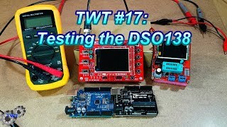
This DSO138 digital oscilloscope kit adopts ARM Cortex-M3 processor and with 2.4-inch TFT screen. It's easy and reliable for circuit operation. It can display frequency, period, pulse width, duty ratio, MAX./MIN./AVG./Peak-Peak/virtual values.
Features:
This kit uses ARM Cortex-M3 processor (STM32F103C8), and includes a 2.4-inch color TFT display screen, can be used as ARM test development board.
Can be secondary development on the basis of this kit, for example, it can be changed to Millivoltmeter, data loggers.
Adjustable vertical displacement, and with instructions.
With automatic, regular and one-shot modes, easy to capture the moment waveform.
Available rising or falling edge trigger.
Observable previous trigger waveform (negative delay).
Can freeze at any time waveform display (HOLD function).
Comes 1Hz /3.3V square wave test signal source.
With waveform parameter digital display, including frequency, period, pulse width, duty ratio, MAX./MIN./AVG./Peak-Peak/virtual values.
Waveform storage function: will not lose the waveform after power off.
Short-circuit and open-circuit detection: can help the user find out the soldering error.
TFT controller recognition function.
Specifications:
Maximum Real-time Sampling Rate: 1Msps
Accuracy: 12Bit
Sampling Buffer Depth: 1024 bytes
Analog Bandwidth: 0-200KHz
Vertical Sensitivity: 10mV / Div - 5V / Div (1-2-5 progressive manner)
Input Impedance: 1MΩ
Maximum Input Voltage: 50Vpp (1: 1 probe), 400Vpp (10: 1 probe)
Coupling Modes: DC / AC / GND
The Horizontal Time Base Range: 10μs / Div - 50s / Div (1-2-5 progressive manner)
Supply Voltage: DC 9V


10:10 Calibration
Very Nice Explanation Sir Thank u
my calibration was similar... adjusting the capacitors had no effect... did you ever learn more about this? or the analog gain calibration?
Just curious why are you wearing hazardous waste gloves?
Lol they have got good grip
1. Hissing/ beep sound coming from the device.
2. Test rectangle signal is not flat at peaks (I am using 9v supply from buck module).
Any help ? :)
Ya may be you are using buck module. Buck or boost modules run on pulses and can produce noises very easily. May be try some more stable supply. Hissing sound can be made either by inductors or beepers.. I dont think this device has anything else that can make sound. Inductors make sound when on high load and operate at audible freqs.. thats also strange in this case as this is low power device!
@@ProDroneControl bigg thanks for your response. :) Any alternate?
Out put voltage ?
did not get the question ..
No sound so idiet vedio