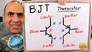
How a Transistor Works EASY! - Electronics Basics 22 (Updated)

HTML-код
- Опубликовано: 17 сен 2016
- Let's take a look at the basics of transistors! Try the circuit!: goo.gl/Fa8FYL
If you would like to support me to keep Simply Electronics going, you can become a Patron at / simplyelectronics  Наука
Наука


Something good to remember 0.7 v is the minimum voltage required to turn on a transistor
0.7 is for forwad baisin in silicon ,
Not compulsary
For germanium it's 0.3!!
@some1mn N nope it's 0.3 google it!
@some1mn N yes, some teach .6 volts and some teach .7 volts... Either is correct 😊
It depends on the physical transistor as the turn on voltage varies based on the physical construction
Also at the edge of saturation vbe=0.7v and Vce=0.3v for npn.
0:41 Note: _solid state_ here means with _no moving parts,_ that is, no human intervention is needed to toogle the switch (the transistor.)
Watched 3 videos on why transistors were so important and how they worked and didn't come away with anything useful.
Watched two minutes of this video and understood exactly.
Same
Honest Insincerity 2 Exactly the same over here bro. I thank God for this video
Look up videos on the water analogy
This is my third video also. The first one was the Bell Labs video. Was pretty good too. Need to revisit that one. It has some names I want to write down and research. This one has very good animation.
You see these comments on every engineering video on RUclips. Apparently it's the individual and not the lesson.
Nice explanation. Im glad someone is actually putting things into laymans terms. Thats basically the same way i learned about transistors, Except in my case i learned it was basically a miniturised version of a relay used in general automotive applications.
I am an absolute amateur with electronics, but this video his on the head a little side project I'm working on: controlling an LED strip with a microcontroller using PWM, something I was kind of considering necessary but not sure how to do. This makes it way more clear. Great video!!
2:50 I’ve watched so many videos and never understood transistors, and these 30 seconds explained it to me better than anyone else ever could (I’ve worded this comment funny, haven’t I?)
Mr Awesome
Yes. I still don't understand. Maybe I should just watch other tutorial videos first before I spend my time repeating this one until I understand it.. Maybe the problem is the video and not me being unable to understand it.
I @@johnlamarca9439
@@johnlamarca9439 the
@@johnlamarca9439 to
this is the best explanation of transistors I've seen on RUclips.
Thank God. An easy Explanation !! Much Thanks.
I have watched up to 10 videos to unserstand transistor and this is the only one that solved my problem. Bravo mon ami . vous etes formidable.
Loving your channel man. These videos are excellent. Also, you have a really good voice. Extremely clear and articulate
I don't know if you're still reading comments to your videos, but your videos are excellent and easy to follow for people new to electronics.
This was such a to the point, concise, easy to follow and easy to understand explanation!! Thank you!
Oh mahhhh gaasssshhh💥💥❤❤❤❤❤❤❤❤❤❤❤i love youu so much!!!!! Have my physics exam tomorrow and I've studied and have understood all concepts in the syllabus except electronics MAINLY TRANSISTORS. Now I've finally understood through this explanation!.....YOU ARE A LEGEND!!!!❤❤❤❤
These tutorials are very helpful. I will review and repeat reviewing until I absorb the information. I am grateful and I thank you.
james solarz
Yes. I'm trying to learn this too. I will have to repeat this at least twenty times. But I suspect certain things were left out of this explanation of what a transistor is and how it works. I'll eventually learn it. If not from this video source then from a better tutorial I will find....
Great video! I love the way you explain things so everyone can understand and enjoy electronics, tho if we have transistors why use relays?
Watched two minutes of this video and understood perfectly!
A Good and simple explanation of how a switching Transistor works. Thank you
Comment 345 A good teacher is one who makes a complicated and difficult concept simple for the student. Obviously you are one, Best Wishes from Singapore.
Best explanation of a transistors I have ever heard . Thank you.
This is probably the best explanation I've seen so far. Thank you!
Check out Steel Wheels Downs, two practical videos on transistors!
This is the best explanation I have ever seen about transistors
Finally some good explanation how transistors work!
thank you for your episode 22, it very clear to understand. can you tell us which component used for on and off the LED and the link episode used.
many thanks.
Where do I find the Symbol to utilize Logic Level Voltage to the circuit? I love your videos, but I'm stuck on this one. Help! Thanks!
Really enjoyed all these videos, more please!
I finally get it. Sounds like the same operation of an old school control relay activated by applying voltage to the coil thus operating the relay contacts into the desired state to either pass or restrict current flow.
which tts speech synthesizer did you use to make this?
I didn't have facility during my college days.Thanks for easily understanding video's.
Didn't understand transistors until this video. Thank you!
This is very clear and high skilled explanation. You can’t find in most of the higher education colleges. Thanks sir, but I have a question about voltage level being applied directly to base of a transistor without voltage divider. I thought only a voltage of about 0.7 volts can be applied directly to base. Now in the above circuit we have 3.3V, is that level to high and can damage the transistor junction?
Very well explained.... Keep up the good work... Spread knowledge.
From 2:00 even the simulation shows no current from Collector to Emitter and nor should there be. The LED is just in series between the two cells. Circuit at 2:35 fixes this.
The first diagram shows current flowing out of the transistor collector back to the 3.3v power supply and out of the emitter to the 3v power supply but in the video it says that the current goes from the led through the transistor back to the 3v power supply. I thought when the transistor is turned on that current only goes one way through it? The way it’s drawn out in the second diagram makes sense to me but the first one has me confused...can anyone help me understand a little more please?
Really good easy to follow explanation, I tried wikipedia first, but as usual it was rather opaque.
Where did you get the digitally controlled voltage source? I don't see it on the premium toolbar.
Brilliant, if only it was explained like this for me in college!!!
Sir please reply how the current flow in the circuit determined.Couldnt understand please help..
Sir what is the transistor number that you used in the circuit?
The circuit animations are fantastic.
Hopefully I can pass my 400 level advanced circuits final next week at MIT since I watched this video now, wish me luck
Update?
thanks for this video...simply taught and catchy too!!!
Nice clean explanations. Subscribed.
Thanks a lot for the informative video. What is the name of the computer program you are using to demonstrate the circuit?
Very good illustration of transistors
I like how you explain things. Thank you
Transistors and chips are relevant for making switch-possibilities in a computer. Thanks for the explanation
You are awesome... I wish I discovered your videos since
Why is rhe bade sometimes calked gate, is this yet another example of uk vs us englusg or is it just ibconsistant naming for other reasond
which program do you use for drawing the circuits
You make it look too easy. Great stuff bro u r awesome!
Hi! Please, could you tell us which transistor should be installed to use only 01 battery increasing 1.5V to 5V to work an active buzzer 5Volts? Good video - easy to understand. Tnx :)
Kindly Can you Say What is the this software simualtor that you use?
What software do you use to simulate your circuits? I love the way you use it! It makes it easy to visualize what is happening at the atomic level.
Everycircuit.com
I have spent months researching into circuits and found an awesome website at Gregs Electro Blog (google it if you are interested)
Hello, you might get this question very many times so I'd suggest putting that source you mentioned, in the description so that you won't get that question asked on everyone of your future videos.
Every circuit
It's not a software
It's just an app
It costs £15 tho that’s the only problem.
Great content !!! I've subscribed
simply great tutorial, thanks.
How does it work as a high speed switch....pls reply
thank u so much....best teacher alive
Sir hearty thanks for this channel. please keep more videos related to electronics.
thank you , nicely explained !
hi What's the name of that software your using?
Thansk , much appreciated its simple and very easy to understand
Hi Sir, how can I use a NPN Transistor(D882) as a on off switch very fast?
How come in other's video, the power from the battery flow from the negative side?
Very educational!!! Thank You
Thanks...how can you test if a transistor is okay or faulty?
How can a small 3.3v supply a 12v? It just can?
Or it could turn on the path to the higher voltage because the 0.7 is psssed?
Or there's no explanation?(mostly in our school there's no explanation as to why these components work)
I'm trying to figure out a circuit that turns on a motor when the light input to one LDR is greater than that to another. And turns off the motor when the light input to each is the same and turns on the motor in reverse when it is the second LDR receiving the most light. If I can make two of these circuits I can design a device that angles a solar panel towards the sun. I saw a crude solar tracker someone made using small solar driven motors that simply fought one another, the motor receiving the most light to its panel winning the tug of war, until both motors stalled out when the device was pointed at the sun. I was curious to design one using transistors though.
Great video I just liked and subscribed.
Question I have is within the video and working diagram at about a 1:45 min mark, the diagram is showing the current flowing away from the collector. Is this how the top 3.3V circuit is completed? I am not following/understanding the visual motion here. I would have thought that the current would go into the collector and then out through the emitter. Is this not the case?
It also seems odd that the direction the simulation emulates the current , I was always taught that, contrary to what you would think, current/electrons travel from Negative to Positive.
FENATECH I noticed this as well, seemed conflicting to how other videos showed a similar animation.
this series taught me more than what half a semester of 3 hour classes could teach me.
www.cburch.com/logisim/
ruclips.net/user/results?search_query=logisim+transistor
Its a great and cool explanation 🙂
It's a bit unfortunate you did not clarify that this example is using a BJT, which is an analog current-controlled device, NOT digital voltage controlled as you implied in the video.
It seems you were explaining the usefulness and operation of a JFET but using a BJT in the example. It would have been nice to touch on the differences between them since transistors range in their operation and are not all alike.
I usually use Falstad for circuit simulation, so I'm guessing perhaps EveryCircuit doesn't have the same options, but it would've been nice to at least make that clarification in the video.
Clearly explained. Thanks
Solid state switches, who knew. Great explanation!
What a fantastic little invention.
I hope i could find these videos when I was doing my engineering degree 15 years ago. Then, I won't end up hating this subjects after all these years. Just there were no one could explain to me how a transistor works and that made me losing the interest on the subject.
Amazing video, thank you
thanks !
in some video it is shown current flows from negetive to positive and in some from positive to negative plz clear in which direction its flow
Very good.thank you for the information..
Which is the software you using to make circuits on computer
very educative thank you regards,
Very well explained
These are great tutorials.
What is the software in this video? Could anyone tell me? thanks
Cant we use a one power source to power both transistor and LED. ? Use one wire with a resistor to power transistor and one wire to power led or motor?
Yes.
GREAT VIDEO!
What do the squiggly purple curves represent?
where can i download that electronic components simulator?
Ji Di
Man. Just take a snapshot of it. Pause the video if you have to.
Why do you have a separate power source as well as power from the led circuit to the base of the transistor?
I could have a separate power source or the same power source supplying the base. I chose to use a separate power source to make it easier to understand as you can easily see that there is another source powering the base.
Is this explanation works for both npn and pnp transistor?
please let me know.
Im so confused.
Learn easily the basic concept of Transistor and Full wave and Half wave rectifier from the video link given bellow
ruclips.net/video/KIBHW1jRBsA/видео.html
What software is this simulation on?
awesome tutorial
1:46 your video circuit coonects the base with collector, it's wrong.
Really like what you are able to show your audience. But it should be mentioned that current flow is from negative to positive.
Dude, I was thinking the same thing. That's like one of the first things I learned about electricity.
By convention, "current" is said to flow from positive to negative even though electron flow is in the opposite direction.
Enjoyed the video.
something that has caused me so much grief, now in 10 minutes, voila! Thx
One thing confusing for me is that some of these videos show the electron flow and some show conventional flow for demonstrating the direction of the current in the circuit. It seems this video is backwards, it shows current moving from positive to negative, when in reality the electrons move from negative to positive, which can be observed in other videos from this channel. Its making it a bit harder to conceptualize trying to reverse it in my head.
In 5 minutes you taught me 5 years of schooling. Thank you I subscribed
Thank you!
sir, could you please tell me the of the software you are using in the video for making these interactive circuits.
I would like to know too
@@sonic-dna7742 /vickas sharma,
it's called " everycircuit " you can buy it on google play for like $10 bucks. also If you get it I reccomend " electrodroid plus " also about $10 bucks. but comes with an abundance of useful tools. bolth apps can be a pain in the ass and confusing at times, basic circuit knowledge is a must for dealing with either
Thanks for the video but I think I'm getting confused. In one of your previous videos on DC circuit about how electrons flow, you stated it flows from from the negative through the load to the positive. But going a bit off the transistor topic on this video, you state current flowing from the positive through the load to the negative. Can you please shed some light on the directional flow of current and electrons in a DC circuit please?
For electricans the flow goes from pos to ground. that has something to do with the magnetic field lines if i remember correct. But for scientist it follows the real flow of the electrons which is from gnd to pos.
But yea for every normal person electricity flows from pos to ground.