Pimp my Potentiometer -CHEAPER-

Поделиться
HTML-код
  • Опубликовано: 29 янв 2024
  • Do you like the video? Please consider buying me a coffee, thank you! www.buymeacoffee.com/upir
    PCBWay: www.pcbway.com/setinvite.aspx...
    Source Files: github.com/upiir/diy_led_ring...
    Source Files on PCBWay: www.pcbway.com/project/sharep...
    -----------------------------------------------------
    Links from the video:
    - 10K Potentiometer: s.click.aliexpress.com/e/_Dk1...
    - Solid Aluminium Knob: s.click.aliexpress.com/e/_DFP...
    - Breadboard wires: s.click.aliexpress.com/e/_Dkb...
    - Arduino UNO: s.click.aliexpress.com/e/_AXDw1h
    - Arduino breadboard prototyping shield: s.click.aliexpress.com/e/_ApbCwx
    - MHP50-A5 Mini Hot Plate Preheater: pcbway.com/s/AxyVVH
    - ESD stainless steel Tweezers for PCB: pcbway.com/s/8B8WMI
    - SMD LED 0402 reel: s.click.aliexpress.com/e/_DCE...
    - Soldering Iron: pcbway.com/s/OPjIMv
    - LED ring light: s.click.aliexpress.com/e/_Dmv...
    - MAX7219 module: s.click.aliexpress.com/e/_DkX...
    - Round hole pin header: s.click.aliexpress.com/e/_DkU...
    Other Videos with potentiometers:
    - Pimp my potentiometer (part 1): • Pimp My Potentiometer!
    - Pimp My Potentiometer (again): • Pimp My Potentiometer ...
    - Arduino OLED 3D Compass: • Arduino OLED 3D Compass
    - Your 1st CNC-ed Part: • Your 1st CNC-ed Part
    - My First CNCed part --EVER--: • My First CNCed part --...
    - DIY Volume Control: • DIY Volume Control
    - My First PCB --EVER--: • My First PCB --EVER--
    - Knob over OLED Display: • Knob over OLED Display...
    - Arduino Robot Eyes: • Arduino Robot Eyes wit...
    ------------------------------------------------------
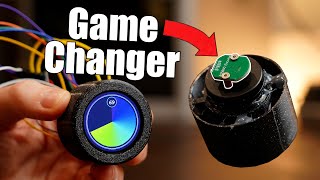
    Learn how to create a DIY LED ring light for potentiometer/rotary encoder and Arduino, driven by MAX7219 multiplexing chip. I will create a custom PCB in KiCad, and order it together with SMD assembly from PCBWay. The only part that I need to hand solder are the header pins. This module uses 32 SMD LEDs sized 0402 - those are very small and they would be hard to solder by hand. Is my DIY LED ring light cheaper compared to the one that you can buy on AliExpress? Well, it depends. It is slightly cheaper if you order 10 pieces, but it would be much cheaper for higher quantities.
    ------------------------------------------------------
    PCBWay is a service for manufacturing custom PCBs. If you click the link above, you will get a coupon for $5, which is exactly the price of 10 pieces of custom PCBs. In that case, you will only pay for shipping. Do you have any experience doing this? Please let me know in the comment section!
    ------------------------------------------------------
    Do you have any questions? Suggestions for the next video? Please put those down in the comment section. I try to answer as many questions as I can. Thank you for watching, reading the video description and I hope to see you next time. Good luck with your projects!
    ------------------------------------------------------
    #arduino #led #pcb
    ------------------------------------------------------

Комментарии • 183

  • @upir_upir
    @upir_upir  5 месяцев назад +16

    All the source files are on GitHub: github.com/upiir/diy_led_ring_light_arduino

    • @OMNI_INFINITY
      @OMNI_INFINITY 5 месяцев назад

      Thanks👍🏻

    • @pojuh645
      @pojuh645 5 месяцев назад

      can you maybe add a lowcut to your audio file so my subwoofer doesnt explode while you are speaking and i have to go and turn down my subwoofer to listen to voice?

  • @pavelino17
    @pavelino17 4 месяца назад +11

    Fastest and best Keycad explanation I have seen till now

  • @Barzar100
    @Barzar100 5 месяцев назад +29

    The quality of your videos is very impressive. Awesome work. You deserve much more Attention.

    • @upir_upir
      @upir_upir  5 месяцев назад +1

      Thank you for your nice words, I appreciate that!

  • @bimokayoba
    @bimokayoba 5 месяцев назад +8

    your Potentiometer tutorials helped me a lot on ardiuno, pcb design and wiring, thank you so much ♥
    KEEP UP THE GREATE WORK ☺

    • @upir_upir
      @upir_upir  5 месяцев назад +2

      Thank you for your nice comment, I´m glad it was helpful, and good luck with your projects!

  • @ethkid8925
    @ethkid8925 5 месяцев назад +9

    Dear algorithm, THIS is the good stuff!!
    Thanks man, as other pointed out, looking forward to a neopixel version!

    • @upir_upir
      @upir_upir  5 месяцев назад

      Thank you, I´m glad you have enjoyed the video and I will post the neopixel project soon.

  • @johnpomaro1731
    @johnpomaro1731 5 месяцев назад +5

    Thank you for detailing the complete process and even other options!

    • @upir_upir
      @upir_upir  5 месяцев назад

      You are welcome, I’m glad it was useful.

  • @Tawnos_
    @Tawnos_ 5 месяцев назад +13

    Another option is to create extra parts that you delete after creating the circle. E.g. instead of 32 diodes taking 360 degrees at a spacing of 11.25 degrees/diode, you could have the tool place 39 diodes at a spacing of 9.23 degrees each and delete 7 of them to get 295.38 degrees of the original diodes

    • @upir_upir
      @upir_upir  5 месяцев назад +2

      Yes, that´s surely a possibility, and probably the simplest thing to do if the desired angles are somewhat matching.

  • @AFSMG
    @AFSMG 5 месяцев назад +5

    Excellent work as always. Waiting for the next job. All the best

    • @upir_upir
      @upir_upir  5 месяцев назад +1

      Thank you! If you are looking for the next potentiometer video, I still have a few tricks up my sleeve...

  • @wgm-en2gx
    @wgm-en2gx 4 месяца назад +1

    Thank you for getting straight to the point indicated in the title. A lot of videos string you along for the watch time. I did watch to the end. I can't image soldering them by hand and keeping them spaced equally!

    • @upir_upir
      @upir_upir  4 месяца назад

      Thank you for your comment and I appreciate the time spending watching this video. Hopefully it was helpful and you learned something new.

  • @MakenModify
    @MakenModify 5 месяцев назад +17

    Great tutorial. After your initial video on the LED-Ring I immediately jumped into KiCad and designed some with ws2812 LEDs. That way I just need 3 pin (Signal, +5V and GND) and have RGB. Keep up the great work. 👍

    • @upir_upir
      @upir_upir  5 месяцев назад +8

      Thank you for your comment. Have you ended up manufacturing that? I would be interested to see it. I´m thinking about using neopixels as well for a future video for the reasons mentioned.

    • @MakenModify
      @MakenModify 5 месяцев назад +6

      @@upir_upir yes I got some made, but also have a list of things I would change. If you want I send you some should not be to bad inside EU. Will likely not make a video any ways 😅

    • @GeekDetour
      @GeekDetour 5 месяцев назад

      Exactly! I just suggested the same thing, then I saw your comment.

    • @bogusF
      @bogusF 5 месяцев назад

      As a finished product, I'd prefer Max7219 over neopixels since the latter require very precise timing, whoch puts the arduino under a lot of stress. Might not be an issue if you use esp or other powerful μC

    • @satibel
      @satibel 4 месяца назад

      Note that unless they changed it since last time I used the led Library it's very inefficient in ram usage, as it allocates a byte per led, when you could use a single byte for the color of all the leds or generate them programmatically.
      (I modified it to remove the delay after sending, so I could send individual LED colors without using ram)

  • @Hotrian
    @Hotrian 4 месяца назад +1

    Gotta add onto the props for the Kicad run down! Thank you so much for running us quickly through all the processes needed for this board including placing the order! I had always wanted to give it a shot but didn't realize how easy it was, and all the other tutorials I had looked into made the schematic softwares seem so intimidating!

    • @upir_upir
      @upir_upir  4 месяца назад

      Thank you for your nice words, I´m glad you enjoyed the video and that it was helpful. New software is usualy always intimidating, and unfortunately people often times overcomplicate things. Not to say that KiCad is not powerful tool with a lot of features, but for simple projects, you don´t really need to touch most of the buttons. Good luck with your project and good luck ordering your first pcb!

  • @cyrilengmann
    @cyrilengmann 4 месяца назад +1

    I just learned so many different KiCad tips and tricks from the video. Thanks!

    • @upir_upir
      @upir_upir  4 месяца назад

      That´s great to hear!

  • @tahakhan88
    @tahakhan88 4 месяца назад +1

    Just because you gave away key information at the beginning of the video, I watched the whole video all the way till the end. We need more people like you on youtube

    • @upir_upir
      @upir_upir  4 месяца назад

      I appreciate that! Thank you, and I hope that it was helpful. Good luck with your projects.

  • @Bass42894
    @Bass42894 5 месяцев назад +1

    Very good video. Keep making these, I'll use this as a base design for a big USB commune knob I want to make for my computer! Thank you so much for the work you've put into these videos. Always excited for a new upload.

    • @upir_upir
      @upir_upir  5 месяцев назад

      Thank you! What are you going to use this USB knob for?

  • @stetytielemans
    @stetytielemans 5 месяцев назад +14

    I have found that if you make a circular array with only 1 component of the ones you want to make a circle with, so delete all but 1 component, it will assign the correct names and pads to the new footprints.

    • @upir_upir
      @upir_upir  5 месяцев назад +1

      I have tried that, but somehow it was not working properly, it assigned the correct names, but the wiring was lost. I guess there is still a lot to learn..

    • @noahkiser
      @noahkiser 5 месяцев назад +2

      @@upir_upirafter using the array tool, once you ensure the reference designators are correct, Update PCB from Schematic again and it will refresh the netlist/wiring

    • @masterluu8
      @masterluu8 5 месяцев назад +1

      @@upir_upir For the plugin, couldn't you add more LEDs than you need and then delete the ones where the gap should be?

  • @linux2420
    @linux2420 4 месяца назад +2

    Wow! This looks really nice, i kind of want to use this to make a custom volume knob for my computer now... thank you for sharing this!

    • @upir_upir
      @upir_upir  4 месяца назад

      Cool! Don’t forget to post your project once it’s ready, sounds very interesting!

  • @jlnrdeep
    @jlnrdeep 5 месяцев назад +1

    Nice and detailed tutorial, kudos for the amazing work.

    • @upir_upir
      @upir_upir  5 месяцев назад

      Thank you, I´m glad you like it!

  • @tyrelllaszlo6024
    @tyrelllaszlo6024 5 месяцев назад +1

    Nice Project and thanks for the KiCad tutorial. 😊

    • @upir_upir
      @upir_upir  5 месяцев назад

      Thank you, and you are welcome!

  • @timmyj5575
    @timmyj5575 5 месяцев назад +3

    Really apprecciate telling us the final cost at the beginning! Thank you

    • @upir_upir
      @upir_upir  5 месяцев назад +1

      You are welcome, hope you liked the video!

  • @m.vanhat
    @m.vanhat 4 месяца назад +1

    Zrovna nedávno jsem je hledal ale ta cena je moc... super alternativa a super video!!

    • @upir_upir
      @upir_upir  4 месяца назад +1

      Super že to přišlo vhod!

  • @brianstems5246
    @brianstems5246 5 месяцев назад +1

    I love this - it gives me a lot of creative ideas for different interface designs. I'm just getting into electronics and something like this is really motivating to watch before reviewing not particularly exciting topics like math and basic resistor networks. (edit - just checked your other content and I could watch a video a day to keep motivated before reviewing and practicing on my own)

    • @upir_upir
      @upir_upir  5 месяцев назад

      Thank you, that´s great to hear. Please feel free to watch the other videos and good luck with your projects!

  • @nicnewdigate
    @nicnewdigate 5 месяцев назад +1

    Great content ❤thank you, really enjoyed watching it

    • @upir_upir
      @upir_upir  5 месяцев назад

      Thank you, I´m glad you like it! Good luck with your projects.

  • @EvenTheDogAgrees
    @EvenTheDogAgrees 5 месяцев назад +2

    Personally, I prefer the aesthetic of the original model, but I love how your new one is pin-compatible so people can choose. Great video, as usual.

    • @upir_upir
      @upir_upir  5 месяцев назад

      Thank you, I´m glad you like it! Yep, the new one would look better with some enclosure.. maybe next time.

  • @OMNI_INFINITY
    @OMNI_INFINITY 5 месяцев назад +1

    Thanks for posting that! Don’t know why ring light pots haven’t seemed as common recently. Good to solve that. 1206 edition for assembling without PCB way would be nice also. I don’t have any kids though and don’t want to personally lay out all of those components for a pot. If I make a synth, would be nice to have those though.

    • @upir_upir
      @upir_upir  5 месяцев назад

      Thank you for your nice comment, I´m glad you like it. What is 1206?

  • @chrisw1462
    @chrisw1462 4 месяца назад +1

    You could get that multiplexer in a surface mount version that could go on the LED circuit board, so you only have to pay for one board instead of two. If you added 5 LEDs, then made the circle, you could then delete the extra ones in the positions you want empty.

    • @upir_upir
      @upir_upir  4 месяца назад

      Yes, that´s something I would like to try next.

  • @t1d100
    @t1d100 5 месяцев назад +2

    Here is a work-around process that I think will allow you to successfully use the first automatic circular array dispersal process to make the partial circle that you need to mimic the limited rotation of the knob... I have not tried it, but it should be easy and straight forward. You have 4 arrays of 8 LEDs. On the Schematic = Create an additional fifth array with about 6 LEDs. (I am estimating the number of LEDs by sight from your board-side video pictures.) These additional LEDs will be sacrificial place holders, so you can connect them electrically, in any manner. Go to the board side and automatically disperse all five arrays. Check the dispersal of the six sacrificial LEDs. If the gap size is not correct, adjust the number of sacrificial LEDs and repeat the process. When the gap is correct, lock the positions of all of the LEDs in the four 8 LED arrays, on the PCB board. Do not lock the fifth array of sacrificial LEDs. Go back to the schematic and delete the fifth array of sacrificial LEDs. You should be catching on, by now, so I want fill in all of the final details... Using the footprint assignment tool, etc. But, I will remind you to set the PCB update settings in such a way that your parts retain their original positions, when you update the PCB. If this saves you as much time and effort as I think it will, let me know and I will let you know where to send my fully completed module of your design Oh, and pin me?

    • @upir_upir
      @upir_upir  5 месяцев назад

      Thank you for your comment and the solution you've provided. I ended up with a simple script to rotate the LEDs, so your technique will take longer, but I would still be happy to send the PCB to you. Please send me an email.

    • @t1d100
      @t1d100 5 месяцев назад

      @@upir_upir Oh, no, you truly don't owe me anything. I was teasing; that's why I wrote" big grin." Is your better method the second one shown? You could use your better technique to make a permanent footprint, in the footprint editor. Then, you could use it in any project. Cheers.

  • @JarecFR
    @JarecFR 5 месяцев назад +1

    Love it.

  • @planker
    @planker 5 месяцев назад +1

    Excellent work.
    It's got to feel good holding this awesome creation. I watched the previous video and knew you were going to have this.
    My challenge this week is to duplicate a TM1637 seven seg disp. into a VFD tube disp. Just because I think it would be unusual and cool.
    The potentiometer rings would look sharp on a tube pre-amp.

    • @upir_upir
      @upir_upir  5 месяцев назад +1

      Thank you very much, I´m glad you like it. About your project - can you perhaps share more details? It sounds very interesting! I love VFD displays.

    • @planker
      @planker 5 месяцев назад

      @@upir_upir I'm trying to get my head around which driver or just do jfets, I want I2C for comms, so the TM1637 goes first then possibly TBD62783A, UND6118A or a darlington pair for drivers. In work as we speak.

  • @stylesoftware
    @stylesoftware 4 месяца назад +2

    Love your vids, your problem with the circle of leds can be fixed by what I call cheating. Simply add 4 or 6 more led's in your schematic, turn them into the circle, then either delete them or remove the LED from the BOM.

    • @upir_upir
      @upir_upir  4 месяца назад

      Thank you, I´m glad you like it! Yes, that would probably be the fastest and best way to solve this problem. Others were proposing writing a Python script, but my I don´t have enough knowledge for that - yet.

  • @BoostedVr5
    @BoostedVr5 5 месяцев назад +1

    i have the led ring housing using it in my car as a fully adjustable tractioncontrol potmeter i looked long for this cant thank you enough : )

    • @upir_upir
      @upir_upir  5 месяцев назад +2

      That sounds very interesting! Do you have any photos of your project?

    • @BoostedVr5
      @BoostedVr5 5 месяцев назад

      @@upir_upir yes i do im using it in my car with standalone ecu named Emublack 😁

    • @BoostedVr5
      @BoostedVr5 4 месяца назад

      @@upir_upir yes 😇

  • @Dsgj
    @Dsgj 5 месяцев назад +1

    This would be pretty cool to implement on a electric guitar!

    • @upir_upir
      @upir_upir  5 месяцев назад

      That´s a very interesting idea! I have an old guitar, so I might try that.

    • @Dsgj
      @Dsgj 4 месяца назад +1

      @@upir_upir yes please!

  • @onebacon_
    @onebacon_ 4 месяца назад +2

    Placing them in a circle could have been really easy. Just add more LEDs, generate the circule and then delete the unwanted LEDs

    • @upir_upir
      @upir_upir  4 месяца назад

      Yep, that´s probably the easiest way to solve this.

  • @radnukespeoplesminds
    @radnukespeoplesminds 5 месяцев назад +1

    Both look great! When I need to place footprints in particular patterns I find it easier to just write a python script. Kicad has nice scripting functionality.

    • @upir_upir
      @upir_upir  5 месяцев назад

      Thank you! Do you have any good resources for writing python scripts for KiCad?

  • @stevenpaul9307
    @stevenpaul9307 3 месяца назад +1

    great work! thank you.
    I did something similar. I'd like to show you in a fee days.

    • @upir_upir
      @upir_upir  3 месяца назад

      That´s cool, please feel free to post link, I would like to see it!

  • @eugeniusz7144
    @eugeniusz7144 4 месяца назад +1

    Hmmm as for the plugin the idea which came to my mind is to add several additional LEDs, run the plugin to full circle and then detete the excess

    • @upir_upir
      @upir_upir  4 месяца назад +1

      Yep, that’s probably the easiest way how to do it.

  • @bryantaylor2523
    @bryantaylor2523 5 месяцев назад +1

    You probably could have gotten that circular array plugin to work for your purpose by adding a few extra LEDs that weren't connected to anything and then delete the extras after it arranges them all.

    • @upir_upir
      @upir_upir  5 месяцев назад

      Yep, someone already mentioned this approach, and I think it´s probably the best solution.

  • @dougcox835
    @dougcox835 5 месяцев назад +1

    Your comments about volume pricing remind me of a long time ago when a friend of mine wanted to make a computer plug in board and sell them. I told him that the whole thing would be cheaper per board in quantity so he ordered and built 100. I think he maybe sold 3 and gave some away. Unless you know you will be actually selling some quantity it's better to just go with the low quantity lrip. You can always buy more when interest peaks.

    • @upir_upir
      @upir_upir  5 месяцев назад

      Fully agree, that’s why I only went with 10 pieces that I will give away for free anyway. It’s very simple to fall into the trap of ordering more units only because the price for one unit will drop. I have made this mistake way too many times.

  • @dougcox835
    @dougcox835 5 месяцев назад +1

    To make this nest level you could use RGB leds. They would be simpler to work with as they are serially addressed so no need for that mux chip. Not sure about what you might do with the collors though. Maybe have them go from blue to red like temperature or with audio maybe have them pulsate brightness with the levels. Actually that might work fine with single colors. Perhaps have a knob perform multiple functions with the leds showing which function is active. But for that maybe an encoder would be better because the knob wouldn't be in the right place when changing functions.

    • @upir_upir
      @upir_upir  5 месяцев назад

      Yep, I do plan to create a next iteration using the neopixels and play with colors a little bit more.

  • @noelswedzinski4498
    @noelswedzinski4498 5 месяцев назад +1

    This is one of those items I'd like to buy 20 of at once just to have for when I have a use for it, something like a group bulk buy would be awesome

    • @upir_upir
      @upir_upir  5 месяцев назад

      Do you already have some project in mind?

  • @tangocharlie5509
    @tangocharlie5509 5 месяцев назад +1

    @5.40 You probably know that: If there are a lot of crossing connexions, it's more readable to use "Local Label" or "Global Label" to interconnect those 32 leds.

    • @upir_upir
      @upir_upir  5 месяцев назад

      I actually don´t know it yet, so this information was very helpful. Thank you!

  • @yerwol
    @yerwol 5 месяцев назад +1

    I've got a KiCAD plugin which is designed to place components in a circle like that but just by setting a field value and pressing one button - are you interested in seeing it at all as it would save manually setting every LED!

    • @upir_upir
      @upir_upir  5 месяцев назад

      Sounds interesting! I’m sure other people would appreciate such plug-in as well. Could you provide more details? Thank you!

  • @SloBloLabs
    @SloBloLabs 5 месяцев назад +1

    @upir: You could use the Python API to fetch the LED footprint from the library and create 32 copies with the right position and rotation applied. It is not that hard to do.

    • @upir_upir
      @upir_upir  5 месяцев назад

      Good idea. I need to try Python. Do you have any good resources regarding python in KiCad?

    • @SloBloLabs
      @SloBloLabs 4 месяца назад +1

      @@upir_upir Yes, just made a video on the topic a few weeks ago.
      DIY Cable Holder - with detailed Python/KiCad Tutorial how to make it
      ruclips.net/video/-bsLeLYtkmE/видео.html

    • @upir_upir
      @upir_upir  4 месяца назад

      @SloBloLabs cool, I will check it. Thank you!

  • @Mtaalas
    @Mtaalas 5 месяцев назад +2

    If you made a panel with 10 or 20 PCB's, then your unit cost would crash quite low very fast.
    Two PCB's per panel is very wasteful when PCB's are so small.
    Design for production is all about optimizing every small thing and making sure there's as little wasted time and resources as possible :)
    It's completely different part of electronics design that must be mastered if you ever want to make real work...

    • @upir_upir
      @upir_upir  5 месяцев назад

      Yep, I’m pretty sure that for hundreds or thousand pieces, you can get even better price than mentioned in the video. I only need a few pieces for testing, and that was the reason for two pcbs on panel. Anyway, would you recommend any book/video/course on this topic?

  • @adriangunnarlauterer4254
    @adriangunnarlauterer4254 4 месяца назад +1

    You should consider adding the controller to the same PCB as the Potentiometer pcb, reducing amount of connectors and pcb, reducing cost and size.

    • @upir_upir
      @upir_upir  4 месяца назад

      Yes, that would be the next step for the mentioned reasons. I´m just not that versed in PCB design yet, so I´m taking small steps.

  • @JonnyWaldes
    @JonnyWaldes 5 месяцев назад +1

    It's almost cooler if you take away the knob with the tick mark

    • @upir_upir
      @upir_upir  5 месяцев назад

      Yep, with the LEDs, the tickmark is not helping too much, and it´s also hard to keep those two in sync.

  • @JyskMaker
    @JyskMaker 5 месяцев назад +1

    Love your video, how about putting som 74xx ttl component on it to count the encoder to make it so you dont need the arduino. Up/Down counter

    • @upir_upir
      @upir_upir  5 месяцев назад +1

      Thank you. Unfortunately, I´m not familiar with the proposed components, but I agree that making this module stand-alone would make it more usable. Actually, in one of my older videos, I was testing a very similar module from DFRbobot, with a rotary encoder and a few LEDs around - although not 32. I will still explore other options in a future videos.

  • @jetli740
    @jetli740 5 месяцев назад +1

    you need to put a circular screen in the knob, i seen few have them now

    • @upir_upir
      @upir_upir  5 месяцев назад

      Yep, I´m testing a few of those, but they are not very simple to use..

  • @urdnal
    @urdnal 5 месяцев назад +1

    To make the circle I'd have added two or three more LEDs, used the plugin then deleted them.

    • @upir_upir
      @upir_upir  5 месяцев назад

      That would probably be the easiest way to do it.

  • @Ivan.Wright
    @Ivan.Wright 3 месяца назад +1

    Could you please do a KiCad video where you take us through your process for using it?

    • @upir_upir
      @upir_upir  3 месяца назад

      I already have a few videos where I use KiCad and I show step-by-step tutorial. Is there anything particular that you are looking for?

    • @Ivan.Wright
      @Ivan.Wright 3 месяца назад +1

      @@upir_upir I was thinking something like a long form vid, maybe a live stream, where it feels more like a ride along than a tutorial. Essentially I'd like to just watch you build something from start to finish in KiCad without the kind of "training wheels", for lack of a better word, that get applied when approaching the problem as a tutorial. An analogy for the distinction I'm trying to make would be like watching a professional tennis player teach a class on tennis vs watching them play an actual match.
      While there will naturally be much less verbalized explanation and explicit instruction in the kind of content I'm suggesting I think there will be more to study and learn from overall.
      That's just my thoughts and suggestion anyway

    • @upir_upir
      @upir_upir  3 месяца назад +1

      @@Ivan.Wright Thank you for the clarification, it makes a lot of sense, but I´m not sure if I have enough knowledge at this point, as I´m still learning how to use KiCad. And I would still consider myself being a beginner. That said, I will keep that in mind and hopefully sometime in the future as my knowledge grows I will be able to record such video. Thank you again for your comment!

    • @Ivan.Wright
      @Ivan.Wright 3 месяца назад

      @@upir_upir I understand your concern. However, I must point out the potential for your knowledge to grow faster by producing such content as individuals who are more proficient than you can point out to you certain faults they've previously dealt with. Prefacing the video with a statement of your approximate skill level, regardless of that level as long as it's relatively accurate, is welcome in the RUclips space in my understanding.
      Again, just my thoughts. Love your vids and look forward to the prospect of one day seeing a video like that which I proposed.✌️

  • @NavySturmGewehr
    @NavySturmGewehr 5 месяцев назад +1

    I don't remember if I've asked before, but is it possible to cover the entire design process of making a custom board that uses something like the esp32?

    • @upir_upir
      @upir_upir  5 месяцев назад

      Not yet - as I don’t have enough knowledge for a project like this. But that would hopefully change in the future…

  • @satibel
    @satibel 4 месяца назад +1

    Where you save a ton of money is if you make an actual product, you can have 5 pots like that for only a few bucks extra.

    • @upir_upir
      @upir_upir  4 месяца назад

      What do you mean by "make an actual product". I.e., how making this a product will save a ton of money? I want to save a ton of money :)

    • @satibel
      @satibel 4 месяца назад

      @@upir_upir I meant if you're integrating that in a pcb, the main cost is the pcb, so if you have a pcb with 32*5 leds it's much cheaper than 5 pcb with 32 leds, because most of the costs are fixed costs per pcb and per component type

  • @InfluentialStudios
    @InfluentialStudios 4 месяца назад +1

    You should work with Adafruit to have these made at scale and placed for sale.

    • @upir_upir
      @upir_upir  4 месяца назад

      You can actually buy a few pre-made modules. I will cover those in the next video.

  • @GeekDetour
    @GeekDetour 5 месяцев назад +1

    Hi Upir (is it your name?) An idea for a way simpler and more flexible pub design is using individually addressable LEDs - they will be all connected in series and you just need 3 wires: +, - and data. Software will be easier too - and with such a simpler wiring, you will easily be able to have a larger diameter on the LEDs Ring. I loved this project since the first time I saw it, but I always imagined what would it be with addressable LEDs instead of a multiplexer.

    • @upir_upir
      @upir_upir  5 месяцев назад

      Thank you for your comment, and yes - I do plan to experiment with neopixels a little bit more, hopefully soon.

  • @nagi603
    @nagi603 4 месяца назад +1

    8:38 what if you.... add a few extras and delete them from the circle? Granted, more annoyance with more components that you ultimately delete.

    • @upir_upir
      @upir_upir  4 месяца назад

      Yes, that would probably be the best solution. Thank you for your comment.

  • @benjaminauer
    @benjaminauer 5 месяцев назад +1

    possible version with encoder and fully closing circular ring?

    • @upir_upir
      @upir_upir  5 месяцев назад

      Yep, that´s on my to-do list for sure.

  • @somedude2492
    @somedude2492 5 месяцев назад +2

    8:21 what about using say 38 LEDs, making a circular array, then deleting LEDs 33 though 38 to leave the gap you want?

    • @upir_upir
      @upir_upir  5 месяцев назад

      Yep, that would be probably the best approach.

  • @SodaWithoutSparkles
    @SodaWithoutSparkles 5 месяцев назад +1

    Can you modify the angle value in 7:56 to 10.625, that way you would leave a ~20 degree gap

    • @upir_upir
      @upir_upir  5 месяцев назад

      Yep, that would be probably the simplest way how to solve this.

  • @xploitedclam9235
    @xploitedclam9235 2 месяца назад +1

    I'm curious, how would you go about actually mounting this in an enclosure? I've been considering it a good amount, and the issue i keep seeing is that both the led ring and encoder would be only secured to the pcb, as you would need to have a hole the entire size of the led ring in the faceplate.. which doesnt seem ideal for real world use. Lots of stress going into the solder joints and pcb board.

    • @upir_upir
      @upir_upir  Месяц назад

      I have recently found out that for many guitar pedal effects, the foot switch is only mounted in the pcb. It uses many solder joints, but still, you press it with your foot.. I think the led ring should be fine, there will not be a lot of stress.

    • @xploitedclam9235
      @xploitedclam9235 Месяц назад

      ​@@upir_upir that doesnt' sound right ha. I've made plenty of guitar effects (this is in fact for a guitar pedal im designing) and have seen countless gutshots of pedals, never have i seen the footswitch not securly mounted to the case with the nut. Even when its mounted to the pcb, the pcb isn't providing any of the strength, its still mounted with the nut in the enclosure. Same with pot's. Please point me to a pedal where its just mounted on the pcb. I can link you to hundreds where it is mounted on the enclosure. If anything its the other way, the pots and footswitch are securing the pcb inside the enclosure. The pcb's in there are not mounted with standoffs or anything, there secured from the pots / swtiches etc that are mounted in the enclosure

  • @gergelysoki1705
    @gergelysoki1705 5 месяцев назад +4

    does it go to 11?

    • @upir_upir
      @upir_upir  5 месяцев назад +1

      Even better, it does go to 32!

  • @tamer27antepli
    @tamer27antepli 5 месяцев назад +1

    Pls dj and studio gear engineers, we want cool looking stuff

    • @upir_upir
      @upir_upir  5 месяцев назад

      There are many cool looking stuff out there, but they are way too expensive, like pretty much everything from Teenage Engineering..

    • @tamer27antepli
      @tamer27antepli 5 месяцев назад

      @@upir_upir yes but imagine a dj mixer with pretty ring lights and stuff

  • @xbox360Rob
    @xbox360Rob 5 месяцев назад +1

    63 bucks, damn. Jlcpcb woulda been maybe 30

    • @upir_upir
      @upir_upir  5 месяцев назад

      Any idea why it would cost half the price?

  • @oyamamahiro-chan
    @oyamamahiro-chan 5 месяцев назад +1

    13:24 when you see it

  • @Barzar100
    @Barzar100 5 месяцев назад +1

    I come from Germany. Can I buy one these pcb's from you?

    • @upir_upir
      @upir_upir  5 месяцев назад

      Sure, please send me an email, it’s in the about page of this channel.

  • @danbrit9848
    @danbrit9848 5 месяцев назад +1

    i need a kit that i dont need to code ...just buy it like any other switch and connect it up ...i cant code but want them badly

    • @upir_upir
      @upir_upir  5 месяцев назад +1

      Sure, I have a video with a module that you can buy and use - ruclips.net/video/e2UNsZPjHkk/видео.html

    • @danbrit9848
      @danbrit9848 5 месяцев назад +1

      @@upir_upir thank you so much

  • @user-me5eb8pk5v
    @user-me5eb8pk5v 5 месяцев назад +1

    You can tie fishing line too a long needle and bent it into a circle to create a varactor, pull the fishing line then add voltage drops, so, purchase a analog to digital IC. iTS NOT ONLY CHEAPSKATE, BUT ULTRA RARE.

    • @upir_upir
      @upir_upir  5 месяцев назад +2

      What. I mean, what?

  • @chaosordeal294
    @chaosordeal294 4 месяца назад +1

    Ten bucks isn't great, but it's not a bad price at all. I have a nice button pad with three dials so I don't need a custom pot. So, why am I watching this video? Work avoidance therapy.

    • @upir_upir
      @upir_upir  4 месяца назад

      Work avoidance therapy is something that I practice all day long :)

  • @XiaZ
    @XiaZ 5 месяцев назад +1

    Ain't no way that 10x PCBA cost $63, you must be doing something wrong.

    • @upir_upir
      @upir_upir  5 месяцев назад

      Do you think it’s too expensive? Or to cheap?

    • @XiaZ
      @XiaZ 5 месяцев назад +1

      @@upir_upir Way too expensive, PCB should cost no more than $8 for 10, the 0402 led components from my calculation was $7.672 loading fee included, and assembly fee is around $10, total to around $26

    • @upir_upir
      @upir_upir  5 месяцев назад

      @XiaZ if you can post a link to an online service that will manufacture it for that price, I would be very happy to try it. Thanks!

    • @XiaZ
      @XiaZ 5 месяцев назад

      @@upir_upir I don't think posting other services in a PCBWay sponsored video is a good idea.

    • @RJ_Eckie
      @RJ_Eckie 5 месяцев назад

      @@XiaZPCBWay is not controlling the conversation here. If you can help the community with information, please do

  • @calpardo
    @calpardo 4 месяца назад +1

    10:20 real men don't do auto-routing 😠

    • @upir_upir
      @upir_upir  4 месяца назад

      I´m not quite sure if my manual routing would look much better. Probably not.

  • @kphaxx
    @kphaxx 5 месяцев назад +1

    Why would you traffick potentiometers for sxeaul services?

    • @upir_upir
      @upir_upir  5 месяцев назад

      What?

    • @No1sonuk
      @No1sonuk 4 месяца назад

      @@upir_upir I think someone doesn't know the double-meaning of the word "pimp".

  • @dilirink9222
    @dilirink9222 5 месяцев назад +1

    19 $ 😦

    • @upir_upir
      @upir_upir  5 месяцев назад

      Too expensive? Too cheap?

  • @mertblt7456
    @mertblt7456 5 месяцев назад +1

    i cloned this procekt its 3 dollars

    • @upir_upir
      @upir_upir  5 месяцев назад

      Where did you get it for 3 dollars?

  • @Kulderzipke123
    @Kulderzipke123 5 месяцев назад +3

    First

    • @upir_upir
      @upir_upir  5 месяцев назад +3

      I was first :)

  • @Inductable
    @Inductable 5 месяцев назад +30

    Your schematics are a mess of wires. You could have made them easier to work with if you spent a few minutes cleaning them.

    • @upir_upir
      @upir_upir  5 месяцев назад +20

      You are right, I wanted to have it connected as fast as possible to move on to pcb design, I could have used a little bit more time to make it pretty..

    • @kacpe8766
      @kacpe8766 5 месяцев назад +12

      You'd faint if you saw my easyeda folder

    • @derex47
      @derex47 4 месяца назад +23

      Here comes the chief engy to complain about the free schematics

    • @SomeoneRandomDuck
      @SomeoneRandomDuck 4 месяца назад +1

      🤓

    • @Hawk7886
      @Hawk7886 4 месяца назад

      ​@@derex47OK

  • @velizyhills
    @velizyhills 2 месяца назад +1

    Hello!
    First of all BRAVO for your work and your very educational videos, even if sometimes the code description goes a little fast...
    I realized the project described in "Pimp My Potentiometer (again)". It works well but the legs of the circular display are not easy to insert into the PCB.
    In order to make the version "Pimp my Potentiometer -CHEAPER-", can we order other leds than white (NCD0402W1) from PCBWay?
    Chris
    Velizy 78 Yvelines FRANCE

    • @upir_upir
      @upir_upir  2 месяца назад

      Thank you for your nice words, I´m glad you like it! Why are the legs not easy to insert? For the custom PCB with LEDs, yes, you can order different colors as well.