This was by far the best explanation of how to test a chrystal, as of up to now i had a very fuzzy knowledge how they behave (other then the obvious, oscillating). Big thanks, from Magnus
good work and yes it is resonance and that's what happens when bridges collapse bridge collapsed because moderate winds produced aeroelastic flutter that was self-exciting and unbounded
I am confused here. You refer to the circuit at the beginning as an oscillator, but then you refer to the component as an oscillator. Is that just a crystal, not an oscillator? Or are they both oscillators? I am hew to electronics, so sorry if this seems like a silly question. Thanks.
The component itself is called a "crystal oscillator". When a voltage is applied to it, it oscillates at some pre-determined frequency. There are also circuits called "oscillators" which also oscillate at some pre-determined frequency. Some oscillator circuits also use crystal oscillators, but many don't.
The Quartz crystal in a given Quartz oscillator vibrates at its own native resonance frequency (in low frequency application, in higher frequency Quartz oscillators are much more complicated due to the use of harmonic overtunes to generate the frequency, by either selecting the tones or mix them) - controlled by the cut thickness, meaning the time (measured in Hertz) you get from them vibrating electroacoustically should remain unchanged, especially with the special ovenized Quartz oscillators. They're the most common clock source as well.
@@Enigma758 I beg to differ. This component is a crystal. It will not oscillate. Having two leads only, the crystal is connected between the two leads. By itself it will not oscillate. It can act as a narrow-bandpass filter as shown.
@@milantrcka121 Hi Milan, when a piezoelectric material (like a quartz crystal) is subjected to a electric current, it vibrates. It does not need an external oscillator in order to oscillate. In the video above, we are seeing that it reacts in a certain way when a resonant frequency is applied, but that is normally not how a crystal is used. It can be modeled as an RLC circuit which oscillates when powered. From wikipedia: "The quartz oscillates at a stable resonant frequency, behaving like an RLC circuit, but with a much higher Q factor (less energy loss on each cycle of oscillation)."
Paul, your timing is impeccable. I plan to spend some time this weekend testing a bunch that I recovered from items people have discarded. Keep up the good work and thank you.
This is the kind of thing you'd need at the weirdest time and no combination of search terms will help you find an answer. Now it does. Just checked my handheld scope w/ function generator. It works well enough, but doesn't go past 10MHz... Gonna have to find an affordable portable function generator that gets closer to frequencies we're likely to be working with.
Not my usual experience, mind you. On rare occasions, even I can pan something out right away like that. Normally, my attempts turn out comical at best, and... just go downhill from there to say the least.
Great vid thanks. Tested a suspected faulty crystal 12MHZ. resonance gave 750mV and other frequencies gave 200mV. is this increase sufficient? in the example it went from 800mV to 10 V! I understand this is dependant on crystal however is there a percentage increase which passes a good crystal?
Good question. Crystal oscillators typically require a pair of capacitors which provide feedback in order for it to oscillate properly. You would have to first build a circuit with the correct value pair of load capacitors (as per the datasheet which you may not have) and then power the oscillator. If you did that, you could measure the frequency directly. The approach in the video avoids having to to all that. BTW, it looks like he borrowed this idea from a "Hackaday" post. If you read the comments from the original Hackaday post, it's mentioned that you could also build a circuit and test it directly.
@@Enigma758 A crystal oscillator is a complete circuit, including a crystal, that produces an oscillating output. Crystal plus two caps is still not a crystal oscillator; most of the oscillator circuit is (in this case) on the microcontroller chip. BTW I'm not sure how good for the xtal it is to have it ringing at 12V p-p like that. Seems like it might shorten its life. All good fun though 🤪
@@my.own.devices It all boils down to semantics. I think the OP was getting hung up on that too which is why I responded. Typically the part itself is referred to as a "crystal oscillator", but to your point, it must be in a proper circuit in order to "oscillate". I agree that applying 12v directly is not a good idea. There should at least be a current limiting resistor in the path to avoid damaging the crystal (in the original Hackaday article, someone also mentioned that in the comments). In another video, he applies 100V+ directly to an expensive nixie tube with no current limiting resistor so beware of any advice given on this channel!
What happens if the resonant frequency is 16.525Mhz? Does the voltage rise as you approach resonance, so that you can search for the peak and get it exact by checking rising it falling amplitude, or do you need to know the exact frequency in the first place so you can only check the crystal is good at that frequency?
Looks like I should assemble a clock source tester... Especially for quartz crystals and even MEMS oscillators so I can sort them out by frequency and as well as operating voltage. At least MEMS oscillators are better clock sources so I can make high quality PLL-based Quartz resonator tester for cheap.
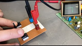
Or just use a $40 NanoVNA. No sig gen or oscilloscope needed, (it has a sig gen built in if you need one for other applications,) and it provides precise frequency of operation info and all the parameters you might want or need in order to design crystal filters or other sorts of filters, or analyze antennas, etc. BTW, that is just a crystal being tested, not a crystal oscillator.
This kind of video is so cool. I have been searching YT for similar videos; like what can we use the scope for, to test fun stuff, but did not find much. Found something for audio here, that was also cool. Just a suggestion: videos of using a scope to do fun stuff like this. Sometimes i am scared ill blow up something when probing. Thanks and thanks again for all of the time you put in this, Cheers ! JF
Thank you!!! This short video make understanding how to test an oscillator or determine its frequency very easy. After two hours of research I was about ready to pull my hair out if I found yet another page of AI generated content or the same cut and pasted article with an equivalent circuit and a bunch of graphs. I don't care about any of that. I'm not an engineer. I just wanted to know how to test an oscillator and your video was perfect. Great job. Thanks for sharing!
another wonderful video. 🥳 O by the way I was interested in that bench oscilloscope Kiprim DS1202 and Amazon did not have any? I just wanted the price mostly. 😎 Thank you.
First, you displayed and tested a crystal -- NOT an oscillator. Second, Q~10,000, so you MUST come extremely close to resonance to notice an increase in amplitude. Frequency changes due to temperature might easily cause one to miss resonance unless frequency increments are 16 MHz/10,000 or less.


The same test works on speakers as well. It's an easy way to root out buzzing.
@Paul Tribbey - Interesting. Can you elaborate more on this? Thx!
@@surgingcircuits6955 piezzo buzzers maybe ?
You threw the board at least twice 🤯
That is a neat trick! Never seen that before. ☮️
This was by far the best explanation of how to test a chrystal, as of up to now i had a very fuzzy knowledge how they behave (other then the obvious, oscillating). Big thanks, from Magnus
Good one. Now I can test my 16MHz crystals I bought overseas for future Arduino type projects. 👍
Great 👍
good work and yes it is resonance and that's what happens when bridges collapse
bridge collapsed because moderate winds produced aeroelastic flutter that was self-exciting and unbounded
isn't the Vpp 10V on the high impedance of the scope input?! thanks for your inspiration and all the best, bemi
Thank you. This was helpful to test out the crystals in my Collins 75A-4. Subscribed.
Hello Paul, nice video, thank you.. Happy New Year. Best wishes from Germany
Very nice video... Thanks for sharing your knowledge...
Good information.
Love your tips, nice job Paul.
I am confused here. You refer to the circuit at the beginning as an oscillator, but then you refer to the component as an oscillator. Is that just a crystal, not an oscillator? Or are they both oscillators? I am hew to electronics, so sorry if this seems like a silly question. Thanks.
The component itself is called a "crystal oscillator". When a voltage is applied to it, it oscillates at some pre-determined frequency. There are also circuits called "oscillators" which also oscillate at some pre-determined frequency. Some oscillator circuits also use crystal oscillators, but many don't.
The Quartz crystal in a given Quartz oscillator vibrates at its own native resonance frequency (in low frequency application, in higher frequency Quartz oscillators are much more complicated due to the use of harmonic overtunes to generate the frequency, by either selecting the tones or mix them) - controlled by the cut thickness, meaning the time (measured in Hertz) you get from them vibrating electroacoustically should remain unchanged, especially with the special ovenized Quartz oscillators. They're the most common clock source as well.
@@Enigma758 I beg to differ. This component is a crystal. It will not oscillate. Having two leads only, the crystal is connected between the two leads. By itself it will not oscillate. It can act as a narrow-bandpass filter as shown.
@@milantrcka121 Hi Milan, when a piezoelectric material (like a quartz crystal) is subjected to a electric current, it vibrates. It does not need an external oscillator in order to oscillate. In the video above, we are seeing that it reacts in a certain way when a resonant frequency is applied, but that is normally not how a crystal is used. It can be modeled as an RLC circuit which oscillates when powered. From wikipedia:
"The quartz oscillates at a stable resonant frequency, behaving like an RLC circuit, but with a much higher Q factor (less energy loss on each cycle of oscillation)."
@@Enigma758 I see. Thanks.
Thanks for the comment re throwing parts about 😄😄😄
Can you find the resonant frequency of a piezo buzzer/transducer this way as well?
Never tried it, but I will now!
Another cool video, thanks PAUL 👍💚🇮🇪🙏🏼
Paul, your timing is impeccable. I plan to spend some time this weekend testing a bunch that I recovered from items people have discarded. Keep up the good work and thank you.
This is the kind of thing you'd need at the weirdest time and no combination of search terms will help you find an answer. Now it does.
Just checked my handheld scope w/ function generator. It works well enough, but doesn't go past 10MHz... Gonna have to find an affordable portable function generator that gets closer to frequencies we're likely to be working with.
I was able to find the source of this from a single google search which pointed me to Hackaday.
Not my usual experience, mind you. On rare occasions, even I can pan something out right away like that. Normally, my attempts turn out comical at best, and... just go downhill from there to say the least.
Hello ,
I don,t fined any data of Scopemeter Voltcraft Dscope 707, you help me for this oscope?
Very useful. Thank you very much sharing your skills.
Hi friend thanks for the informative video
Great vid thanks. Tested a suspected faulty crystal 12MHZ. resonance gave 750mV and other frequencies gave 200mV. is this increase sufficient? in the example it went from 800mV to 10 V! I understand this is dependant on crystal however is there a percentage increase which passes a good crystal?
Very nice very nice explained 👍
The voltage is higher (about double) because the scope is high impedance and the 5Vpp in 50 ohm.
Very impressive. You are thi man.
What would be your definition of resonance frequency. ?
Wouldn’t a voltage across the crystal oscillate at the frequency of the crystal. Wouldn’t the oscilloscope display this wave? 4:52
Good question. Crystal oscillators typically require a pair of capacitors which provide feedback in order for it to oscillate properly. You would have to first build a circuit with the correct value pair of load capacitors (as per the datasheet which you may not have) and then power the oscillator. If you did that, you could measure the frequency directly. The approach in the video avoids having to to all that.
BTW, it looks like he borrowed this idea from a "Hackaday" post. If you read the comments from the original Hackaday post, it's mentioned that you could also build a circuit and test it directly.
Way cool!
you are showing a 16 MHz, crystal, a crystal oscillator contains active components such a a transistor to make it oscillate.
Nice! Might you show an octopus for other components? 73 DE W8LV BILL
What crystal resonator do touchscreen fan control devices have?
Neat, love it! :)
Nice video! But technically, it is a crystal not an oscillator. Crystal oscillators have 4 pins.
I assume you say that because the two pin part requires a pair of load capacitors?
@@Enigma758 A crystal oscillator is a complete circuit, including a crystal, that produces an oscillating output. Crystal plus two caps is still not a crystal oscillator; most of the oscillator circuit is (in this case) on the microcontroller chip. BTW I'm not sure how good for the xtal it is to have it ringing at 12V p-p like that. Seems like it might shorten its life. All good fun though 🤪
@@my.own.devices It all boils down to semantics. I think the OP was getting hung up on that too which is why I responded. Typically the part itself is referred to as a "crystal oscillator", but to your point, it must be in a proper circuit in order to "oscillate".
I agree that applying 12v directly is not a good idea. There should at least be a current limiting resistor in the path to avoid damaging the crystal (in the original Hackaday article, someone also mentioned that in the comments). In another video, he applies 100V+ directly to an expensive nixie tube with no current limiting resistor so beware of any advice given on this channel!
Stop Throwing Things :D
Not only is this a great way to test crystals, its also useful for teaching and proofing resonance to students
Couldn't agree more!
What happens if the resonant frequency is 16.525Mhz?
Does the voltage rise as you approach resonance, so that you can search for the peak and get it exact by checking rising it falling amplitude, or do you need to know the exact frequency in the first place so you can only check the crystal is good at that frequency?
Yes! ruclips.net/video/RYVqJbx2fi8/видео.html
I want to know this too. How close do you have to be to the resonant frequency?
Looks like I should assemble a clock source tester... Especially for quartz crystals and even MEMS oscillators so I can sort them out by frequency and as well as operating voltage. At least MEMS oscillators are better clock sources so I can make high quality PLL-based Quartz resonator tester for cheap.
Or just use a $40 NanoVNA. No sig gen or oscilloscope needed, (it has a sig gen built in if you need one for other applications,) and it provides precise frequency of operation info and all the parameters you might want or need in order to design crystal filters or other sorts of filters, or analyze antennas, etc.
BTW, that is just a crystal being tested, not a crystal oscillator.
I’m liking these little “tips & tricks” series. Great explanations for down to earth kinda people like me.
Love you Paul.
God Bless.
5volts in 12 volts out = free energy ?
P=VI, so less current.
Very simple and useful test but how can you test it by applying DC voltage..?? Thanks
thank you it wasnt what i came to learn but i understand so much more about resonance now!
This kind of video is so cool. I have been searching YT for similar videos; like what can we use the scope for, to test fun stuff, but did not find much. Found something for audio here, that was also cool. Just a suggestion: videos of using a scope to do fun stuff like this. Sometimes i am scared ill blow up something when probing. Thanks and thanks again for all of the time you put in this, Cheers ! JF
i enjoyed this video and did not know about crystal resonance affecting the voltage that dramatically - learn something every day!
I have been doing electronics for years. And I do mean years never thought of that. Thanks mate.
0:12 A homage to Beavis :) Neat board Paul!
I wonder at what voltage the crystal would shatter. Like an over excited wineglass!
how can you test them if you don't have any fancy signal generators or a bench scope ?
Thanks you so much!
Merci for this video.
very cool!
Earned my subscription! Great work!
Welcome aboard!
Very Cool Paul, thanks for sharing your knowledge!
Thank you!!! This short video make understanding how to test an oscillator or determine its frequency very easy. After two hours of research I was about ready to pull my hair out if I found yet another page of AI generated content or the same cut and pasted article with an equivalent circuit and a bunch of graphs. I don't care about any of that. I'm not an engineer. I just wanted to know how to test an oscillator and your video was perfect. Great job. Thanks for sharing!
another wonderful video. 🥳 O by the way I was interested in that bench oscilloscope Kiprim DS1202 and Amazon did not have any? I just wanted the price mostly. 😎 Thank you.
thank you!
Can you "pull" the frequency with caps or inductors?
diff make antenna on the HT ? or is bow e fang puttin diff styles on it ??
Really cool. Thanks for sharing.
I there a more precise manner to test the frequency? Thanks!
Thanks for sharing this trick!
I learned something today....thanks Paul.
Great job! 👍
Glad to help
Awesome, I've collected some crystals from various old electronics, but never new how to test them. Thanks for sharing!
Any time!
First, you displayed and tested a crystal -- NOT an oscillator. Second, Q~10,000, so you MUST come extremely close to resonance to notice an increase in amplitude. Frequency changes due to temperature might easily cause one to miss resonance unless frequency increments are 16 MHz/10,000 or less.