How to build self balancing cube

HTML-код
- Опубликовано: 7 май 2022
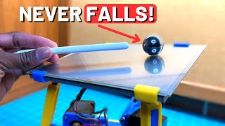
- Simple way how to build self balancing cube with reaction wheels.
No programming knowledge required.
You need a little skills to use ESP32 with an Arduino (or other) IDE. If you not familiar with ESP32 use Arduino nano.
You need a little electronic and soldering skills.
Also needed:
ESP32 or Arduino nano controller,
MPU6050 sensor,
three Nidec 24H brushless motors,
500 mAh 3S1P LiPo battery.
Cube frame is 3D printed.
This project is open source:
github.com/remrc
Last version has an updated balancing point setting procedure.
Important! In this video you can learn how to set the balancing points:
• Reaction wheels for be...
3D print files
www.thingiverse.com/remrc  Наука
Наука


Thanks for sharing! A self balancing cube is now on top of my project list.
Great engineering project that involves mechanical, electrical and software designs. Subscribed!
Thank you for uploading your files! I just ordered the motors and am currently printing the parts for it.
Thank you so much for sharing the code and 3D files!!!
Thank you for sharing the codes and the 3-D print files. Much can be learned from them.
¡Excelente video! Con esta experiencia Ud. estará despertando grandes inquietudes y desafíos a las mentes jóvenes. ¡Lo felicito! 😉👌
This is awesome! Thank you for sharing the code.
Amazing project and very demonstrative video! Kudos !
Thanks!! Finally :D I’ve been waiting for this since the first time I saw your videos :)
Thanks for sharing. GREAT video , I will try to make the device as soon as my parts arrive.
Just finished building mine. Thanks for sharing the files!
Video?
hey, what kind of LiPo battery you have used, whats the operating Voltage of it ?
one of the best project I've seen !
Very nice of you! Thanks for everything!
Thanks so much for sharing this. Incredible :D
Thank you for this video. It helps a lot.
That's sooo cool! the greatest respect to you! thank you for sharing.
Congratulations and many thanks for sharing your project... I am waiting for nidec 24h (1 month with aliexpress). I will add an oled 1306 to show gyro & acc data. I am preparing wheels with 6mm steel balls (with respect to 70g weigth).
With steel balls... Interesting. but it's harder to do than bolts and nuts.
Excellent work.
Thank you for sharing, I like it.
Great design, and nice video!
Fantastic project, well done. The result is very satisfying to see and your video is quite clear and the steps to follow.
I have one question regarding the motors, what made you choose the nidec 24h for this project ?
BLDC motors with controller inside. This make project very simple.
YOU ARE GENIOUS! Chapeau!!!
Got mine up and balancing. Its memorizing.
Hey, neat project! Thanks for making it open source. Do you have any sources available for the theory you used to model the system, or even any general equations that you used? Thanks for your time!
Thanks. I didn't study any theory. I didn't calculate anything. Only some experience and tuning.
I finally got around to building this, Im almost done with the project! I have one question, I emailed you about it. Thanks again for the cool project!
Hey i'm also working on this projet for m'y final test AT school i have did you found som teorical source beacouse i have problem woth my pid i dont fond thé good
Awesome job! busy building one now. Is it at all possible to share the fritzing files and parts used?
nice, i want to make one for a long time, when is the version that jumps alone?
Thanks!
Great project! Can you post a wiring diagram when you get a chance? It would be really helpful
I add schematic to github.
now do the pyramid version. tbh this is crazy mix of engineering and coding / modeling etc i could never do that
Big like ! Respect !
Amazing! Best self-balancing cube I've seen! Could you please give me some reference on where can I Learn more about the method you used for the control method and your tilt estimator algorithm?
I learned by doing a lot of stuff like that...
@@ReMRC That is awesome indeed! Could you give me some explanation on how you estimate the tilt with only one IMU?
@@FranPastorini One is not enough? Of course, can be done better. But this is simple way.
@@ReMRC Yeah It is clearly enough because your cube works awesome with only one IMU! I'm just trying to understand how it works a little bit, I'm pretty new to this kind of project😵💫.
Sorry if I'm being annoying😅 but I was taking a look at your code and This caught my attention, robot_angleX += GyZ * loop_time / 1000 / 65.536; Where does that 65,536 come from?
@@FranPastorini You need to read about reading data from MPU6050 (raw data).
Very cool! Could you make the cube spin by rotating all the reaction wheels at the same time, in the same direction? I'm thinking adding a constant rotation to all the wheels should cancel out everything except a spinning torque...
Like in this video? ruclips.net/video/DshWeMvtPqg/видео.html
@@ReMRC exactly like in the video! It would be amazing to be able to control the spin wirelessly over the web interface.
@@Henrik229 Yes, it would not be difficult to do so.
Thank you very much for sharing your projects!! I am half way building the cube, and It seems like my parts are a bit smaller than the ones I see on the video. Can you please tell me:Did you upload the stl files of an smaller cube? For example, the walls of the cube are 152x152 mm. Also, it seems like you put double nuts.
Smaller? Why do you think? It's the same.
@@ReMRC You are right! My appologies!! I've seen on some of your videos that sometimes you put all the bolts and nuts, and some other you don't. How do you figure it out? Try and error? Or there is any formula to make and approximation function of the total mass?
@@asunasposibolDifferent projects require different weights. E.g. unicycle with Nidec is heavy, so a heavier wheel was needed.
I saw you added a new schematic to github for using an arduino. Does this have any advantages over using an esp32? I also noticed you didn't include any of the red wires in this new schematic. Are those not needed? What were those actually for in the original schematic. Thanks!
Both work the same. About red wires are written on GitHub.
Awesome project! It's there any way to reduce those oscillations when the cube is balancing?
Always possible to do better. But here is a simple way.
Thanks for sharing, this is a great project!I don't know if you have time to share the model of the circuit connection or electrical components
I would like to share, but the circuit connection is only in my brain. :) I'm a little surprised that this is needed, because where is connected ESP32 pins you can see in the source.
I add schematic to github.
Great project indeed!!
The motors are 12v? How do you power them? Directly with the 12v battery or with a step-up regulator? Thanks!!
You see the control board in this video. This is everything. There is no step-up regulator.
The battery is 3p1s so the nominal output voltage is 11.1v that is enough for the motors. The motors are driven by the internal esc
Fantastic project I'm trying to realize it! One question, how many mm are the M4 screws in the reaction wheels?
I use 8mm. But you can also use longer ones (12-16 mm). Flat head bolts. Others will not fit.
Great project and in the process of making one myself! The video and github never mentioned about adding a Bluetooth module when using a arduino Nano, how would I have to connect the Bluetooth module if according exactly to the schematics given in Github and would I have to make any changes to the code if I did? I tried searching if you mentioned it in any of your videos or comments but I couldn't find a answer, sorry if I am asking a repeated question.
Ask google "how to connect bluetooth module to arduino" and you get many answers. Not need to change the code.
Hey great Project ! building one myself currently, which length does the M4 Bolts for the reaction wheel have ? Ist 20mm good ?
I use 8mm. Look carefully at the blue cube. ruclips.net/video/AJQZFHJzwt4/видео.html
Flat head bolts. Others will not fit.
Hi, thank you for sharing such an impressive project!
Can you please provide us with links to trusted (legitimate) online retailers where we can buy the necessary component (e.g. motors, battery, sensor, etc..)?
Thank you in advance!
Trusted? No, I don't have any.
Heyy this is amazing !! I'd like to build a Cubli but probably in aluminum and of greater size for an artistic project.
Is something like 45*45*45 cm conceivable?
What would be the subtle impacts on the engineering side?
I'd like to build the frame in allu to engrave / paint it :)))
Of course it can be 45*45*45 cm. But need other motors...
Hello, amazing proyect!!, I wanted to ask you where did you buy the LiPo battery? I'm having trouble finding one that powers 11.1V, does it work with 3.7V?
Of course not. Only 3 cell battery.
Excellent build REMRC. What length are the screws you use to add weight to the wheels?
You can use 8, 10, 12 mm. All are suitable. In this video is 8 mm.
@@ReMRC Thank you so much for the prompt reply. And the great project.
@@basiltsakalos What length of M3 did you use?
Great project! I am think about modify the cube to a smaller dimension, hence the cube weight and position of the sensor will change. Which part of the code will I need to modify? Thank you very much!
This is a bad idea. Everything should be changed.
Hey mate really great work do you mind showing the wiring diagram a bit more detailed if that’s possible
Hey, I really like your project, want to build myself, which screws and nuts have you used ?
M4 for reaction wheels.
so COOL!
Hi Remi , what transistor did you use to switch the buzzer on and off , One is shown in the schematic but no details as to what is suitable
You can use PN2222.
Thanks for sharing - Question: in the wiring there is a transistor Q1 - which Type is used here ?
You can use PN2222.
Wow such a cool project! :)
I was wondering, what type of connectors do the motors use? It looks like they go from motor connector to female jumper, what is this cable/connector called?
ZH 1.5mm. But they come with motors.
I'm designing a PCB for this, and I was wondering about the transistor you have in the schematic. Which leg is the collector? Is it the one connected to the buzzer or the resistor? Great stuff by the way!
Collector to buzzer. If you use PN2222.
Hi Mark,
Did you finish the PCB at the end? And if yes, would you be willing to share it ? :)
Hey, have you finished the PCB for this project ? would like to buy it if possible, this would really help me as i am a student
incredible
Hey great project!! I was wondering if u could recommend some alternative motors incase these aren't available
it available on aliexpress and ebay.
@@ReMRC I'm from India so it's a tad bit difficult for me to acquire them here
In what way would it affect the performance if the reaction wheels weigh more or less than the 70g . I assumed a heavier wheel would have more inertia and control the cube easier
More inertia, but also more total weight to control (cube weight).
This was fun to do. I'm thinking of customizing my cube. Two questions:
How much weight would you say is too much weight for the whole cube? Does the pointiness of the corner play a role, would a rounded corner be fine?
The higher weight, the worse. The corners can be rounded, it won't make a difference.
@Nick did you manage to solve the problem with the motors running at full speed?
@@vitrola_exe :) There is no such problem. You probably didn't watch the videos carefully (both).
I wonder if you put a flat surface on one of the corners of the cube If you could stack them
Danke!
What a brilliant project. I would like to rebuild this cube. But I'm missing the specification of the transistor Q1 (in the video min. 4:56)
Have I overlooked something?
Many thanks for the help!
Lots of confusion with that transistor. :) In video I say "transistor and two resistors". In schematic - one resistor. This is because I use mosfet. You can use PN2222 or something similar (n-p-n).
@@ReMRC Thank you for the fast answer. I have ordered the first parts and I hope that I will be able to realize this amazing project.
Check! Last weekend I managed to balance the cube.
Many thanks for the great instructions and the great support you provide here! - like more of it :-)
@@tinalina1808 any special tips not mentioned elsewhere?
What do you mean in the video is that the 12.6V voltage is divided into 3V proportionally through the resistor, because of the limitation of the port measurement voltage, and then converted to the actual voltage through the code?
No, I am measuring the battery voltage for over discharge protect. This requires a simple divider of two resistors.
I didn't see mention what the voltage the motors are powered from. Are they getting power from the battery or the 5v regulator?
Of course, power from the battery.
Dear ReM-RC, looking at your code I got the following question, what are these specific offsets for?
float offsetx= -0.99, offsetY = -3.43
float offsetx2= -31.24, offsetY2 = -19.05
float offsetx3= 30.4, offsetY3 = -19.21
float offsetx4= 0.17, offsetY4 = 35.9
Didn't you watch the video? There is about it.
I printed all the parts, how do I arrange the nuts, is there any balancing tactic?
thanks for the project!
Bolts and nuts you can arrange as you prefer. Only symmetric important...
ReM-RC Love this video. I 3D printed parts, wired everything up with an Arduino Nano but I seem to be tripped up on the calibration set points, no motor spin and all my angles are wrong when sending the C+/- commands? Pretty sure it is something simple, any pointers? Thanks!
Email me what angles prints when you send c-. You can find the email on RUclips "About".
@@ReMRC Thank you for such a quick response, email sent.
hey Great Project ! i currently working on my own and wanted to ask you if you could provide the specific Model Numbers for the Nidec 24H Motors, as there are a few models, also for the LiPo, which Operating Voltage does it have ?
Best regards
LiPo 11,1V, Nidec 24H404H160.
@@ReMRC thanks for the quick response ! i bought a similar modell of the Nidec 24H, should hopefully still work, is there any important limitations / details for choosing the right LiPo (except the votage), for example the weight or dimensions?
@@tayeki8876 Small battery - 450-500 mAh.
I love the content I just hate reading so much. I’m a better listener than I am a reader. Haha.
If I use different material (which means different weight) to build the cube, which part of code I need to adjust? Or the material doesn’t matter? Thanks for making this video and make the project open source!
Material shouldn't matter as long as wheels are same 70 g and motors are the same. That's how I understand but I can be wrong
@@OSNX Thanks! I'd like to ask that in "functions.ino", line91, robot_angleX += GyZ * loop_time / 1000 / 65.536, why using the figure 65.536?
The total weight of the cube matters also.
@@ReMRC Got it. I am wondering that how I can modify the code.🥲Thanks!
Hey really Great Project !! i am currently building one myself, my question: in the schematics of the ESP32 Version you used a 35V 100nF Ceramic capacitor, but in the Arduino Nano Version you used a 16 V 100nF one, could i use the 35V from the ESP32 Version in place of the 16V one in the Arduino Nano version? or would it create any problems ?
best regards :)
Of course 16V is enough.
Is it correct that you have the encoder +ve connection to 3.3v ? The datasheet for the motors says 5v.
(I know you aren't actually using the encoders but I wanted to wire it up properly just in case you decide to use them)
A very fair question. I tried it - the encoders work perfectly from 3.3V. I use them in other projects. e.g. here ruclips.net/video/AV_gpJPhp-s/видео.html
In the esp32 schematic, Q1 would be PN2222 or 2N2222?
With the 2N2222 transistor is Emitter > GND, Collector > Buzzer, Base > 6.8K resistor?
And in the case of the PN2222 it is Emitter > Buzzer, Collector > 6.8K resistor, Base > GND?
Strange problems with this transistor... startingelectronics.org/tutorials/arduino/modules/active-buzzer/arduino-active-buzzer-circuit.png
Hi I am collecting all the parts to start building! already printing the parts. However. I see in your video that you are using a transistor and two resistors for the buzzer but they are not in the electrical drawing that you made. also i see a small led that is not documented.
What are the specifications of the two resistors and transistors and how do they fit in the electrical diagram?
Is the transistor underneath the buzzer the mosfet? I ordered a PN2222 transistor.
In video I am talking about a buzzer transistor. Yes, I use mosfet (why - long explanation). You can use PN2222. It is in the schematic. A small led only shows the connected battery.
@@ReMRC Thank you for the swift response! and the two extra resistors? there are 5 in de video. three in the schematic.
@@7423Sin Follow the schematic. I did a little differently.
@@ReMRC check! Started the build. Thank you for the response 👍 will post on thingiverse once it's completed
How much V does the LiPo have? 11,1V? 14,8V?
And what voltage do you measure that you have to input into the source. The voltage of the battery in its full state?
And the 5V regulator: Is 800mAh output enough?
3S LiPo. I measure battery voltage. When voltage drops to 9.5V buzzer beeps. 5V 800mAh enough. Need much less.
What size screws are the motor and circuit board mounts? Thanks.
Motor M3x6mm, circuit board M2x10mm.
Hey buddy, I’ve decided to build this project but I’m not exactly sure where is the best place to find those motors at least in Europe. Know of any alternative product to replacement?
I don't know where to get it in Europe. But I see no problem buying on ebay or aliexpress. There are no alternatives for such motors.
Would you mind sharing the brand of the battery you used? I can find a lot of similar batteries, but they appear to be much bigger than the one you use and I am afraid they won't fit the slot.
I am also not able to find the Nidec motors anywhere. Is there a known alternative for them?
Bigger? No... 500mAh 3S1P LiPo. TURNIGY, Gens ACE, and many others. Nidec motors you can buy on ebay, aliexpess.
@@ReMRC yeah, I was avoiding buying the motors on Aliexpress because the shipping costs are higher than the price of the motors. Anyway, I could find everything there. Thanks.
@@ReMRC are there any key words we can search as alternatives to the nidec motors since ebay and ali express are not viable options in my region
@ReM-RC is it possible to get the arduino to have an output to light up an led upon it balancing ? if so which part should I add my if conditional
Of course this is easy. But I don't have a cube with an Arduino nano right now, so I can't do that.
@@ReMRC hi rem its been a while, i working on the cube again i didnt do the light anymore, my cube(s) work great. so happy i made another, but i wanted to 3d print a shell to hide the electronics, now the whole thing is too heavy and it keep falling after 3 seconds. are there ways to get around this issue? thanks in advance and looking forward to your next balancing video haha
@@jeromewong9945 Heavy? Photo? Video?
@@ReMRC can I email you the photos instead
@@jeromewong9945 You can find the email on RUclips "About".
good night my friend, beautiful project, but a question: would you sell it complete? I'm having trouble finding some components
I don't sell them... And components are often used. What can't be found?
@@ReMRCcant get the NIDEC 24H motors
What alternative of Nidec 24h can be used to run it perfectly?
In this design only Nidec 24H.
hi great project just ordering parts and slicing parts for printing, have any shematics for the wiring of the breadboard shown in video, many thanks
I don't have any schematic. It's really simple. Where is connected ESP32 pins you can see in the source. But I get a lot of questions about schematic, maybe I need draw it...
@@ReMRC thanks for the shematic, great work last question what value is "Q1" on the shematic its connected to Buz1 and R4. thanks
@@wayneo559PN2222 or something similar. N-P-N transistor.
one more question , is the transistor connected Emitter > GND , Collector > Buzzer , Base > 6.8K Resistor ?
Yes, correct.
@@ReMRC Thank you , I will start building now
Like your videos and the cube is top. Wath are the dimensions of the square ?
15x15x15 cm
Great project! Can you please let me the size of prototyping PCB? 50x70mm?
Yes, 50x70mm.
hello, great project, I plan to make the version with the esp32. I wanted a precision concerning the transistor pn2222, on your plan github esp32 concerning Q1pn2222 B=? C=? E=? because the wiring of Q1 for the arduino version indicates E=gnd C=Bz1 B= R4. so I have a doubt for the Q1 esp32 version. thank you and nice job
Yes, for PN2222: E=GND, C=Bz1, B=R4. I use different transistor...
@@ReMRC thank you
hello, I just finished mine with an esp32 with a pcb, different stl for gluing and different and much cheaper nidec. I have to paint the chassis, I'll post a video in two or three days.
@@conetablebe Cheaper nidec? I'm waiting for the video.
Hi. tell me in what order to connect: DIR*, PWM*, PWM*_CH and "start/stop", "forward and revers", "signal speed regulation"? Вo we need a signal from encoder "A" or "B"?
I added a schematic to github.
Is it possible to cut the frame out of aluminum or would that throw off the balance?
Maybe yes. But I don't know how much heavier aluminum would be.
Hey, we are french people and we have a question: What is the PCB prototype what is his function. Thank you for amazing explanation!😁
I did not understand the question. Sorry.
For a beginner, how difficult would it be to develop the control loops? I have a background with some control experience but not mechatronics.
It is impossible to answer difficult or not... It's different for everyone.
does any code need to be added to connect the arduino nano via bluetooth using the HC-05 attachment?
No, the same data as via USB.
This is a great job, I have a small question, is it possible to apply this code to another microcontroller, arduino nano?
No. But for two axis balancing I use an Arduino, it’s simpler.
@@ReMRC As I understand it, it's all because of the PWM signal, since the Arduino does not have enough ports?
Can you recommend books or a manual to better understand how to program a microcontroller and sensors?)
@@user-fy9ry1qe3w No, this video is about self balancing cube, but not about programming learning. Sorry.
@@ReMRC thankyou
I succeeded
Please can you provide the link to where you purchased the motors?
I've been looking now - there are a lot of these motors on ebay.
I am attempting to get the offset values in each position as show in the video, but my X and Y angle is -45, 45. Maybe my MPU is not functioning correctly. Any ideas on how to solve this?
You should try any example of reading MPU6050 data with ESP32. Once the data is successfully retrieved, it will work with the cube as well.
This is not a problem with my program.
Great Idea. What is the weight of your Cube?
930 g.
Hi there! I've got this setup but after uploading the code, connecting the battery and connecting via bluetooth I am unable to open the Serial Monitor because it says the Port is busy. Any idea why this might be happening?
Port busy - this is a PC problem. Maybe you are trying to use the wrong port.
To my previous question, I mesured the sizes and you used 4mm, 3mm and 2mm, are these okay or did you use some more?
Yes, it is easy to count while watching the video.
@@ReMRC Thanks!
started ordering parts tonight!! 1 thing.. what size bolts and screw wire used ? don't you have a Patreon?!
4mm bolts on reaction wheels. Motor mounts - 3mm. I don't have a Patreon. But if you want to thank you can click "Super thanks" after the video.
@@ReMRC 4mm wide or long? wat size? M4x4? M4x3? M5x12?
@@7423Sin M4x10 or M4x12
@@ReMRC perfect! Thanks buddy 👍
love your project im building it currently and there is a problem with the buzzer it keeps on buzzing for some reason can you help me on this
If you use PN2222, check the connection. startingelectronics.org/tutorials/arduino/modules/active-buzzer/arduino-active-buzzer-circuit.png
Printing it right now. Is there a possibility to Code it that it can stand up by itself like Cubli? Would be amazing!!! 🤩
No, this is simple way, how to build self balancing cube. Cubli is much more complicated. One of its motors costs more than all the parts of this cube. :) Not just the code difference.
@@ReMRC Thx for the answer. Parts are ordered, Printing parts are awesome. Hope assembly isn`t so hard. Wish me luck ;)
Got these 12pin motors working. I have discovered that the start/stop pin needs 12v or they remain off. It all looks good now but the motors are turning in the wrong direction. Can that easily be changed in the code? If so could you help me with where cheers
The seller describes these motors in a strange way. PWM from 16000 to 26000 Hz, but he contradicts himself:
1000 HZ 150 rpm, 10000 HZ 1500 rpm, 12,000 HZ 1,800 rpm...
It seems to me that he himself does not know. :)
I tested the motors with the "motors_test" programming and everything went ok. Each motor rotating clockwise and counterclockwise.
With the other programming I calibrated the points normally. When I place it on one of the edges, the motor referring to the edge starts to rotate at maximum speed. And at the vertex the three motors run at maximum turning on the beep. Do you know what it could be? Perhaps the value of k1?
Did you watch the second video?
@@ReMRC Yes, I watched it, I'm finding it strange that the 3 motors rotate only in one direction with maximum speed.
@@vitrola_exe No, you are doing something wrong. You can send me a video, maybe I can help.