
HTML-код
- Опубликовано: 17 июл 2021
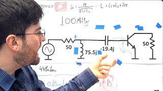
- This video shows how to measure the input impedance and gain of a small-signal RF amplifier - including the use of an attenuator to keep the amp in it's linear range and also to not overdrive the NanoVNA. This stems from a recent conversation with Bill N0CQR (SolderSmoke podcast). The amplifier featured is a "Termination Insensitive Amplifier" or TIA that is described in paper by Wes Hayward (W7ZOI) and Bob Kopski (K3NHI) - see links below:
Soldersmoke blog:
soldersmoke.blogspot.com/
Wes's webpage: w7zoi.net/
The TIA paper: w7zoi.net/bidirectional_matche...
Papers on the theory and models of transistor amps:
w7zoi.net/fba_with_simple_mode...
w7zoi.net/transistor_models_an...  Наука
Наука


Brilliant, simply brilliant. No more rules of thumb, no more wet fingers in the air. Now we amateurs can do what scientists and engineers do...MEASURE!
I watched some of your intro videos on the NanoVNA last evening and was laying in bed wondering if the NanoVNA could test some preamps and then thought I'll likely need some attenuators. Then I stumble across this video doing just that.
I really wish the NanoVNA was around 20 years ago when I was in college. I might have done much better in my microwave circuits class. I'm just realizing that I did a 3 year telecom course and never got hands on with a VNA or a spectrum analyzer. Now 20 years later I feel like I'm finally getting it. Had a similar experience the first time I seen AT&T's similarities of wave behavior like 15 years ago. I feel like college gave me a really good foundation in physics and math, but the radio electronics end of things was pretty weak. I've also never really worked in the field. Spent the first 10 years(starting from 17 before college) of my career working in AV doing sound, lighting and video. These days I do science center exhibit design, fabrication and repair. I've been a ham since I was 16(25 years ago). I keep coming back to the hobby and having new breakthroughs in understanding. Like the first time I seen SSB on the SDR waterfall, modulation suddenly made so much more sense.
Amazing, I'm doning electronics my story is the same.
Glad to see this precise and systematic tutorial although I know it from my last job. As a VNA metrology engineer, I can say everything is correct and done with respect to NanoVNA limitations.
Thank you for the confirmation!
My father was an Environmental Test Engineer at Tektronix when he died in 1974. Your speech reminds me of how he use to try and explain questions I might have. Great video and great podcast on the Amphour
Thank you Alan. This helps so much. Armed with your info we can all now use the NanoVNA to accurately measure circuit impedances. This will be an enormous help for those of us who routinely take bits and pieces of circuitry from multiple sources and try to put them together into working rigs. Your video and the NanoVNA will remove the Z guess work. Thanks again and 73 Bill
@SolderSmoke Bill - you nailed it! I'm one of the folks that your and Alan's back and forth has been helping - thanks to both of you! 73
I heard "N2CQR", oh! That's Bill Meara of Solder Smoke!
Very helpful info, Alan, especially your explanation of the 13 dB attenuator.
Very useful technique using an attenuator. Will be using that to check a 2N5109 amp driving a crystal filter.
OM W2AEW at the workbench is some of the best content on RUclips, IMHBCO.
Agreed 100% He is an excellent presenter. He presents info in concise detail that is easy to understand.
Thanks again for your great videos on use of test equipment. 73's Dan ~ KC4GO
There is so much to learn from your attentiveness to every small detail, I will be the first to admit I am always in hurry and missing a lot in the process. Well, maybe in time, who knows
Thanks for a awesome video again, Alan
I am gonna download all your vids as a reference, i was fumbling around with an active probe trying to caracterise it and failed for just about all the reasons you mentioned here 😄
Thank you Alan 👍🏻
You’re a freaking genius, how the hell did you figure it was the VNA out amplitude. And how did you figure the amps input limit. I’m 59 yrs old I wish I had your brain. Great video 👍. I have a nanoVNA and I don’t remember why I bought it hahaha.
Your channel is incredibly educational and you explain everything in a way even that even a lay person can follow along. Great content as always.
Feel so lucky for hitting this jewel channel on RF engineering. Learned so much from Alan. Have shared with my circle.
i did stop the video to figure out which is the reason of messy measurements...
no chance !
hat off to your knowledge
Great Video Alan! (as always!)
I normally would have caught that because any time I do an analysis on something, I'm always cognizant of how much signal to put into beforehand.
This really true for direct-coupled amplifiers where you can pin-one to the 'rails' and blow things up!
In saying that, I can see where you would intuitively-assume that it's output would not be real high (i.e. tiny-box = tiny-signal!).
For the RF, I'm at the point of always first figuring out how much attenuation I can insert without compromising my measurements--good practice...
Great example of using different instrument to validate amp functioning correctly and rapidly moving on to VNA . Looks so easy but requires rock solid understanding of fundamentals , a broad base of knowledge and years of experience to know how to join the dots . Thanks again
Thanks for the video tutorial, Alan.
So many would have been tripped up by this lesser known fact of NanoVNAs when trying to measure amp or similar parameters.
God bless!
I ran this same test on my H4 for a HB 2M preamp. I had to severely attenuate the vna output. Really like your videos. I also ran the preamp through the Siglent SSA3021X, and the nano compared very favorably...keep up the good work.
73
Glen K4KV
Thank you Alan for an excellent video. Also for giving me a D'OH moment... a while ago I bought a Nano to help with designing a front end for a 433MHz remote control IC which has a wierd-ass input Z. After a lot of calculations and prototype it didn't work out. Now I realise the back to back input ESD protection diodes might have had something to do with it! 😖
Very useful tips! As a beginner in this RF magic it would take me a while to understand what am I doing wrong 😁
That was great! Thank-you!
I'm trying to teach myself about some of these RF radio frequency and IF intermediate frequency concepts. I'd like to be able to easily and accurately determine stage gain in radios and televisions as well as test instruments and AF audio frequency as well.
I'm a hobbyist at middle age trying to learnand master many things I failed to when I was younger. Thanks again and God Bless.
An OUTSTANDING video!! I had not considered the need for an attenuator on my nano VNA in some apps. Though, I use them all of the time on my spectrum analyzers. One of those Ah-Ha moments for me !
Thanks es 73
Glenn
SC
Very simple, direct and easy to understand!! Thanks! :)
Alan another wonderful learning lesson. Thank you so much. Take care 73
This video comes at an opportune moment, as I'm playing with one of these little BGA2866 MMIC amplifiers. The S21 gain measurement on the NanoVNA is also invalid when the signal distorts. Adding attenuation changed the gain figure from 11dB to 18dB on this test board. Thanks!
Thanks for the demo! I still need to get one of those VNA's. Looks very handy. :)
Hello Alan, Your videos take me back to that sense of wonder I has with my first arrl handbooks when I was a kid. I hope you are considering publishing a workbook or series of reference workbooks at some point as your style is effective and enjoyable.
Maybe I'll write a book when I retire - no time now!
Up to now, i didn´t realise that NanoVNA limitations regarding output level. tnx!
Sir, as I have said many times, you're an inspiration, and I wait for ur videos, Thank you
the subject is 100% spot on :D cant wait to watch it!
That was epic. Keep 'em coming!
Great video. An attenuator reduces the dynamic range of the VNA, so I've used a directional coupler to get a little less noise. You're at the upper end of dynamic range, so not a concern in this case.
Great stuff - thanks once again for a very informative video !
Thank you! This is an excellent video, I learned a lot.
very interesting and very good explanation OM
awesome video as always.
As always, learned a lot. Thanks.
Another great tutorial, thank you Alan
Great Video, Very good information. Thanks for all you do.
Oh I just realized what the guitar pick is for in my NanoVNA kit! hahaha! The stylus works just fine though.
The same here. Now I feel sheepish.
I would like to give you my sincere praise and support with all my heart and sincerity for your channel, who has been working hard for your dream, to gradually develop and develop into a very large channel. I feel that it is a video that subscribers will like. I don't. It's so good. I hope that everyone will be happy while watching your video. Your videos are of really good quality and the best. I really admire you. I think I'm being possessed by the algorithm. I hope that everyone is happy and everyone lives in a world without a mask, that everyone is happy and that there are no unhappiness. Thank you for your video and I hope that your channel will be filled with good things in the future. I really fell in love with your video. .I personally like it very much. I hope that you will only walk on the flowery path from now on as much as you have worked hard. Thank you for the space-like algorithm that made it possible to see good videos
Yep, good workaround for this situation. I have played around with 2N3904's with some negative feedback also and they are amazing performers for such an ordinary transistor you can get cheaply anywhere!
Much better than a CK-722.
@@gordonwelcher9598 Yep. I remember them well!
You have a clear mind, bless you.
Super explanation, thanks.
Thanks for this Alan, now it all makes sense 73 Bob
Watched before I left to office, a good start of a day.
Awesome, thank you for teaching! :)
Thanks for the education. That would have driven me bonkers. Cheers.
Excellent video. A check for overdriving the input will be something I’ll always consider in the future.
But the star of the show was the HP15C calculator! I wonder what the kids are using in school today?
Probably a calculator app on their smartphone! (I have a HP15C emulator on my iPhone for when I need a calculator away from home).
Allen.... Always the best... 👍👍👍👍
Great video! Simple!
Very informative, thank you so much
Very good info. Thanks!
Thank you for this!
Thank you.
Enjoyed the video. N0QFT
Thanks, so far I've only measured antennas using 1 port. (VSWR or s11)
This is awesome, Alan. I have been fretting over this very thing for the past few days and was slowly working out a process to do it. I'd even bought, a couple months ago, a TO-72 HP 11858A & 11600B transistor fixture for my vintage HP8753 which allows you to insert and bias bjt's in the 3 different amplifier configurations. How would you measure output impedance? Specifically, how would you do this for tube amps? or high power LDMOS amps? I'm not the sort of person that just accepts that you do xyz (i.e use a 1:9 output impedance transformer as rote for an LDMOS part) because everyone else does it that way :)
Can you consider doing an episode on amplifier stability and oscillations? Things like k factor, u1, and viewing oscillations on a spectrum analyzer. Thanks. I appreciate your videos a lot
Very nice , like always it is !
Excellent!
Can you do an additional video and drive this amp into compression observing S21 and the phase in particular. I would love to see what phase compression looks like.
Nice demo, i like your videos thanks for share.
Any video by you explaining the function of every component used in the 433 MHz transmitter and receiver RF circuit, explaining working of the both the RF transmitter and receiver circuit
Thank you teacher 🙂
Thanks a lot, sir!
Another great oresentation.
I NEVER HAD THE TIME TO SPEC THE OUTPUT LEVEL, AND NOTICE THE EFFECT IT HAD ON INPUT LEVEL SIGNALS. THE NE602 MIXERS NEED TO BE LOOKED AT IN MORE DETAIL, MAYBE THERE IS A WAY TO ADD A CIRCUIT TO DO THIS VERY SAME TASK, BUT ALLOWING IT TO BE SWITCHABLE AS WELL.
WHEN YOUR BOX OF TOYS DOES NOT HAVE SUCH ATTENUATORS, YOU ARE FORCED TO ADD EXTRAS, BUT THAT REALLY CREATES A MESSY TEST BED.
3dB, and 10 dB PADS I HAVE, NOT THE INTERMEDIATES. GUESS I WILL BEGIN ACQUIRING THESE AS WELL. THANKS!
no need to shout here
Beautiful.
Amazing video. Was thinking of trying this same thing two months ago. Great tip about the nonlinear effects. The amplifier has to be turned on (biased) to make this measurement? Do you need a DC block to protect the NanoVNA?
Yes, it has to be biased because the feedback helps to set the impedance. A DC block is needed, and is included in the design.
Loved it
Great video to learn from. One (maybe stupid) question: is the tested amplifier under power when you test the impedance and gain, I.e. during the S11 and S21 tests?
Yes, it was powered up.
Very nicely presented and clear. (a) Any caveats when measuring the output impedance looking backwards into the amplifier output? (b) Which firmware are you using in this video for the H4? Mine does not seem to have the "401 points" on the bottom..
As long as the output is AC coupled, then simply terminate the input and measure S11 on the output. I am currently running 1.0.39 from Dislord (see video #320: ruclips.net/video/NcXzITPPTyA/видео.html) on my H4.
Brilliant. Thank you sir! 73 W6MGV
A NanoSA as well as having the Nano VNA is a great combination to have.
Hi Alan, I think this is your most recent video, so I'd like to reach out and ask you to set up an experiment that's right up your alley but I haven't seen you do it. It applies largely to PCB design and I think it was Rick Hartley that mentioned it but it's pretty spectacular and very simple to to.
If I have this right (and I may not!) the idea is you get a loop of coax - maybe a few metres/yards long (I'm European so I use metric) and insert an ammeter in the ground shield some where at the top of the loop.
Then you "short" the shield at each end with a short piece of wire - and you've probably guessed - put another ammeter in that short run.
Rick points out (and I believe him but I'd love to see this done) that at DC, the current all flows in the short return path *but* as the frequency increases, and he says the effect starts at audio frequencies, the current flowing in the "direct" path to ground begins to diminish and increases in the much longer loop.
Rick explains this is because as the frequency increases the energy, which is travelling along the dielectric as a magnetic and electrical field (again, I might be wrong here) starts to "hug" - my word - the shields on the coaxial line.
I can do this at home with my own paltry "free shipping from China with a counterfeit XR2206" equipment ROFLOL but you're a great teacher and with your skills and superb equipment you could demonstrate this to a far wider audience than Rick or Eric Bogatin are able to reach!
You've heard the addage that "current always takes the path of least resistance". We'll that's not the most accurate way to state that... It would be more accurate to say that current always takes the path of least *impedance*. For return currents flowing in a ground path, the "least impedance" translates mainly to "least inductance" as the frequency increases. Inductance is minimized when the "loop area" between the forward path of the current (center of the coax in your example) and the ground/shield return path is minimized. Thus, the image/return currents "hug" the region closest to the forward current path. I talk a bit about this in my video on bypass capacitors (ruclips.net/video/9EaTdc2mr34/видео.html)
@@w2aew Well blow me over with a whisper! :) Somehow I missed that one - probably (cough) bypassed (cough) it because I already knew about placing small caps near to the VCC/VDD rails on my ICs. I've been doing this like a trained monkey since I was a kid with no real appreciation of why.
I've been working my way through your stuff and I wish I'd had teachers with your skill at explaining stuff when I was learning back in the 1970s. It's hard to explain the debt of gratitude I feel for all your work!
I'm still a little vague on this transmission line stuff since I tend to associate it with RF stuff that I don't personally work with. Of course, as you've pointed out here, the fast edges we're creating with modern chips (heck, I can recall near-chip bypasses back on early CMOS chips) produce masses of RF harmonics off into the multiple Ghz just by the switch time.
I forget if it was Rick Hartley or Eric Bogatin who described the experiment but (if you do care to recreate it), I believe the idea was to put an ammeter in the "short" side and another into the long loop. As the fundamental sine wave is swept up into the high audio frequencies and beyond (if I've grasped what they were saying) the current - continues to follow the path of least impedance, so the current in the dead short drops away while the current in the (measurably) longer DC path starts to increase.
Presumably this would require the sort of bench gear that many of us don't have as DVMs won't be able to measure AC currents accurately.
I think it was Paul at EEBlog who traced around a ground plane with a fairly high end current probe attached to a Tec scope and demonstrated how signals propagated through the copper.
I know this is pretty basic stuff to some but my poor brain opened the lid of my noggin and a white flag popped out. ;)
Apologies for the humour, it's the shortest path to describe my ignorance and astonishment at these wonderful demonstrations.
Thank you again.
I have watched at least 3/4 of your videos and love your content and explanations. Not quite the place to ask, but I don't know how else to get a message to you; Is there any way to do simple transformer/inductor ring testing using an oscilloscope? I know you can buy specific testers, but for occasional use I wondered if some simple oscillator could be used to see if a coil was shorted on an oscilloscope? All internet searching has failed to get me any ideas. Any info would be really great. Seems like something others may also want. Please keep up your great content.
Have you watched these two videos?
ruclips.net/video/74fz9iwZ_sM/видео.html
ruclips.net/video/Ff5xOENID7w/видео.html
Great video yet again - but where on earth did you get a 13dB fixed attenuator!?
LOL - not sure where it came from, it's been in my accessory box for a while...
This looks like a great tool. Do you think it’s possible to use this tool to help create a homemade precision 50 ohm BNC cable like Tek’s older ones used in calibrating their 70’s and 80’s plugins?
Great video! Can you please show us how to check that the output impedance of the amplifier is also 50 ohms?
You would simply terminate the input of the amplifier, and then connect the output to CH0 and run a S11. But, also you can see this basically from inspection. An emitter follower has a very low output impedance (basically 0.026/Ic), in this case just a few ohms. Then, there is a 47ohm in series - so it's basically very close to 50 ohms.
Newer versions of DisLords firmware have an option to reduce the output, not sure what the minimum is thou.
Thanks for sharing w2aew!
Does this mean that I have to use a 13 db just to check the input tune of my Mini-Ball TL60 60 watt one transistor amplifier?
The problem is that the SWR is 3.1 to 1 with the amp on. It is putting out 50 watts with 1 watt in.
I suspect that it is tuned to the center of the 10 meter band. In fact my Nano VNA actually shows that it resonates at 28.500 MHz if I sweep the input of the amp
and has an SWR of 2.82.
I'd like to tune it to 11 meter and get the SWR down as low as possible.
When I first saw it, I was bit surprised that this design does not start to self-resonate, given that the bandwidth is quite high for a 2N3904 based design. What is the phase shift of one amplifier path at unity gain?
Thanks for your really outstanding videos! I've got a NanoVNA SAA2. There's no isolation or through nenu during calibration. Guess it mean it's taken care of? Thanks. 73
Some models don't have the ISOLATION cal, but it should have the Through Cal.
Thanks Alan! That's really helpful. 73 Nick M0NTV
Hello Alan, thank you for the video. I have a question about adding an attenuator at at the nanovna output. Wouldn't that cause an accuracy problem with the S11 measurement?
The affect of the attenuator can be calibrated out. However, since the signal injected to DUT is attenuate, and the reflected signal is also attenuated, there will be some additional uncertainty in the measurement - especially for DUTs with a good S11 (low reflections).
I know that Bob K he doesn’t do amateur radio but is knee deep in the free flight and rc airplane arena still. He is in the same rc club I belong too Keystone rc Club
Nice video as always.
Do you have a video about TL072/074 JFET input Op-Amp on how to properly use them and its performance/behaviour and their differences between LM324/4558? If non yet, is it possible to feature it in one of your next video please? Thank you and more power.
They are quite different. The LM324 is specified for operation from 3V to 32V supplies, while the TL072 is rated for 4.5 to 40V supplies. The LM324 input common mode includes the negative supply rail (but not the positive supply rail). The TL072 is just the opposite - input common mode range includes the positive supply rail, but not the negative supply rail. The TL072 output can swing fairly close to both rails (with light loading), while the LM324 can only get up to 1.5V below the positive rail. These are just a few of big differences...
@@w2aew Thank you very much for the quick response.
I bought last year a TL074 with ST brand(no original) and last month with another brand(no original) but they're both from China. I wondering why the newer one behaves differently, lots of noise and early clipping. I'm thinking I might have some errors. I'm thinking if there are proper ways of using JFET input Op-Amps though my ST brand workes fine on the same circuit. I know the second purchased with another brand are not original for sure but same with my ST brand that works. Maybe I was faked(?)
Thanks.
@@JB-20 It sounds like you may have received fake/counterfeit ones. Also, not that not all JFET op amps have the same specifications - so always check the datasheet. Of course, if you get fake ones, all bets are off...
@@w2aew Ok, this clears everything. Thanks a lot.
Very insightful. Never seen a bidirectional amp like that.
One question. How would you measure the output impedance of an amplifier?
Terminate the input, connect the output to CH0 and measure S11.
@@w2aew thank you. I assumed there was more to it. But it really is as simple as that I guess.
a video for measuring output impedance in RF systems
Incredible video as always. I am using a Nanovna in order to check the input impedance of a transceiver IC used for an RF-433 Mhz module. The tranceiver IC has an LNA stage this is why I need to use a 30dB attenuator in the CH0 so that the IC's input stage amplifier will not get saturated(exactly as your video). The problem is that when I try to calibrate the nanoVNA using the 30dB attenuator the results I get are very very noisy. It seems that the impedance values in the smith chart are all over the place and I cannot understand why this happens. I have tried a second nanoVNA with no better results.
This is to be expected, unfortunately. Even high performance lab grade VNAs will be noisy with a 30dB attenuator inline, expecially in CH0. Think of it this way - the signal generated out of CH0 is attenuated by 30dB (1000x) before going to the LNA input. Any reflected signal from the LNA will return through the same 30dB attenuator, making it even smaller yet. So, for a device with a good return loss, the reflected signal will very small, and will be reduced by another 30dB before being measured by the VNA. The only things that may help are the use of averaging and a lower RBW (if your unit has the ability to adjust the RBW or measurement BW).
Oh understood!!! Thank you very much Alan! You are always to the point!
Inquiring minds need to know! Is there anything significant about the 13dB attenuator? It seems very "random"? Great video showing one of the many "gotcha"s in electronics!
As described in the video - it drops the level to an acceptable level, and it’s approximately equal to the amplifier gain
👍
Very enlightening, sir. I'm building that exact W7ZOI amplifier.
If you would be so kind as to offer me some advice, I would appreciate it.
I'd like to test the impedance of a mixer oscillator input using diodes with 300-500mV fwd voltage.
I'm guessing the Nano-VNA with 600mV should do the trick?
73 and thanks for everything you do
For a typical diode ring double balanced mixer, the LO port will typically NOT have a nice, well controlled impedance. The function of this port is to quickly and fully commutate the diodes. When this happens, then RF/IF ports should reflect the impedance at the other end, since the diode is making the connection from the IF to RF (or vice versa). Testing the IF or RF ports without a) terminating the undriven port, and b) properly driving the LO port, will lead to incorrect results.
@@w2aew Thank you!
Hello Sir...I just run the same experiment, and it works using the 20dB attenuator, the TIA gain was around 23dB.
BUT the nanoVNA graph show wierd pattern when calibrated using the 30dB or 40dB attenuator. I dont know why ?
I will appreciate some guide lines for tunning NFC PCB antenna with Frequency 13.56 MHZ
Greetings....
Is there not a way to set output levels using Dislords software during calibration ? Was that added later, after this video ? I looked at menu, have not done any measurements, Dislord version 1.2.20 - NanoVNA-H 4.
I'll have to update my firmware to see - not sure how much it can be adjusted.
Thankyou.
Possible use less output Power (after reset go to Calibration->Power) in this fw Power auto use 8mA output in this range, so try reduce Power to 2mA, and after this made calibration.
Thanks - not all firmware versions give you the option of adjusting the power, so that's why I didn't mention it.
Question: why don't you calibrate at the end of your adapter that connects to your amplifier and the end of the cable connecting to your amplifier?
I didn't calibrate at the end of the adapter because I don't have a set of female open/short/load standards. Not worried about it though, since the phase shift through that short adapter was not significant at the operating frequency of the amp.
@@w2aew Thanks! That makes sense.
so where did you get the idea to use a 13db attinuator, was it from the determined gain of the circuit?
Yes, based on the gain of the amplifier