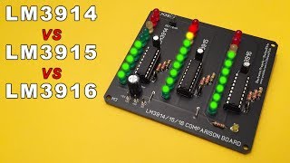
LM3914 vs LM3915 vs LM3916 - Differences and Uses + Electric diagram

HTML-код
- Опубликовано: 15 окт 2024
- ✅ Subscribe to my RUclips channel It's FREE!
PCB: • LM3914 vs LM3915 vs LM...
In this video, the three ICs (LM3914 - LM3915 - LM3916) are compared... and what will be the best to realize a Vu-Meter?
The main differences between these ICs are:
• The LM3914 is a linear display.
• The LM3915 is a 3db increments logarithmic display.
• The LM3916 is a VU-Meter display. (-20 to +3db)
And from this we deduce that:
The LM3914 is typically used to create a voltage display using 10 LEDs, while the LM3915 and LM3916 are typically used to display audio signal using 10 LEDs... And now that I've explained everything to you, SUBSCRIBE =)
► My best Vu-Meter on Breadboard: • Vu-Meter with 20 LEDs ...
► More videos: / stefano91ste
WARNING: This video is only for demonstration, i do not take any responsibility for damage to things, people or animals.
► Music "Smile" by Vexento: / vexento
#LM3914 #LM3915 #LM3916


PLEASE Like and share this video =)
circuit diagram????????
@@hunzai369 look at 2:12
Thank you so much, i've been looking for a circuit like this one for the past 2 weeks you realy help me :D
Happy to have helped you :)
Please, share the link where you bought the LM391, thanks :)
That's a very useful comparison. Thank you.
Thank to you :)
Great VDO to demo the deference btw LM3914 LM3915 LM3916.
What should i connect the input.is it from speaker output?or input source like from cellphone or player
Input come from speaker output
why do you need the diodes, capacitor and resistor at the signal source?
Hey there, is there a similar ic that drives a smaller amount of leds? I only want to trigger three leds in a dot mode. Any ideas maybe? Thanks!
In ur opinion, wht should i choose? Whts the best?
Hi. What components would need to be changed to operate from +5v instead of 12v?
Thank you
Hi, None, it works correctly between 9 and 12V DC
how can I revese how they work for example if I decrease the voltage to the limite all leds turn on if I increase the voltage they turn off
Hi, It can't be done with these ICs, you should create a secondary circuit that gives the LM391X input an inverted voltage as you say
Hello, I have some problems with this circuit. How can i contact you? Please help me.
Hi, What kind of problem? explain it to me with a comment
Where did you get the idea to use diodes like that ? I would like to learn more. Didn't find anything about it in the datasheets
Hi, doing some tests/experiments on breadboard.. I was looking for something to filter the signal input and so I came to use 1N4007 diodes (or 1N4148) in this way :)
Es justo lo que buscaba. No tengo que armarlo para ver cual me conviene. gracias por compertir tu trabajo.
Muchas gracias a ti :)
Hey is it possible to get input from a microphone ? I want to construct a system which displays noise in a room. I am thinking that microphone gives a very low output what do you advise ?
Yes, it is possible, but a small change must be made to the circuit, a preamplifier must be added (like LM386)
Have I doe something wrong or this needs quite high audio level. Headphone level input light's up only first 3 leds. I decidet to test it again with signal generator and I needed 3.8 V to light up last LED
This circuit must be connected to the outputs of an amplifier
Hi! very nice comparison you got there! I experienced some problems with the 3915 and 3916 chips. the thing is that I could not get the dot mode to work, I always had bar mode, it didn't matter if I left pin 9 open, conected to vcc or to ground, always the same result. the differences with your schematics were that I did not use rectification at the audio in, I had pin 8 direct to ground and the resistor between pins 6 and 7 and gfround was 1k instead of 2k2. does any of that sound like a possible issue to get the dot mode working? the other problm I had was that the first couple leds, flickered.. easily seen in the first couple leds that send a lot of time on when audio is playing. Thanks a ton in advance!!
Hi, To make a DOT/BAR LED Vu-Meter with LM3915/16 you can use one of the schemes of these two projects:
1) 10 LED: ruclips.net/video/X_na_WOfasw/видео.html
2) 20 LED: ruclips.net/video/Ex3waFdQrHY/видео.html
NB: In second project if you want to connect the vu-meter directly to the amplifier, ignore the schematic part with LM386
Hello, I only have 9V in my model. Does this circuit work with 9V and how do I have to change the resistors so that the LEDs are just as bright. Thank you in advance for the hopefully helpful answers.
Hi, between 9 and 15V that's okay
Nice work
How can we increase the sensitivity of the circuit ,it is ok for amplifier output ,but I need to get the value in pre amplifier stage not power out stage,I am using 3915, pls help,
Hi, thanks!
You can use a LM386 to preamplifier the input, look this solution: ruclips.net/video/Ex3waFdQrHY/видео.html - the TTC-167 is not mandatory
Which one is best
Hi, there is no better, it depends on what use you want to make of it
QUESTION!!! Did your audio signal come from a preamp, or directly from the audio jack with volume on max?
Directly from the audio amplifier, but with the volume at 70%
@@Stefano91ste parallel to the speaker?
good job friend, and now you need best selectivity BPF (Bandpass Filter) for each audio frequency channel.
Hi, there are no filters, this video is to explain the main differences between the three LM391X - in the video they are all connected to the same audio signal, without filters
@@Stefano91ste OMG, I'm sorry, I didn't pay close attention to this video title, I thought you were going to make spectrum analyzer, I'm sorry.
By the way, 3915 is looks like more sensitive than others.
hola amigo como haces para que los led se mantengan con el brillo estable y no bajen mientras los de arriba encienden
You can't, with this circuit you can only choose the dot or bar mode
Boa tarde !! qual é o equivalente deste LM3914N ?? Obrigado
outro igual a ele.
We give it Input audio signal coming from mobile or a signal coming from amplifire after amplified ? I mean from amplifire output used for speaker output.
And 1 more thing .... please tell me the value of Capacitor volt + uf (Both)
It is connected to the amplified output of an amplifier (as a speaker).
The capacitor value is 1uF 25 Volt.
Sir please tell me that which volt of led is suitable for this circuit
The circuit works well between 9 and 12 Volt, the LEDs are controlled by the LM integrated
Dada mayna aapni 4.1 home theater ki sath konsi vu miter ic use karungi 14,15,16
I do not understand, can you comment in English?
Ciao,se volessi usare l'lm3914 per mostrare la carica di una banca di condensator ia 400V come dovrei fare?Grazie
Ciao, ci vorrebbe un circuito in grado di ridurre i 400 volt in 12.. e che poi la riduzione del voltaggio sia proporzionale alla scarica dei condensatori
Electronics Projects - Stefano91ste quindi se usassi dei partitori di tensione in cascata e poi prendessi i 12V dall'uscita dell'ultimo andrebbe bene lo schema usato nel video?
In linea teorica si, potrebbe funzionare.. in pratica non ne ho la certezza, non avendo mai realizzato una cosa del genere..
lo schema usato nel video va bene, configurato così LM3914 varia l'accensione dei led in base al voltaggio che riceve in input.
Very educational video. Thanks.
So, how they get the bar + the dot in the same graphic display?
Hi, Thanks you!!
To reach the bar and the dot in the same graphic display you have to put a switch between pin 9 and + of the power supply..
With the switch ON you will have the BAR mode, while with the switch OFF you will have the DOT mode.
Realy nice working
Thank you :)
friend you can make a video where you explain it step by step how you ride it I try to haver it and it does not turn on the LEDs but they do not make that movement like yours that I put wrong
Hi, what did you connect the vu meter to? it must be connected to the amplified outputs of an amplifier (or to a preamplifier)
what is the equivalent this LM3914N ?
Hi, I don't know integrated equivalents to LM3914, there are LM3915 and LM3916 which are identical except for being logarithmic instead of linear like LM3914
Hello brother i use my 4.1 home theater. but I know understand I contacted for what ic ? 14,15,16 this 3 option I chose what ic ? Please answer me
LM3915 is the best for a vu-meter ;)
Electronics Projects - Stefano91ste thanku brother
;)
thanks Stefano!
Didnt use any resistor between LEDs and the IC with 12V?
No other resistors are necessary, because the current going to the LEDs is regulated by the resistor on pin 8 of each IC
How did you calculate the resistor value? Nice project!!
You can find the value of all the resistors in the Datasheet, just look up the schematic
Great demo.
thank you
Great video but this is really the wrong music to showcase the operation these LED drivers. The music has no dynamics left in it to show how the displays actually work or how they compare to each other...
If two vu meter.is it OK for mono amplifier?
They can be done but they would not make sense
thank you bro aclaraste mis dudas sobre el vumeter 3915
Exist a vu meter with more leds?
Yes! On my channel you can find 10, 20 and 40-LED Vu-Meters
Superb 👍👍👍
Thank you =)
Very good comparative demo
Thank you!
Can I know Audiosignal`s voltage?
it is the amplified audio signal, from class A, B or C amplifiers
Name of song?
"Smile" by vexento
Hey there, nice video. I need to make a battery tester for a school project using the LM3914. We need to be able to measure 3 different batteries and be able to switch between the different batteries. (1,5V 3V, 4,5V) I was wondering how the IC passes the information so that the LEDS light up. I guess I need to make a normal battery tester and then add a switch with a few resistors? I'm not really sure pretty new to electronics. Anyways loved the video see you!
To connect a meter to different batteries just a switch is enough to select which battery to measure.. however 1,5 and 3V are too low for an LM3914.. only the first leds would light up - I hope I understand what you want to do :)
@@Stefano91ste Thanks for your awnser. However in my project it is strictly required to also be able to measure 3V and 1,5V. And we only get a 3914 and other stuff like resistors switches and LED's. Aren't you able to adjust voltage references in some way to still make it read the right percent of voltage? I don't know it, but there must be a way to measure the low volt battery's. Because this project has been around for years at my school. And other students were also able to make it work.
what is the funtion of the swith in this circuit?
it's for changing from dot to bar mode
Nice ! I built a "KIT CAR" display from the TV show as well as a VU meter only using 1 of these IC's , also many LED's! on a breadbord! Many moons ago! Sorry!! not at the same time. KNUXO
Excellent. Thank you
Is just me or LM3914 and LM3016 work very close?
Exactly, but the LM3914 is linear and less suitable for measuring an audio signal.
Thank you
Obg muito bom parabéns
Clear interesting presentation video.
Thank you :)
Grande progetto 🔝
Big project 🔝
Grazie mille Maurizo!
Molto bello, hai sincronizzato tutti e tre uguali nella musica, vero?
Quando vogliamo fare un video insieme ;)
Grazie :) i 3 lm sono collegati alla stessa identica fonte audio, peró si comportano in maniera leggermente diversa.. sarebbe una bella cosa una collaborazione.. peró non ho idee sul cosa fare xD.. tu hai qualche idea ?
Come stai messo con esperimenti elettrici? non elettronici!
Ad esperimenti elettrici, come nel tuo stile, non ho in giro molto materiale.. peró qualcosa penso si possa fare
Se dobbiamo fare qualcosa, meglio realizzarlo sui motori o alternatori o generatori o altre cose attinenti alla free energy, per modo di dire... queste cose vanno molto.
Capisco, ho un idea: ho a casa un motore di un trapano a batterie con gear-box e mandrino.. facendolo girare a mano produce un po di corrente.. avevo pensato ad un piccolo progetto di generatore/carica batterie manuale, se la corrente prodotta fosse sufficiente...
Funzionamento: ruotando una maniglia agganciata al mandrino, si fa ruotare il motore, il motore produce corrente che viene tenuta stabile a 12v tramite un regolatore di tensione ed un bel condensatore.
In fine dimostri che è in grado di ricaricare un cellulare usando un caricatore usb da 12volt.
Ti puó piacere come idea ?
Gracias entonces necesito el lm3914
All are in saturation peak. Gj
Awesome thumbs up
is that RC arrangement of 100 kohm and 1 uF working as a low-pass filter? Excelente video btw!!
Thank you!
The capacitor and the resistance are not a low pass filter.
What is that switch brother???its interesting like it...keep it up :)
Hi, thanks you:)
The switch is used to choose between Dot and bar Mode.
'
hi E P...
very good LED sound project
Thank you bestamerica!
Nice
Thanks you!
excelente
Thanks you!
LM 3916 is The Best.
Music-----> Vexento - Smile
suscribed bro
WoW
A ic milnihira
Pls show how to make on love it
Tanks you greensocket, for make this project there is the electric diagram in the end of the video :) while to see how to mount a similar circuit on the breadboard look here: ruclips.net/video/Pz-vID44J2I/видео.html
Pls send parts😋
And is it possible to have 30led with lm3915
Parts list is at 2:12 of this video :)
Yes, i have make a 50 led vu meter with 5 Lm3915 :).. look this ruclips.net/video/Ox5TAZAnTrY/видео.html
Thanks for the demo and explanation, that's awesome. However that's an absolutely HORRIBLE "subwoofer". Must be a Logitech system, right?
Thank you for the compliments, the sound system is an old car radio that I use for these tests =)
You spoil the video with that dreadful sound, so you should turn down (or turn OFF) the bass. That horrendous distortion and the popping "pseudo-thump" really sounds dreadful.
I already plan to replace everything with a more practical system;) .. then also considers that the music is recorded by the microphone of the camera .. and when I made this video I used a phone as a video camera
I don't care how or why it sounds so shit. Don't you edit and review your videos before uploading? Or do you simply not care about the quality?
The audio of this video has been deliberately left like that.
The goal is to show the operation of a circuit, mounting another audio during editing would lead viewers to think that the video is fake.
YOU TUBE - robotizado con cd 4017 , ne 555 pilotos
El plan esta bajo el video . Andre
Mera thik se kam nahi kar raha hye
English please
I tried but couldn't
Hi, why didn't you do it?
@@Stefano91ste connect to where the vu meter is amplifier output or audio input jack
OMG!
I want circuit
Hi, You can find it in the end of the video
en presentación le pongo un cero
I'm sorry you didn't like it, you could argue and say what you didn't like (consider that I share my knowledge for free)
LM3915 wins.
Exact! and among the three is my favorite
I did not see the difference between 3914 and 3916
Hi, visually not noticeable, but LM3914 is linear, while 3916 is logarithmic
@@Stefano91ste Yes, i know this.