
HTML-код
- Опубликовано: 24 дек 2020
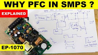
- In this video i explained repair Sony play station PS4 PSU Power Supply ADP-200ER - power factor correction circuit. i explained what is PFC and how it works. working principle of power factor correction. it is used to maintain dc voltage at a preset voltage level to maintain line regulation and load regulation. it increases the converter efficiency.
how to repair sony psu4 psu
sony ps4 functional description
how to repair sony ps4 without circuit diagram or service manual
PS4 power Supply Part-1 • #301 Sony PS4 Power Su...
Part 2 input protection, EMI/RFI filter circuit • #304 Sony PS4 Power Su...
Part 4 Standby circuit using DAP041 • #309 Sony PS4 Power Su...
playstation 4,sony ps4 power supply,sony ps4 power supply repair,sony ps4 power supply voltage,sony playstation 4,sony playstation 4 power,sony playstation 4 power supply,ps4 psu repair,ps4 pro psu repair,ps4 functional description,ps4 power supply repair cost,ps4 troubleshooting,circuit diagram,service manual,power supply repair,power factor correction,power factor explained,pfc power supply module,functional description,2PCS02,IE2PCS02,IE2PCS02G  Наука
Наука


This is perhaps the most detailed explanation pfc part of smps on youtube. This series is greatly helpful because the power supply being explained is from a ps4, an immensely famous device. I will have to revisit this series often because it has become a point of reference in my learning endevour. A big thank you to Haseeb who is continually pouring out precious gems in technical education.
best regards and special thanks for your valuable feedback. it is my pleasure that my work is helpful
I always enjoy watching your teachings. You are able to enlarge my layman understanding of SMPS electronics every time.
Love this series. Trying to apply the knowledge you have given to the adp-300cr power supply. Thank you
best regards and special thanks
جزاك الله خيرا اخي ، شرح ممتاز
fully watched awesome superb informative sharing big thumbs 70 thanks best regards for your adorable work
I love this PS4 videos, thank you
Saty Blessed & Wish You Good Luck My Dear Brother Big Thumbs Up # 36
This my second time I am watching your amazing vid, we really need to know the process of electronics cards and what is the purpose of every component on the board what is it's functionality, after that we can fix stuff, many many thanks for your big offers I really broad of your channel
👍 *_# 87 and hearty greetings to you and your channel, dear Haseeb Electronics! Thank you for this interesting upload, I am glad that I have watched it. Best wishes to you from your LW who remains one of your channel's loyal fans._* 🙋🎄 🎅
Thanks for visiting, please accept my best regards
happy new year
so much knowledge.. amazing.. thank you, master.. so glad I found your videos.. now I will be able to fix my customers SMPS hopefully on time.. :)
best regards
it is my pleasure
wishing you best of luck
Thanks for the demonstration 💝💝💝
Wonderful video dear friend, have a happy weekend!!!
Well explained tutorial 👌
Thanks for sharing good knowledge my brother thanks
Super, it is like music. Thanks
Приветик спасибо за обзор интересно было посмотреть.
Lk 5 Assalamualaikum bhai
Very well explained 👍😇
Nice video 👍👍👍👍
amazing analysis.
best regards and special thanks
This vid was really rear so much info, I like to investigate more complex SMP and I want to ask about schematic how can I get SMP schematic since I have an Emerson SMP with 24vdc and 40A, asking for your help brother Haseeb. Many thanks and this channel is the best one
Good morning 🙏 bhai
Great upload 👌 👍
I understood PFC Thank you sir 🙏🏻🙏🏻🙏🏻🙏🏻
It is my pleasure
Brilliant! Your my favorite Haseeb! 😊
Thank you so much 😀
Very nice
Salam M Haseeb, nice to see you back ! can you put a load on the output to see how good it regulates. I have an Xbox 16A but the voltage drop is high (2v for 5A bulb lamp) Thank and Salam Aleikum.
Thank you my Friend 👍🙏🏻
Thank you too
SOOO GOOD
Good like this information
Thanks and welcome
Makmal hony tk dakh raha , nice work dear friend
Salam brother. Great tutorial, thank you
A same psu came in the other day with that coil you mentioned in the PFC circuit fractured, The console seems turning on just fine but it gives that strong burning plastic smell.
Is there a possibility to replace that coil with another from pc PSUs ?
very good. thank you.
Welcome!
Our exceptional Haseeb 👍
best regards and special thanks
@@HaseebElectronics you deserve better sir👍
Nice sir👌👍
Thanks and welcome
Lk 89 wonderful ❤❤👍😊
Thank you so much
What components should I look up to if the 12v keeps dropping to almost 0 Volts after switching the Power Supply?
Great Video !
Hi Haseeb, really THANK YOU for your nice & clear explanations on The switching power supply!
I would like to read your general opinion on the PFC circuitry can be found nowadays inside switching power supplies, expecially the bigger ones.
In repairing, I find them, several times almost completely blown-out.
I've found this circuitry usually right in before the mains bridge and usually works with it's own controller circuitry & power switching device.
To quickly remove the SMPS fault, even while accepting some degradation of the appliance itself, would it be a good idea to functionally remove this circuitry?
Several times I find a lot complex PFC circuitry, that are so damaged thati it wouyld be almost impossible eve identify the components have been used!
For example, right now I'm repairing an Air conditioner SMPS, in which the PFC power IGBT completely blown out together it's controller, which marking is unfortunately completely unreadable .
In other occasions, I removed this circuit, and it seems to work, (of course not take into account EU normatives).
I would like to know, your opinion on this.
Ciao from Italy!
Mario Di Stefano
good afternoon, could you tell me the value of resistors r53 and r54? thank you in advance thank you
Hello brother thanks for your video, New subscriber. I want to connect a GPS tracker ( DC 9V - 95V ) to this power supply can yo please tell me where to use? Thanks for your informative teachings
What is the value of the big colorful resistor ?
Hi, haseeb, my ps4 ADP-200ER power supply capacitor is blown, i want to replace the capacitor, can you plz tell me which capacitor to put. please help me with capacitor reading. thank you.
Hi. Great video, very informative. I have the same ps4 psu, but the pfc is not staring when i engage the 5 v with the standby. the big cap stays at 322 v and , obviously, i don’t have the 12 v output. There is no voltage at pin 6 or 7 (where it should be 15 v) of the ic. What component provides the 15v to the ic.? What should I check next?
yes
it must maintain pfc voltage
there is a switching transistor in vcc pin track, check it
check enable signal from optocoupler
@@HaseebElectronics thanks for your reply. I'm new at this, so can you tell me where is this switching transistor located? I cannot trace the Vcc track . It should have the same V as the Vcc pin (like 15V)? Thank you in advance for your help
@@HaseebElectronics Hi . I found the VCC track and the mosfet. I have 18 v at the drain, and 23mv at the gate. there's no change when I give the power on comand. DNP012A could be faulty?
Hi iam working on a sharp TU-T2HR32DVR has no stand by light 12v is present at the input and there is 3.3v at I.C. Of number EM78P311N pin 28 VDD microprocessor. I have dis connect the HDD but still the fault still there I Dried to get the schematic diagram no success any ideas please !!!
thanks for sharing knowledge on power supply, but how to increase current not voltage of output???
no dear we cannot increase the current of any circuit. if we will try to increase the current, we will destroy it. it is the fact
@@HaseebElectronics it means weak power supply remains weak! What if I want to load more😆??
Fault finding methods pfc primary side 320v main cap ok but no vcc to pfc ic running vcc auxiliary winding
hello thank you for all his information, if I lose the 400v when I turn on the ps4 the problem can come from where please? (no 12v) the standby is ok
after standby power section
PSON command
then PFC starts
after that 12v power section starts
if any section fails, PFC and 12 volt power section will turn off
if PFC cannot take start, next 12v section fails to start
@@HaseebElectronics from what you say the problem would come from the secondary part of the power supply or it is not necessary? Thank you very much for your answer.
You said in the next video you will discuss high power section. But next video is final video that is standby section. My psu has standby 4.75v but on shorting 5v and acdc_stby, 12v is not getting on. 🥺
video number 355
ruclips.net/video/bgitC_E1q1A/видео.html
@@HaseebElectronics ok thankyou haseeb sab. I checked till 320 then i thought you didn't upload. You explain very well thankyou for sharing your knowledge with us 😀✌️
Good, you have the same of adp-240ar
@@HaseebElectronics i have adp-240ar who is burning mosfet 13nm60n, i couldn't find with the fault
@@HaseebElectronics ok, good , i Will going to send you , thanks for now 👍
Hi Mr Haseeb. If current sense resistor is out, would it cause the whole psu to not work?
exactly, because it becomes in series of the dc rail. so if it is OUT, next circuit will not get voltage to drive, so PSU will remain dead
@@HaseebElectronics thank you so much. Your video really explains A lot of the why's for me. I must know the why's in order to learn.
pfc smps when test with series lamp why we on off the lamp
because PFC circuit draws more current, and series lamp cannot provide required current and in result the voltage drop across the lamp, which causes to restarting the PFC controller
Hi...i have a tv use pfc power supply.when turn on tv in stanby.voltage at bridge fluctuation but at main capacitor stable.when power on the tv...ps on from mb will fluctuation.so the stanby green just blink2.what happen to pfc side.the output voltage stable.
Sir ❤❤❤❤❤ hide ma chiya tha
And it is a reactor....
12 volte missing, only standby 5 volte, how can doing?
please check 400 volt on capacitor by making PSON jumper, the PFC circuit must turn ON to boost the voltage at main dc capacitor to 400 -410 volt DC. then the push pull circuit will enable to provide 12 volt
You are repeating the same thing over and over and over and over and over and over, there are no information or real explanation , just repeating and observing the out come. do you thing you know how to explain ??????????????
oh
really sorry for that