
- Видео 42
- Просмотров 32 310
frankie mashockie
США
Добавлен 5 авг 2023
Hello! I made this channel to share what personal and work-related (I am Lab Instrumentation Engineer at a biotech company) projects I am working on. My videos mainly focus on electronics and my attempts at fixing them. I am completely self-taught in electrical engineering. So please feel free to correct me in the comments if I say anything incorrect.
This channel is meant to be a video blog on my experience as a hobbyist and professional working in electronics. These are not meant to be 'how-to' videos nor do I try to pass them off as such. Working on electronics at mains voltage can be dangerous and deadly. Please take precautions if you are looking to do the same.
This channel is meant to be a video blog on my experience as a hobbyist and professional working in electronics. These are not meant to be 'how-to' videos nor do I try to pass them off as such. Working on electronics at mains voltage can be dangerous and deadly. Please take precautions if you are looking to do the same.
ThermoFisher SimpliAmp Thermal Cycler Repair/Mod for Cal Failures
In this video I perform a repair/modification to a piece of equipment this is a workhorse in our lab: ThermoFisher's SimpliAmp thermal cycler or PCR machine. This one is failing temperature verification. Since there is no way to perform calibration adjustment on these, I created a mod that will bring the instrument back into tolerance. I also go over what a PCR machine is, how they work, and how to perform calibration verification on this model. Hope this is helpful to someone!
A quick note which I meant to cover in this video: If you do attempt this mod, I recommend removing the entire top panel of the instrument and the heated cover assembly. It is rather easy to do. The reason being is ...
A quick note which I meant to cover in this video: If you do attempt this mod, I recommend removing the entire top panel of the instrument and the heated cover assembly. It is rather easy to do. The reason being is ...
Просмотров: 60
Видео


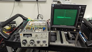
HP 8654A Signal Generator Repair - Range Knob
Просмотров 2214 часа назад
What's up everyone! Been busy with work and a few projects, but here's a shorter video on repairing my recently acquired HP 8654A signal generator. The range knob would only work for the 250-520MHz setting. Let's open it up and see what we find!

ThermoFisher XTR Centrifuge Main PCB Repair - E25 error
Просмотров 332Месяц назад
Another XTR Centrifuge main board repair in case you haven't gotten enough! This one was a bit perplexing at first. I took this board out of a centrifuge that required a decon. It sat in my shop for a bit and I used it as a reference briefly to repair another XTR PCB. And between now and then, it developed this E25 fault! Did I do something to damage it? Watch as I try to troubleshoot this myst...

ThermoFisher XTR Centrifuge Main board Repair - Latch Issues & E44/E45 Errors
Просмотров 208Месяц назад
What's up y'all! in this video I repair a ThermoFisher Sorvall Legend XTR Centrifuge main PCB. The end user stated that one of the latches was not working. After fixing the latches, I discovered the unit was also triggering E44 and E45 error codes. Also, it appeared that an unknown substance was spilled on the board. Fortunately this one ends in a successful repair! this is the first time I rep...

Beckman Coulter Optima XE-90 Ultracentrifuge Repair - Power Supply Failure (Again)
Просмотров 396Месяц назад
What's up everyone! In this video I perform a repair of a Beckman Coulter Optima XE-90 power supply that provides power to the unit's SCB and TEM. The supply has part # B05755 and is $7500 to replace (that's just for the part!) I did a 3 part video series on repairing this same supply about 6-7 months ago. And it has failed again! Same module but different cause. However, both issues seem relat...

Sony Playstation 5 Repair Part 1: The Power Supply
Просмотров 9302 месяца назад
What's up y'all! My partner asked if we could get a Sony PS5. She plays video games; I haven't been much of a gamer since I was 15 years old. So I offered a compromise: we can buy a non-working one so we can a) save some money (potentially) b) I get some entertainment out of it as well! 😂 So I bought one that I was certain would not power up at all with the mindset that it would likely be due t...
HP 8557A Spectrum Analyzer w/ 182T Repair - Part 2!
Просмотров 5672 месяца назад
Hey everyone! A lot has happened since I first released part 1 of this series (here: ruclips.net/video/WiRh1hfluQw/видео.html) attempting to repair this HP 8557A spectrum analyzer plugin in a 182T mainframe. Auroras, eclipses, you name it! It took me a while to return this project because things got busy with work and I struggled to find the right material to perform this part of the repair: re...

TRek Model 610E High Voltage Supply/Amplifier Teardown
Просмотров 5632 месяца назад
What's up everyone! Figured I'd try something a bit different - a teardown of this neat piece of equipment! It is a TRek 610E HV Supply/Amplifier/Controller. It can deliver up to 10,000VDC at up to 2mA!! At only 20W power it is definitely not the most powerful supply I've come across, but it can deliver the highest potential by far! This device was once part of a complex apparatus at my company...

Tektronix TM503 Power Supply Module Repair
Просмотров 3143 месяца назад
Hey y'all finally got back to some personal projects! This is a Tektronix TM503 power supply module. I got it off eBay and the seller stated it was not working. In this video I troubleshoot and fix the issue. But it was not the fault I was expecting... 0:00 - Intro/project updates 2:05 - description of fault 3:55 - visual inspection 6:01 - testing the voltage rails 9:41 - testing the 33.5V rail...
Invitrogen Countess II Cell Counter Repair - Booting Issues/SD Card Cloning
Просмотров 3343 месяца назад
Hey y'all! Another work related repair vid. In this video I show how you can repair an Invitrogen Countess II cell counter with booting issues by cloning the SD card. The SD card basically acts a hard drive for these units and contains the OS for the HMI. Hope someone finds this helpful! 0:00 - Intro/Teardown 4:45 - Overview of fault & troubleshooting process 10:18 - Cloning SD card with DiskGe...
ThermoFisher Sorvall Legend XTR Main Board Repair - Flashing the Infineon XC164CS MCU
Просмотров 3733 месяца назад
In this video I walk you through a ThermoFisher Sorvall Legend XTR centrifuge main board repair - specifically, the main board's microcontroller (MCU). The MCU is an Infineon SAF-XC164CS-16F. I will walk you through how to flash this chip. I will also discuss additional main board failures on this model centrifuge, as well as additional repairs not performed by the manufacturer. Hope this is he...
Consolidated Sterilizer Systems SSR-3A Autoclave Preventative Maintenance
Просмотров 2304 месяца назад
Another work related video! In this video I walk you through how I perform preventative maintenance on one of our autoclaves, specifically the Consolidated Sterilizer Systems SSR-3A model. But a lot of this is applicable to other autoclave models as well. Hope this is helpful to someone - thanks for watching! testing high-limit pressure switch ruclips.net/video/YacWgK456vQ/видео.html 0:00 Intro...
Molecular Devices SpectraMax ABS Plus - Repair/Optical Alignment
Просмотров 3374 месяца назад
Something a bit different than my past videos as this is a work related repair! As an in-house engineer for a biotech company, one of my biggest challenges is dealing with the repair prevention strategies lab equipment manufactures employ - refusing spare parts, service manuals, schematics, etc. Some are worse than others, but this company Molecular Devices is a top offender. The SpectraMax ABS...
HP 8557A Spectrum Analyzer in HP 182T display Repair Part 1 (182T power supply)
Просмотров 5854 месяца назад
In part 1 of this video series I attempt to tackle an intermittent and elusive fault on the 182T CRT display Part 2 here! ruclips.net/video/ignusqTYAeE/видео.html 0:00 - Intro/Overview 8:53 - Visual inspection/teardown 12:55 - 182T power rail testing 14:50 - scratchy intensity pot symptom 15:40 - 3kV test point check 16:25 - A2 control module PCB cleaning 17:16 - New fault symptom, loss of HV s...
Tektronix CG5011 Oscilloscope Calibrator - Part 4 (Fixed!)
Просмотров 4545 месяцев назад
The final conclusion to this series of repair videos on this Tektronix CG5011. The issue here was due to my own mistake... but I resolved it in the end! Also, there are numerous errors in the service manual's troubleshooting trees and checks which was really annoying. Just be mindful of that if you ever have to fix one of these yourself. 0:00 - Intro 1:25 - extender daughter cable 5:15 - Overvi...
Tektronix SG503 Quick Follow-Up: Power Rails & 10MHz setting
Просмотров 2185 месяцев назад
Tektronix SG503 Quick Follow-Up: Power Rails & 10MHz setting
Tektronix SG503 Leveled Sine Wave Generator Repair - Display Issues (Part 2, Fixed!!)
Просмотров 4415 месяцев назад
Tektronix SG503 Leveled Sine Wave Generator Repair - Display Issues (Part 2, Fixed!!)
Tektronix SG503 Leveled Sine Wave Generator Repair: Display & Power Issues (Part 1)
Просмотров 4125 месяцев назад
Tektronix SG503 Leveled Sine Wave Generator Repair: Display & Power Issues (Part 1)
Tektronix CG5011 Repair Part 3: DC Freq Mode
Просмотров 1936 месяцев назад
Tektronix CG5011 Repair Part 3: DC Freq Mode
Tektronix CG5011 Oscilloscope Calibrator Repair - Part 2
Просмотров 2916 месяцев назад
Tektronix CG5011 Oscilloscope Calibrator Repair - Part 2
Tektronix CG5011 Oscilloscope Calibrator (w TM5003 mainframe) Repair: Part 1
Просмотров 4816 месяцев назад
Tektronix CG5011 Oscilloscope Calibrator (w TM5003 mainframe) Repair: Part 1
Tektronix 2230 Scope Repair Part 5: Another Display Issue
Просмотров 3176 месяцев назад
Tektronix 2230 Scope Repair Part 5: Another Display Issue
HP 8116A 50 MHz Pulse Generator Repair: E53 error
Просмотров 5096 месяцев назад
HP 8116A 50 MHz Pulse Generator Repair: E53 error
Tektronix 2230 Oscilloscope Repair Part 4: Vertical Attenuators Fixed!
Просмотров 3647 месяцев назад
Tektronix 2230 Oscilloscope Repair Part 4: Vertical Attenuators Fixed!
HP 6038A Power Supply: Calibration with GPIB Controller
Просмотров 5337 месяцев назад
HP 6038A Power Supply: Calibration with GPIB Controller
Tektronix 2230 Oscilloscope Repair Part 3: Digital Circuitry/Readout Fixed!!
Просмотров 6297 месяцев назад
Tektronix 2230 Oscilloscope Repair Part 3: Digital Circuitry/Readout Fixed!!
Tektronix 2230 Oscilloscope Repair Part 2: Analog Circuit Partially Fixed!
Просмотров 9967 месяцев назад
Tektronix 2230 Oscilloscope Repair Part 2: Analog Circuit Partially Fixed!
Tektronix 2230 Oscilloscope Repair: Part 1
Просмотров 1,6 тыс.7 месяцев назад
Tektronix 2230 Oscilloscope Repair: Part 1
HP 6038A Power Supply Repair Continued: Further Voltage & Performance Testing
Просмотров 1,2 тыс.7 месяцев назад
HP 6038A Power Supply Repair Continued: Further Voltage & Performance Testing
Love it 😊
Great work ! one word of caution when dealing with high spec equipment is to think about dissimilar metals and contact surfaces before adding blobs of solder as this could bite you on the arse one day !.
thanks Andy! And good point 😁
Hi Frank well done some hams have found out moth balls (naptha) stops corrosion of contacts. 0db into 50 ohm load is .225v rms. if you don,t terminate at the scope end the 30pf per m coax will give a roll off. 0.225v rms should give that times 2.828 =0.6363 v
thanks! yea I still have a lot to learn about RF transmission and matching impedence. Appreciate your input and thank you for watching the vid!
I should mention that the TDS754 has 50ohm input which I had set. I was thinking this roll off was due moreso to the lack of bandwidth when measuring 250MHz on a 500MHz scope. Would I still need to terminate with 50ohm termination?
@@fmashockie Yes Frank it should be OK with a 50 ohm termination. Some scopes have this. You could check your generator attenuator against the hp attenuator you have.
First of all, I would like to thank you for the help you gave me with this video. I just can't get memtool 2021, can you please send it to me?
Glad you found it helpful! Link for downloading MemTool is in the description
so you have to take off that boot to undo a connection to get the pcb out?
Yep thats correct!
The current loop seems installed reversed.
If you're referring to the arrow on it, that could be. But by the end of the video, the circuit for the current loop was corrected.
Nice video. I have one of these XTR that's giving me the same Error E-25 and I'd like to try and replace the shunts. Do you have a source for purchasing the shunts or the specs for the shuts? Thank you.
Do you offer service on these? Can I ship you only the board for replacing the shuts? I'm in San Diego so shipping the whole centrifuge is not ideal. Thanks.
@@anytimelabtrader Yes! I just started taking on independent work. For lab equipment PCBs and power supplies. I can offer competitive pricing, quick turnaround times, and a warranty on repair. If it is equipment I already have here (like the XTR for example) no need to ship the entire unit. Other equipment that I don't have available, but you'd like a board sent would have to be evaluated on case by case basis as to whether the board or the entire unit is required to be shipped. Feel free to reach out via my email at fmashockie@gmail.com. But if you do wish to try to replace the shunts yourself, here's the link to the ones I use www.digikey.com/en/products/detail/sumida-america-inc/CPFC74NP-PS02H2A20/1879019
Nice !.....cheers.
Thanks Andy!
Hi Frankie, That is a pretty typical repair for an event where liquid damage happened to a board. It does damage in more than one place and one has to systematically fix the defects one by one. The wire repair for the relay coil pin that had lost the top pad was how would I have done it, that will work and be reliable. Also, you got a lot of great experience from fixing this board. Thanks for sharing, I enjoyed it, very interesting stuff. Kind regards, Duncan
Thanks Duncan! Really appreciate your input and feedback!
For a second I thought it was the same machine as that power supply hehehehe Quick one, what are those big blue rounded things? Hall effect sensors?
Yea that power supply was for a bigger beast! Ultracentrifuge that goes up to 90k rpm! This guy only does I think a max of 15000rpm (depending on rotor type). And yes the blue things are current transducers using hall effect technology! LTSR15-NP. I know one is involved in the protection circuit.
You definitely have a unique channel. NICE!
thanks for the feedback Joel! 🙏🙏
Amazing work, the repair is totally worth it since the boards are about 3k new. Highly confident to use your service.
Thank you!!!
Hi Frankie I have just got 2 of these plugins but minus the big knobs on the left hand side, I will have to make some out of aluminum on the lathe. Would appreciate a blown up picture of these as they are so complex.
Hey glad to help you out but which part are you referring to exactly?
Hi Frankie,it,s the attenuation/ref level/variable and the bandwidth /resolution they seem to have concentric shafts all very complex. Also yours has a mechanical freq readout mine have electronic display (dont think its a counter just a DVM display). Thanks
@@mechmania8450 gotcha. Is yours a 8557A? I know some of the 8557s had digital readouts. So you need knobs for the Optimum Level, Coarse Reference Level, and Fine Reference Level. As well as knobs for the Frequency Span/Div + Bandwidth Res? Thats 5 separate knobs. Am I understanding you correctly? If not why don't you shoot me an email (will need a way to send you photos anyway). My email is in the bio of my channel
You might get some additional help by looking at the service manual. It has an exploded diagram of the front-end. Because yes both those switches are concentric. But one is tri-stacked (amplitude) and the other double-stacked. You correct it is a pretty complex set of switches.
@@fmashockie Hi Frankie Cannot find you email. I have a scale for the attenuation/ref level and I am making a knob in aluminum. However I am not share how the bandwith/sweep width works there is a hole on the panel. Had me confused for a bit with the atten knob which has a channel front to back however this is not needed but it must weaken the knob. But I still wonder how the bw/sweep works. I have repaired helipots in the past ,bad connection at end of wire wound track.. Use some agressive soldering flux.
Oh ! get the boss to buy you a thermal camera ! Are those transistors mounted on a heat sink ?....Nice vid !.....cheers.
yes! been meaning to get one of those for a while!!!
@@fmashockie :)
This was an interesting Video. I think it also verifies rule 0: Do a very detailed visual inspection. Followed by rule 1: Check your voltages 😂. Maybe somebody has a suggestion for rule 2?
For switching power supplies, rule 2 might be check your frequencies (only makes sense if you have a known good unit). Aside from microscope inspection that someone else mentions, a thermal camera would often be helpful.
Question for the viewers out there who might have more experience: am I wrong to say the manufacturer of this centrifuge should have picked a supply with greater output? The thermoelectric module (TEM) that cools this beast can draw 8A 60V at max setting. The supply is only rated for a max of 8A. I think they should have went with a higher rating but curious to hear your thoughts!
I'd say it depends on how it's rated. If the manufacturer simply says 8 A max, I'd expect it to actually live up to that for its rated lifetime, as long as it stays in the temperature range (and whatever other parameters). If they derate it under certain conditions, it should still be able to do 8 A for lifetime, provided you avoid the derating conditions.
@@markp5726 thank you! I was just curious because I've worked on a lot of lab equipment power supplies, and I've yet to see one that was not overrated a little bit. So I thought this was odd.
hi, does anyone can send me an image of working COUNTESS II sd ? thank you in advance, k.
Nice job young man👍
Thank you Joel!! Always appreciate your feedback!
Mechanical stress on caps due to differing expansion coefficients of ceramic and copper with pc board substrate is a known cause of smd failures. Was not surprised to see that it was the cause of the fets smoking and burning up. That high frequency would have run the transformer hot, luckily it did not get hot enough for permanent damage it seems. It was an interesting video, fault finding is fascinating stuff. Best regards, Duncan South Africa
Took me a while to make that connection but glad you still enjoyed the video! This is my favorite part of my job but I don't get to do it as much as I'd like. We'd be in bad shape if I was working on PCBs like this everyday!
@@fmashockie I use a cheap usb microscope with 800 times magnification to examine boards, and take screenshots of what I find. Not a week goes by that I do not use the microscope to look for stuff or take images to put into reports. Or look at the numbers on components.
@@Uncle-Duncan-Shack I might need to make an investment in a microscope that powerful. I think mine is only 10x
Glad you found it! That's some serious bad design there... falling off? Holy fuck! For a bit I thought you had counterfeit FETs there (Even from the big 3 it happens, ask how I know...) Great video, a tiny bit scary ;)
Thanks Charles! It's crazy right!? A SMPS that costs $7500 shouldn't be having this many failures so early in its lifespan!
Around a decade ago, I watched someone open up an audio amp. I don't recall whether they planned to fix it or wanted parts out of it, but we were all amazed when they saw that surface mount resistors had fallen off or tombstoned. I think they surrounded a microcontroller or something else that shouldn't get hot, so it was quite strange. The board also wasn't discolored IIRC. If the unit was produced when RoHS was new, I wonder if the wrong solder was used, with a melting point that was too low.
Update: At @31:40 I mention R9 having gone open after I intially tested it (although I'm still not sure if I made a mistake). However, I heard somewhere that this is actually a fuseable resistor. Without a schematic, these can be hard to identify as they can look just like normal resistors. But it explains how it could have easily tested normally at one point, and then later on gone open. Not to say that couldn't have happened with a normal resistor - if you apply enough power to it 😆But still if you plan to do this repair, and you come across R9 open, probably best to replace with a fusable one!
Enjoyed following along but don't know if its a cultural thing but I have never heard 'hysteresis' pronounced that way! in the uk its 'hiss tor ee sis' When I change two blown power devices the first thing I do after power up, if nothing changes, is to check to see if they are still ok because what killed them once can kill them again. Whacky I can't hear anything ! Last thing please be a bit more aggressive with the scope you can get the waveforms so we know what they are as opposed to being off screen or we are looking at the low frequency crap etc ! nice one and the motherboard next !....cheers.
Thanks as always Andy! I really do appreciate your feedback both good and bad. I'll be honest - I wasn't sure if I was pronoucing hysteresis right 😂 I can definitely do a better job with the scope for you guys - make sure I give you a clear shot moving forward and ensure it is triggered properly. And I know the sounds from the inductor didn't sound too bad on video, but man this thing was chirping away in-person - especially at 250W! Thanks as always for taking the time to watch and comment! 🙏🙏
@@fmashockie :) probably my age (nearly 60) as to why I can't hear it LOL !! yeah a few little tips there...always interesting to watch !
UPDATE: The @Thesignalpath released a video on HV Amplifier design yesterday (link here: ruclips.net/video/1voyXXpq-k0/видео.html). This video is fantastic and answers a lot of the questions/uncertainties I had about the 610E circuitry. 1) He defines what that long cylindrical tube is at the 12:45 mark. It is not a current monitoring device but safely provides feedback to the low voltage amplifier board via a custom resistive divider. 2) If you look at 6:37 mark, I completely gloss over this because I didn't know what they were, but you can see this plexiglass circle right beneath one of the HV tubes at the top right corner. That is actually a light pipe for an optocoupler! This optocoupler is what allows the output signal of the low voltage amplifier to reach the HV portion of the circuitry since there is no way to safely physically connect both parts of those circuits. Very cool! Highly recommend you check out that Signal Path video if my video left you with unanswered questions!
feynman: the pleasure of finding things out
that is one of the main reasons I do this!
nice job--well explained
Thanks for watching Stan and I appreciate your feedback!
Common approach to repair SMPS generally speaking in my mind; Mosfets, resistors, capacitors, Diodes, controller's. I am sure others will diag them differently. Mostly used is a multimeter.
Good point! I suppose I should have clarified depending on the symptom. But if I have no voltage on the secondary side as in this case, I like to check the controller first because the datasheets for them provide so much information and you can get a lot diagnostics from checking with a scope. And I'm not saying because I think the controller is the issue, but knowing it's operation mode (under voltage lockout, over voltage lockout, hysteresis, etc.) can lead you to finding faults with associated components
@@fmashockie Just remember, time is money. Otherwise I agree.
@@joelkist6493 ain't that the truth! You're right I probably could have figured this out faster going with your approach. But there have been so many videos done on repairing this power supply that I thought it would be cool to show how it actually worked.
@@fmashockie If the main switching fets are blown then its likely you also have a shorted output pin on the controller IC that drives the gate of said fet. For combination chips that control both pfc & smps you can still have the pfc portion working despite the smps portion blown, which you did.
@@spikester thanks for that input! Interestingly, the DAP053T was still sending gate signals to both HS and LS MOSFETs despite them blowing. I show that in the vid @30:46. I'm not 100% sure what went wrong with the DAP053T, but it seems to be a common failure in this supply from what I've seen
And off with the lid….whooo…to big fat 6BK4’s..don’t see things like that much these days…25Kv, 1mA “Hot Source” MOSFET! Ah, yeah-nah, they are thermionic valves…I have a Marconi Mk-IV monochrome TV monitor here that has one in it as a shunt reg. If you have the ability to draw the circuit from the gear, this is an excellent piece of gear to learn from, I’d be “into this like a bull dog into s custard pie” as there is no circuit online…just love to know how those 6BK4’s are used and where the rectifiers are. Reckon that copper foil covered block is a Cockroft-Walton multiplier, but the other copper shielded cylinder in the front left hand corner…reckon it is some really fancy high isolation optocoipler or transformer…..geez I want to extract the circuit of this thing!
Thought you would enjoy this one Globe Collector! I was fascinated by this one when I opened it up as I don't have much experience with equipment like this. I can definitely spend some time outlining the circuit. Interestingly, the Signal Path just released an in depth video on HV Amplification. I'm going to give that a watch. I was very curious as to what that long shielded cylinder was. I did open it up and it had some passive components inside, but there was one super long axial component that runs almost the length of the tube inside. I couldn't tell what it was. I thought perhaps it was some kind of current monitoring device. The manual for this thing was a bit of a letdown - no schematics. So I can definitely spend some time mapping it out!
So I watched the Signal Path's video on HV amplification design I was telling you about. It is a perfect supplement to this video. He goes into much greater detail than I ever could on how these work and even does a teardown on another Trek unit - 20kV one! He defines the long cylinder. And you're pretty much right - it is resistive divider that allows for feedback from the HV to the low voltage circuitry. Also defines some other components I missed, like the light pipe optocouplers below the HV tubes that are used to send the output signal from the amplifier to the HV side. So cool! Definitely check it out!
Geez Frankie, I have to give it to you for paitence and tenacity, qualities very few possess these days. I looked up that jFET, it is something like 2N4391, 2N4392 or 2N4393….although not specifically listed in the HP part translation lists, 1855-0414 is a 2N4393 and the next listed is 1855-0420, which is a 2N4391…then those in berween are most likley to be SELECTED versions….i.e. somone at HP has sat down in a little room with a curve tracer and gone through a whole heap of 2N439x FETs and simply selected ones that wotk the sbsolute best in this circuit. If you look in the circuit, you can see it is switching the signal level at the output of the amplifier composed of Q17A/B, Q11, Q12, Q13, Q18 and transistors inside U1 (D and E). the output comes out via a 4K64, (R11), and then either has 511 Ohms (R20) to ground if Q19 is on or no R20 if Q19 is off. What they would have selected for is rds-on, because it adds in series with R20. If you can find a FET with a lower rds-on, then you can simply trim-up by adding resistors in series with R20 or just increasing the value of R20….its just to get the signal level spot-on a certain value when Q19 is turned on. I have tons of 2N4093’s here if you want any of those, the main difference being that the 2N4393 can handle 50mA forward bias gate current, whereas the 2N4093 is only about 10mA. The main difference between the 391, 392 and 393 is what I thought, rds-on, of 30, 40 and 50 ohms respectively, same for the 091, 092 and 093. That 4% beryllium 96% copper is amazing stuff, but, yes it fatigues quite easily…i.e. breaks when bent back and fourth. The other property the nickel did not have was lack of elastic limit….my father is a mechanical engineer and talks about this stuff all the time…so you can bend a material…and if it has a high elastic limit and you don’t bend it to that limit, it will spring back to its original shape….this is why they put the 4% Be in the copper, to increase its elastic limit…just thought you’d like to know the term for it! Can’t believe your rotten lick with damaged front pannel controls…my Tek 7L5 had a badly smashed up beryllium copper fingered PCB based span per division switch…but I managed to cobble it sll back together. Watched you go through the spectrometer and was impressed by how you used zero blaze to zero it and calibrate it. Thes big companies that make such stuff…waaayyy underestimate the ingenuity of some individuals such as youreslf. Watched the autoclaves too, so say hello to BrAD and Clare for me…..scrape some scale out of their boilers for this bloke in Tassie!
The Globe Collector Returns! I hope you are doing well and that everything is good on your side of the globe! I was starting to miss your detailed analysis of my videos. I always learn so much from them. Thanks for that info regarding Q19 on the Vertical Driver board! Per the service manual, Q19 1855-0417 is on when Linear or 10dB/div is selected, and off when dB/div is selected. I was able to find the electrical characteristics on CuriousMarc’s website! Link here (drive.google.com/drive/folders/1e4pSjjSeVk8JM6O1EnnuL9jYS6FAK8hN). And you’re right: the on resistance for 1855-0417 is low at only 10ohms. It seems like 2N4391 would be a good alternative. Right now I have a J113 in it’s place and the unit still seems to work, but its Ron is 100ohms. I think I might do a J111 instead (I believe I have some of those). I also appreciate your offer for sending over some JFETs! Finding the correct material for those contacts was the most difficult part of this repair! And thank you for providing the correct material characteristic terms. Elastic limit is definitely better than ‘springy’ lol. Still curious to know what the originals are made of though because they seem a lot more durable than the CuBe fingerstock I used. Any thoughts on that? When I was looking at SAs to buy, I saw a 7L5 plug-in for sale in non-working condition. I almost bought it, but I would have had to grab a 7000 series mainframe as well. Maybe someday! Thanks for watching the spectrophotometer and autoclave vids as well! It felt good to solve that spectrophotometer issue. I enjoy sticking it to these manufacturers lol. And I’ll be sure to get those boilers properly flushed!
Oh, yes…the 7L5…I slmost forgot. I have two of them, one a froend bought to the door one evening snd I got right into it. It is s fiendishly complex circuit. Each individual circuit block is dort of easy enough to grasp, butbthevway thay all “talk to each other” is sheer digito-analog wizardry! I ended up buyong a second non-functional unit off fleabay just so I could swap functionsl blocks aroind between the two. I think the problem is in one or both of two sample and hold circuits that hold the centre freqiency horizontal position voltage. They use fancy Analog Devices opnamps with a swanky, low leakage capacitor in the feedback loop…this is supposed to hold about 99% of its charge for at least ten seconds according to the manual. In the unit my friend bought around…after fixing smashed multi position switches, bent pot shafts, shorted Tantalum caps, open circuit rail dropper resistors..I found that the outpus of both S and H’s were slammed to the negative rail. The charge is added to or removed from the capacitors via two ultra low leakage diodes inna TO-72 can on the input of the S and H circuits…these diodes sre still svailable and thay sre the ONLY diodes with this low leakage as far as I can tell…a dizzyingly tiny 1pA! About three orders of magnitude less than most other diodes! Currently I am procrastinating getting back onto them, the second fleabay unit is just sitting in there on top of the other one basically untouched. Still a bit pooped after the container move snd its the bloody middle of winter here in Tas, day temps around 50 pf your antiquated Farenheight and night temps around 40…. It is cycling between grey, drizzly and sopping wet to sunny and windy every frw days. Sunrise is 8.45 in the morning snd sunset is 4.30 in the afternoon. The day is gone before it starts! Glad the winter solstice has passed and the sun is slowly starting its southward move again. Mut be noce there in Philly though at the summer solstice. Go for a walk to the Stocks Bakery and get some of that cake and eat it on video…lot easier than fixing electronic gear! I went an bought some “Madeira Cake” at Coles…it weighed 450g, and since an imperial pound is 454g, I see why it is called “pound cake” and I suspect this is the nearest equivalent I can get here. Gave one to my father all covered in whipped cream as an 88th birthday cake, he ate about 65% of it in 15 minutes! Get back to you when I take the 7L5 “bull by the horns” again!
@@thanhhuynh272 I'll get to that bakery for you eventually! I think that will make for an interesting video... "what's he doing eating cake? I thought this was about repairing electronics" 😂😂
Great video Frankie. Enjoyed the trouble shooting process. Keep up the good work.
Thanks Joel! This one really tested my patience but I think the worst is behind me 😂😂 Always appreciate your feedback!
You have access to some amazing kit !! sooooo jealous ! Played with a lot of HV kit back in the day and always fascinating to see inside another high voltage supply.....cheers.
Thanks Andy! I'm glad I wasn't the only one who thought this one was pretty cool inside. I'm starting to run out of space! This one I didn't even know I had 😂
@@fmashockie :)
i want two
pretty neat right?! I love the HV shunt regulator tubes
Very cool device! Looks like you’re building a nice collection of test equipment.
Thanks Glen! Yep I'm starting to run out of space!
Where is those inoperable test equipment you're fixing?
If you mean videos? They are in the works! I finally got the parts I need to finish the HP 8557A SA so hopefully that will be the next one. And then everything else on that cart is waiting for that to be finished so those videos will be next!
deoxit makes deoxit gold for just that purpose
Thanks for that tip!! I wasn't aware of that product
Interesting tutorial...
Thanks Joel! I know it's not the most entertaining info but I like to try to help others repair this equipment without the manufacturer
@@fmashockie it is possible to have an SD image of Countess II. I do have an Countess II but does not boot at all, seems that SD is the problem. Can you help me ?
@@WirelessLanGrThessThesswireles shoot me an email. My email is in the description.
Hello Frankie…did watch this one. Really proud to see the sort of innovation and ingenuity many indoviduals of my generation are known for..but in your generation where these abilities are somewhat more sparse. Believe me, there are a lot of my generation out here who just would love to pass on our skills and understanding to a young-un before we a laid in a box for the last time. Tell yoi a thing about here in Australia…night or might mot apply to the United States…if I build a voltage controlled oscillator at home in my own bench or in my garage…”officialdom” won’t let it count on a resume or CV…but biuld the exact same VCO on a bench at a “designated workplace” like the beureau of meterology…then you can put that onto s CV! This is the sort of arrogance you are up against here from “MD” …they put the optical “magic” in the box there and how could a mere pleb like you ever comprehend it…my answer to that, if men can design 0:08 and build it, other men can reserach and understand it, so, yes don’t evr let them put ideas of inferiority into your head. I have moved my container full of electronics, but now a friend has to move tons of his gear, helped him strip down a Perkin Elmer Optima 3000 I.C.P. Spectrometer…this had tons of really advanced optics inside that make this one here look like child’s play…therevwas this grating in there that had two sets of rulings perpendicular to each other, one set for visible to one sensor and the other for UV to another sensor…also had a quartz prisim to get rid of the unwanted blazings from the grating. The optics bench had a resolution of 0.07nm! Will mack more comments in the near future when I get time to watch the videos. Love to see the varied diet of gear…love techs who will have a go at anything, unlike some who just stick to TV sets or the like….that’s loke eating Weet-Bix for breakfast, dinner and tea all year long…boring! Cheers!
Cool ! Did you give it a flick to try and get it going off camera ? lol! bet ya did, I would have! just to see if it needed encouragement Lol .....cheers nice job !
😂😂 there are a few things I handle off camera. Including the cursing in frustration 😂 thanks as always for watching Andy!
@@fmashockie :)
Awesome tutorial, somebody somewhere is going to be putting you on their Christmas card list ! Useful to know about that disk software...cheers.
Thanks Andy! I know these types of vids probably aren't the most entertaining but I'm confident someone, somewhere will find this helpful. This kind of issue would usually condemn one of these instruments because most people aren't paying the ridiculous cost to repair it from the manufacturer!
@@fmashockie Could not agree more :)
Wow, interesting fault !
Right!?? Glad I wasn't the only one who thought so! 😁
Thought it was going to be the 2k potential divider resistors !. They go high in the ones I had . Best put in a couple of 1 watt metal film resistors. well done Fankie !
Thanks Nick! Yea I wasn't expecting to see the bridge rectifier failed like that! So cool!
Always enjoy your vids mate!
thank you!! I appreciate it!
nice work from a fellow instrumentation technician
thank you! what field do you work in?
Did you by chance change the CMOS battery and is it shown, or possible to show location? I have a Beckman XE-100 but figure may be similar. They tell me they need to send someone out to do this for at least $3000! 7 yrs ago a few guys on LabWrench did it but they're not around. Thanks!
Yea so this is actually part 3 of a series of videos I did on repairing this unit's main power supply. If you go to part 1 (linked below) and scroll to ~4:30 mark, you'll see one of the I/O boards. Behind that board is the embedded CPU for the centrifuge. That is where CMOS battery is. It would be very easy to replace yourself. You just need to take the front panel off, remove the screws that the I/O PCB is mounted with and you can flip it around to access the CPU and replace the CMOS. FYI this is for an Optima XE series ultracentrifuge. It might be a different layout for a different model/series ultracentrifuge. That doesn't surprise me that they are charging you $3k for such a simple repair. ruclips.net/video/aNrVG8v53qw/видео.html
Thermo scientific bought my company out and made 40 of us redundant in 1 day so I automatically hate their equipment !! but good work on your part and interesting video.....cheers!!
I'm so sorry to hear that Andy. I've seen these large lab equipment companies like Thermo do that. They will literally buy small companies just to get the rights to a piece of equipment they've manufactured and then they will slap their name on it. It sucks because I bet the original companies probably provided much better support. Well if it is any consolation, I hope this video eats into their equipment servicing revenue 😂😂
@@fmashockie LOL! I appreciate your efforts :) !!
Interesting notations of your work.
thank you Joel!
ave enjoyer
great repair, fun to watch
well you earned a sub
thank you!
Quick correction: @5:40 I made a mistake about how the water level probes work. These units can actually work with only 1 water level probe. The high level probe (shorter) will cut water to the boiler when water level is sensed at the tip. When the water level drops below the probe, the unit calls for more water until the probe senses the water level again. The low level probe (longer) is actually the low-water cut-off probe (LWCO). So if the water in the boiler dips below this probe, the heating elements are de-energized to protect them (you CANNOT allow the heating elements to run dry!). Also, when you start up the boiler and it is empty, once the water level passes the LWCO probe, the contactor energizes (it can be heard closing at @42:21). Sorry for the mistake - I try to review these before I post and make corrections, but this one slipped by!
Is there a way to test the LWCO? I’m doing checks on a sterilizer and I’ve only been able to test the reliefs
@@shanepeterson8078 I'm sure there are a number of ways to test the LWCO and they come in a variety of different kinds. But what you can do is, first do this test when the boiler pressure is low, but the water level is at normal level. You can even disconnect the HV from the heating elements. But what you are looking for is 120V on the contactor coil. That should be there when the water level is normal, and the normal operating pressure switch is closed (and it should be if your unit is in the state I mentioned earlier). Now, you can disconnect the low level probe from the LWCO. If it is working properly, it should cut power to the contactor. That is the whole point of the LWCO - to prevent the heating elements from being energized when the water level gets too low. And that is the only reason for the low level probe. I might have mispoke in this video at some point, but the boiler can operate with only one of these probes. The low level one is strictly for LWCO. Hope this helps!
I hope you're familiar with BioRad's PCR song: ruclips.net/video/FpxwJNNufko/видео.html