I don't understand "sinking" whatsoever. After reading a bit it's power on. The secondary circuit (opened by something going ON) takes power from the first and it's sometimes 2 power driven circuits in other situations with other transistors. It's a bit complicated because people make loops and whatnot in examples. I'm not sure how many know what is happening.
informative video! it did clear a few things out for me. but could make or have a video that shows how a pnp and npn transistor in a circuit can be used as a latch? thanks!
I'm not into electronics, and I'm sure I'm wrong , but, why the load is not better connected on the emitter side? It is more intuitive to control a load providing it with power than to sinking one of his connectors. Is it disadvantageous or is it not possible?
thanks you, i understand it better now the way you explain it, looking forward for more videos like this, maybe a simple demonstration how to test an IC for shortage or bad using multi-meter
Simplified: "an NPN transistor is a 'normally open' relay. Energize the 'coil', or "base" and it closes allowing current to flow from contacts 'C' to 'E'." Not?
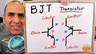
Complete NOOB here. Cool video BUT what we are always shown, regarding NPN transistors, is a little arrow pointing away from the emitter. And the direction of the arrow of the collector is never shown [tho we know it, to be pointing AWAY from the collector - NPN = Never Pointing iN] it is even illustrated on some NPN transistors. So, my question is: HOW does current travel in the opposite direction of the "imaginary" arrow of the collector, when the current at the base, permits it? It's my understanding that current can only travel one way, in a diode, an NOT the other. So, unless the diode in the collector branch, is some kind of zener diode, I don't understand. Please clarify - I want to learn. Cheers!
Imagine it this way. The arrow designates the direction of emitter current, using conventional current flow. Also the arrow is always on the emitter-base, or base-emitter side. You wont see a schematic with an arrow on the collector. The idea is that applying a base current across the arrows leads, you will completely break down the reverse biased collector junction (almost).


I don't understand "sinking" whatsoever. After reading a bit it's power on. The secondary circuit (opened by something going ON) takes power from the first and it's sometimes 2 power driven circuits in other situations with other transistors. It's a bit complicated because people make loops and whatnot in examples. I'm not sure how many know what is happening.
Thinking about PNP as Sourcing and NPN as Sinking makes a lot of sense. Thank you for the excellent video!
could u define sink i don it get
17368 Talia Radial
012 Yost Corner
7582 Lindgren Estate
Would I be able to hire you to teach this to me and my company? Would love to connect thank you.
Tenkyu veri gut mayfirend.
5125 Elva Rapids
292 Kovacek Dam
Thanks
informative video! it did clear a few things out for me. but could make or have a video that shows how a pnp and npn transistor in a circuit can be used as a latch? thanks!
4550 Lempi Circle
I'm not into electronics, and I'm sure I'm wrong , but, why the load is not better connected on the emitter side? It is more intuitive to control a load providing it with power than to sinking one of his connectors. Is it disadvantageous or is it not possible?
Do you mean 'sinking' or 'syncing'?
Sink
is there a way triggering the transistor by only passing current through ??
Nice video, keep it up, thanks for sharing it:)
thanks you, i understand it better now the way you explain it, looking forward for more videos like this, maybe a simple demonstration how to test an IC for shortage or bad using multi-meter
I like the term FLOATING. It explains so clear in my projects. Thank you!!
Easy to understand!! Very good explanation!! Thanks for your time and effort!!
Simplified: "an NPN transistor is a 'normally open' relay. Energize the 'coil', or "base" and it closes allowing current to flow from contacts 'C' to 'E'." Not?
So does a PNP act as a normally closed?
Very helpful, thanks!
Hi, really good explanation. Thank you very much! Is there a Transistor that is normally closed so when I Supply current to its base it opens?
Yes.. view my pnp video. ruclips.net/video/zQTAaGye2ng/видео.html
Complete NOOB here. Cool video BUT what we are always shown, regarding NPN transistors, is a little arrow pointing away from the emitter. And the direction of the arrow of the collector is never shown [tho we know it, to be pointing AWAY from the collector - NPN = Never Pointing iN] it is even illustrated on some NPN transistors. So, my question is: HOW does current travel in the opposite direction of the "imaginary" arrow of the collector, when the current at the base, permits it? It's my understanding that current can only travel one way, in a diode, an NOT the other. So, unless the diode in the collector branch, is some kind of zener diode, I don't understand. Please clarify - I want to learn. Cheers!
Imagine it this way. The arrow designates the direction of emitter current, using conventional current flow. Also the arrow is always on the emitter-base, or base-emitter side. You wont see a schematic with an arrow on the collector. The idea is that applying a base current across the arrows leads, you will completely break down the reverse biased collector junction (almost).
13002 is NPN or PNP?
Thank you so much!!!!
Thanks nice tutorial