Controlling a ONE MOTOR CVT Robot Arm

HTML-код
- Опубликовано: 1 окт 2024
- AD: Apply for AI Camp's summer scholarship for an incredible opportunity to build amazing artificial intelligence products this summer (it only takes 10 minutes): ai-camp.org/pa...
This is part 3 of the one-motor robot arm, which uses three continuously variable transmission clutches to translate the motor drive to three axes.
This isn’t a totally practical way to make a robot arm, but I wanted to see if it could be controlled electronically and if we can run inverse-kinematics on it.
Mostly it’s an experimental project, although it’s a little bit like a Hydraulic system which normally has one engine driving a hydraulic pump, and then multiple valves which switch the fluid to multiple hydraulic cylinders.
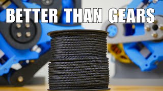
In my case though, my valves are actually continuously-variable transmissions which use ball-shaped clutches. As the ball tilts a larger or smaller part of the circumference runs between two wheels, giving either a reduction or enlargement in velocity.
There’s also a dead-spot in the middle so we can stop a specific axis with no friction. I’ve used worm gears to lock the axes in place while the clutch is at its dead-spot so they doesn’t free-wheel.
I’d previously made a two-wheeled differential drive robot using this system which worked well, but I’ve now expanded to three axes. The first one drives the whole robot around on its base which is made from a lazy Susan bearing - the clutch drives a spur gear around the inside of a large ring gear.
Axes two and three drive the shoulder and elbow of the robot. Two drive shafts exit the gearbox at the top, equally spaced from the centre of the robot. I then used a series of bevel gears to make a differential drive system that translates the motion to the shoulder and elbow axis.
CAD and Code: github.com/XRo...
You can support me on Patreon or buy my Merchandise:
***************************
Patreon: / xrobots
Merchandise: teespring.com/...
***************************
Affiliate links - I will get some money of you use them to sign up or buy something:
***************************
Matterhackers 3D printing supplies: www.matterhacke...?aff=7500
Music for your RUclips videos: share.epidemics...
***************************
Other socials:
***************************
Instagram: / xrobotsuk
Facebook: / xrobotsuk
Twitter: / xrobotsuk
***************************
CAD and Code for my projects: github.com/XRo...
Huge thanks to my Patrons, without whom my standard of living would drastically decline. Like, inside out-Farm Foods bag decline. Plus a very special shoutout to Lulzbot, Inc who keep me in LulzBot 3D printers and support me via Patreon.
HARDWARE/SOFTWARE
Below you can also find a lot of the typical tools, equipment and supplies used in my projects:
Filament from: www.3dfuel.com/
Lulzbot 3D Printers: bit.ly/2Sj6nil
Bearings from: simplybearings...
Lincoln Electric Welder: bit.ly/2Rqhqos
CNC Router: bit.ly/2QdsNjt
Ryobi Tools: bit.ly/2RhArcD
Axminster Micro Lathe: bit.ly/2Sj6eeN
3D Printer Filament: bit.ly/2PdcdUu
Soldering Iron: bit.ly/2DrNWDR
Vectric CNC Software: bit.ly/2zxpZqv
Why not join my community, who are mostly made up of actual geniuses. There’s a Facebook group and everything: / 287089964833488
XROBOTS
Former toy designer, current RUclips maker and general robotics, electrical and mechanical engineer, I’m a fan of doing it yourself and innovation by trial and error. My channel is where I share some of my useful and not-so-useful inventions, designs and maker advice. Iron Man is my go-to cosplay, and 3D printing can solve most issues - broken bolts, missing parts, world hunger, you name it.
XRobots is the community around my content where you can get in touch, share tips and advice, and more build FAQs, schematics and designs are also available.  Наука
Наука


this entire project is so awesome, the fact that this is all made with the limitations of 3d printers really shows how crazy the tech is. Imagine how simplified a metal-machined version of this could be! Serious innovation
The level of dedication to design and print each individual part of this build… over several iterations!
Also shows how brilliant James is
This is an amazing project, one thing that I noticed is that you could have used spiral bevel gears to reduce the backlash, by using the helical gears you would achieve a constant contact between the gears, although there is the problem that the friction would increase, it is not something that I imagine would be harder to 3D print.
Backlash, backlash, backlash... This isn't the first, nor will it be the last, while backlash is continuously kicking his ass. Personally, I don't think he wants to do the finish work on the parts.This is prototyping, but part of that of that is refinement. Clean the edges (deburr), and lubricate, Spiral bevel and herring bone FTW!
2:00 Thinking quickly, James constructs a home made speed controller using only some string, a squirrel, and a speed controller.
This is ridiculously satisfying to see how it all works. Insanely underrated
Awesome project! Not to be an annoying armchair engineer but try putting a 10k ohm pulldown resistor between the analog pin of the potentiometer and ground if you are using an Arduino to read the potentiometer data. This should hopefully clear most of the electrical noise because some cheaper Arduinos don't include them in their circuitry. I ran into the same problem a while back.
Thanks!
Any noise reduction achieved from this would likely come from the reduced output impedance, but it would have the downside of changing the potentiometer's taper. Another option would be using a smaller-value potentiometer. I would suggest a 1 k-ohm potentiometer.
You're honestly fair bonkers mate. Talent beyond comprehension.
I was waiting for a new video for two weeks!! This is one of my favourite projects of yours.
Don't you want to become a professor for mechatronics? Come to my University in Germany. My people need you :)
It's amazing how you've got the arm working in so many different axis using only 1 motor
Sir, you should attach a gripper, it should look on the CVT Robot Arm.
I seriously love how the shoulder and elbow joints use the same clutches and gears to move. The fact you control them by moving them in the same direction or inverse of each other is brilliant.
Works just about as good as the Radioshack Armatron from the 80's, Still a really cool project though, well done James, BTW haha good one "Simple trigonometry" math is anything but simple for a lot of people lol
To account for the clutch dead spot with software you could use an observer style position control.
You could manually measure the dead zone and max-min points and then pass the requested movement into a function that calculates the actual clutch output movement (instead of assuming a directly proportional servo-pos to clutch output relationship).
This could constrain the requested servo/clutch movement and calculate the actual arm movement speed to drive synchronization of the inverse kinematics of the next stage.
The second arm stage controller could use the same observer system but with the offset of the clutch (servo) movement such that the output will still be within the servo/clutch movement range.
Mükemmel çalışmalar
Mate DARPA or NASA, job for life👍
So happy to see another upload thanks for blessing my feed
This would be perfect for a water mill. A medieval robot arm to pick up heavy sacks of grain.
오오 한국사람 댓글은 내가 처음 ㅎㅎ
Hey James, quick feedback on your position control for the base. Since you are using a simple proportional controller, you will always have a position error that is inversly proportional to the gain of the controller. You could get accurate positioning by adding an integral term to the controller. Great video!
early gang!
An example of a robust cvt is a snowblower's transmission. However, to actually change speeds you do need to momentarily disengage the clutch from the motor.
Fifth
Hello sir ! Is it possible to make and program robot arm for cooking ? Just like molly robot. Could you please make one ?
Hi! Will the solution with single long shaft goong thru the whole arm with constant RPM (with cardan on every movement point), and steering noovement via cvt-ball-clutch with cykloidal transmiton? The whole system would be less complicated (i guess?). Especialy steering
This is really inspiring, and also the colors are so nice. But I have some serious work and studying to do as a beginner, including learning how to use the design software. Just seems overwhelming. I aspire to design and make medical devices/technologies professionally.. The potential of 3D printers though for making at home prototypes of such is probably huge.
Adding my astonishment at your ability to realize concepts like this. Sure they need refinement but a functioning proof of concept takes you very far down the path. I think you underestimate the significance of a one motor design. These days every design is overly complex it seems, and "gutless wonders" which get the job done with a minimal amount of components are becoming scarce.
Radio Shack's Armatron did all this over 40 years ago using plastic gears.
rotational motion with cables inside slippery cable housing for cable routing, think about bike breaks but rotational, not linear
This old tony had à mill which ran 3 axis from one hydraulic motor. How about a hydraulic project?
I hope you're recycling old/failed prints. That's a lot of plastic.
I'm absolutely in love with this project, I've used the Tandy Armatron as the basis for many robot arm projects, although not as big as yours, my flashforge adventurer 3 prints the same size gears as the Armatron and to the same if not higher tolerance, is there a particular reason why it has to be so big, I am also curious as to why you want to control it via servo's, as it defeats the purpose of having it all run off a singular motor, why not just use the servo's to make the arm?
It exists a version of backlash free gear, in essence two concentric gear join by a spring, you charge the spring before installing them, might be something to explore like the motor
This guy's gonna invent the first real general AI by accident.
Man explores this random idea that popped into his head and measures filament for that in spools. Meanwhile I feel bad having to reprint a ø60mm gear.
i think you should make a robot that uses a wireless optical mouse as a position transducer. two mice if you want orientation as well. or a transducer on a linear actuator. or on the rim of a wheel to measure rotation
keep an eye on this guy... he is one cat away from becoming a super villain...
What if you control the joysticks with another 1 motor CVT robot arm 🤔
seriously though, hats off. You are amazing!
you've built so many robots and yet have not used them to rob a single bank or anything
Not to be nitpicky but a servo is a motor so it is actually a 3 motor CVT robot arm, but it is still an awesome project
La c est de l ingénierie !!!!! Cela fonctionne un peut comme un différentiel automobile
If I ever have any sort of formal event or party, I want to invite James and his robots.
Servo also have motor so we can't say single motor robot??
At firs I read it as CBT, and was quite well.. amused.
You may want to take a look at "SOLIDWORKS SIMULATION OF IVT GEARS" it's basically a planetary gear but with 2 meshed planets, which makes it so that you can drive the middle with the input shaft and the outer ring with a one way cvt (even 0 speed is not necessary) and have backwards, stop and forward.
This is exactly the kind of engineering challenge I’ve been thinking about! It’s like having an engine that drives all the power and you just change how it gets diverted via gears, pulleys, and chains
You could use mono-directional tension from a constant force spring located at the shoulder joint to reduce the majority of the backlash. This would press the arm in one direction so that the geartrain is always actively meshed. This would be largely the same thing done by gravity already, but to a greater and more controllable degree.
I'm looking forward to implementing a compound block and tackle cable system on this framework and making a Dexter's Laboratory style backpack exosuit with electrolysis hydraulics
Awesome! It'd be super interesting to see a similar approach with eCVT, planetary gearbox like hybrid cars use
very interesting. i would be amazed to see what this kind of concept would be best used for.
i think this kind of arm robot isnt the best use as you found out, but in the right application it would be amazing.
🔥💕👍
Reminds me of the armatron from radio shack
If you're using stepper motors as well as one driving motor then you're not using one motor really. Are you trying to save money on motors somehow? I'm not seeing the usual appeal. Servos have motors in them. What are the advantages of doing it this way?
As I said in the video, it's experimental - but what you describe is the same as Hydraulics. The proportional hydraulic valves in the Mantis cost around $2000-3000 each and there are 18 of them.
Hi,
The question may be silly
How you doing the 3D designs ?
What is the app name?
Fusion 360. You can see that in minutes 0:25 to 0:40.
If anyone's interested in getting more into the part where the controller is setting the motor values to get the desired behavior, i's called Control Theory. By knowing how your motors and sensors interact with the arm, you can get great performance even under non-ideal conditions. A PID controller is a very powerful control method, but there are a lot of other things you can try in order to get the results you want.
If you removed the 2 mirrored horizontal shafts and replaced the gear with a double sided one you could reduce the amount of backlash.
This would also make it easier to mount the feedback pot as the base of the arm would touch the sides directly.
I'm counting 4 motors so far in your 1 motor arm
Awesome job! It is so satisfying to see everything move off one motor.
you should make a version 2 with the same base but using t5 pullies also you could use the clutch system to move it on a set of rails and add it to your great ping-pong ball contraption with the use of a dumping bucket or container that can carry many balls at once
I remember waaaay back in your channel when there was talk of an iron man suit up gantry. With this project i thought you were finally going there. Maybe consider that if you ever decide to revisit this to work on the transmission etc
This is cool to see how far the mechanical side can be pushed.
Can you please comment on the idea of using open dog lower leg on a shoulder type joint so it can lay flat on the ground and the upper leg rotates through 360 while the lower leg remains still for “emergency mode” to get through deep soft sand snow or slippery.
Next, do a robot that passes butter.
Thats impressive you have that much control James. Brilliant project
Комментарий в поддержку канала и ролика, а также труда мастера.
Another awesome guild, thanks!
Very cool
Awesome.
W
I would like to see a hydraulic robot arm with one powerful motor to control all the joints like you described. Maybe it could have a gearbox reduction with 2-3 modes for insane power. The gripper could be powered by the same motor for crushing strength. I imagine a disadvantage of this design would be that the joints could not rotate continuously. Hydraulics might not be your area of expertise though.
Apparently there are hydraulic slip rings so continuous motion could actually be possible. However they appear to be expensive, especially if you want to pass lots of hydraulic lines.
What about using that fishing line instead of the gears?
It looks awesome ;) 👍
Oh man. You really do come up with a new project every week. Could you tell to other creators what is your trick to always keep so motivated? What do you do to never burn out? And ehat if you get stuck in a problem you can't solve, what is your trick to overcome and always produce this amazing content?
I just make it up as I go, but there's about 3/4 week planned ahead of me.
What if you put some springs or rubber bands to keep tension on the joins and cancel the backlash? Would it work or maybe it would make too much friction?
I considered it
Mesmerizing mechanical motion :o
Awesome!
Great job James, impressive.
First
With the formalities out of the way. Really quite inspiring work.