How to Measure Transmission Line Parameters with a NanoVNA

Поделиться
HTML-код
  • Опубликовано: 14 фев 2021
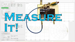
  • Measure characteristic capacitance, inductance, impedance, and phase velocity of a coaxial cable transmission line using nothing but a NanoVNA and some math.

Комментарии • 31

  • @anlpereira
    @anlpereira 4 месяца назад

    The best explanation I've seen how to understand why it is used 50 Ohm impedance cable. Thank you very much.

  • @ve6wo
    @ve6wo 3 года назад +2

    I enjoy your videos, please keep posting!

  • @vikrantvijit1436
    @vikrantvijit1436 2 года назад +1

    Thanks for valuable mathematical insights with total conceptual Clarity on electro-optical Networked vectors transmission line.

  • @hubercats
    @hubercats 2 месяца назад

    Great video. Thank you!

  • @aduedc
    @aduedc 2 года назад +3

    Zo=Sqrt(Zin_sc x Zin_oc) so simply measure Zin of open circuit and short circuit at any frequency, and you get Zo.

  • @johncourtney4084
    @johncourtney4084 Год назад +2

    Sir, thank you for this teaching. 2 things that I don't understand, how you came up with Vp=4piL, and speed of light I know as 3x10th8. Thank you for your help.

  • @SpinStar1956
    @SpinStar1956 8 месяцев назад

    Thank you and will look into your other videos!
    73… 😊

  • @SandeepKumar-jj7zi
    @SandeepKumar-jj7zi 2 года назад

    Nice demonstration, seems like nanovna is good as capacitance meter at low frequencies.

  • @stevexiao1488
    @stevexiao1488 Месяц назад

    Awesome! Just had a chance watching this 3 year old video. Could someone explain why Vp=0.67c?

  • @user-yl1tt9de3l
    @user-yl1tt9de3l 3 года назад +1

    THANKS !!!!!!!!!

  • @rdpdo
    @rdpdo 11 месяцев назад +1

    Hi, thanks for the video :-) I got a question : As the connector of NanoVNA is an SMA, its impedance is 50 ohm. So if we use a cable with not 50 ohm impedance, there will be mismatch between cable & connector. I would like to know if in this case the calculus you used is still valid for determining the caracteristic impedance of the new cable ? Thanks !

  • @tze-ven
    @tze-ven Год назад +1

    That beta is supposed to be phase constant. It denotes the change of phase per unit length along the path travelled by the wave. In your experiment, at 33MHz, the change of phase over the length of the cable is pi/2. Which means (pi/2)/L = beta, and hence leads to your equation beta * L = pi/2.

    • @jamesnagel2872
      @jamesnagel2872  Год назад

      Yes, I know. Did I give some indication I was confused somewhere?

    • @tze-ven
      @tze-ven Год назад +1

      @@jamesnagel2872 No you were not confused - you were good. I was not trying to lecture you, but to point out that you incorrectly mentioned that the beta is the Propagation Constant instead of Phase Constant. And also gave a simpler way to derive your final formula on the first line.

    • @jamesnagel2872
      @jamesnagel2872  Год назад

      @@tze-venAh, I think I see what you’re saying.
      You are correct that the terms “propagation constant” and “phase constant” are not the same thing. However, the distinction is subtle. The main difference is when the transmission line has attenuation. In that case, the propagation constant also accounts for attenuation. For lossless lines, however, they simplify into the same thing and are thus interchangeable.

    • @baghdadiabdellatif1581
      @baghdadiabdellatif1581 7 месяцев назад

      ​@@tze-vengreat work 👌👏👍

  • @RomanKuechler
    @RomanKuechler Год назад

    You would be a talented teacher. Interesstig video.

  • @baghdadiabdellatif1581
    @baghdadiabdellatif1581 7 месяцев назад

    Thank you

  • @tubosolinas
    @tubosolinas 11 месяцев назад

    Thank god for technology!Now we can consider a VNA a household item!
    😁

  • @j.w.8663
    @j.w.8663 Месяц назад

    Should you be doing this with your coax coiled in a tight loop?

  • @Tsachyl
    @Tsachyl 2 года назад

    Half way along a Smith chart is 90 degrees isn't it?
    In other words going from open (right side) to short (left side) takes half a circle or 90 degrees. so the cable's length is half of that or 45 electrical degrees because the signal travels forward & back.

  • @audriusmerfeldas7261
    @audriusmerfeldas7261 Год назад

    Dear James. I have tried to measure 50 Ohm cable with l=10.07m, 382pF total capacitance and 5,405MHz frequency where on Smith chart is short point. Regarding your calculations I am getting around 121 Ohm. Where I am wrong?

  • @rjordans
    @rjordans 2 года назад

    Thanks for the great explanation, quick but clear! One question though, you mention you're not measuring the inductance at low frequency as it varies too much. Does that make the value you now got specific to the 33MHz frequency at which you found the 1/4 wavelength propagation?

    • @jamesnagel2872
      @jamesnagel2872  2 года назад

      There is a "transition" bandwidth where the characteristic inductance varies, but it eventually stabilizes as the frequency gets very large. It happens because the skin depth is decreasing with frequency. Eventually, the skin depth gets so small that the current can be approximated as a thin sheet along the conductor edges, and this is where the inductance stabilizes.

  • @wendersonrodrigues8415
    @wendersonrodrigues8415 Год назад

    Thanks for the video. Why beta*l=pi/2? Could you explain this passage better? Why pi/2?

    • @miroslavm2503
      @miroslavm2503 Год назад +1

      Because when he dialed the marker on the smith chart to the short (closed) position, the first passage over the horizontal line, this is the frequency where the specific piece of cable that is hoked to the NanoVNA acts as a quarter line "stub" for the given frequency, so effectively you used the NanoVNA to find out the what is the frequency where that happens for this cable, where.
      So now that he knows that at this electrical length, beta*l, the cable is exactly pi/2, a quarter wave.

  • @germanjohn5626
    @germanjohn5626 2 года назад +1

    The nanoVNA can be set up to read out the impedance directly without going through a bunch of calculations.

    • @wd8dsb
      @wd8dsb 2 года назад +4

      Hi John, the nanoVNA can't directly measure the characteristic impedance of a feedline. There are numerous ways to determine (or approximate) the characteristic impedance of a feedline using the nanoVNA. There are easier methods using the nanoVNA but James looked at it from a classical transmission line theory approach which was indeed interesting (brought back memories from my college days studying transmission lines and propagation of energy).

  • @chuckcurtin
    @chuckcurtin 2 года назад

    Huh?

  • @N9IWJ
    @N9IWJ 10 месяцев назад

    I have no idea what your talking about? Been a ham for 45 years

    • @j.w.8663
      @j.w.8663 Месяц назад

      han is ok, at least you weren't a hun.