Thanks for the producing/posting the video. Although there are many videos about PLL circuits, there is no video explaining Capture/Lock ranges. For me, this video was quite helpful to understand them. Again, thanks so much !!
Very nice video, great detail and very understandable. I try to figure out how to replace a 1970s ASIC called TDA1000 in an vintage Studer Taperecorder. That is a phase detector and it seems that it is a custom IC.. may I ask you a question?
Pls forgive my ignorance on circuit. Can you pls tel me which component read and compensate the error signal out of low pass filter to stabilize a phase difference?
I believe the component you're looking for is the VCO or voltage controlled oscillator. I'm fairly new to this stuff as well, but as I understand it, if there's a phase difference, the phase detector will generate a signal which goes out to the low pass filter, which changes the voltage on the input of the VCO. This changes the frequency of the VCO's output, which is going into the phase detector. I hope that helps. And please don't ever feel bad for not knowing or not understanding something. It's very admirable that you're trying to learn and actively improving yourself. Just keep in mind that everyone was new to electronics at some point. What would be less forgivable is if you were unwilling to learn more despite asking questions. Cheers
Hello and thanks for watching. A UPS and mains don't need to synchronize as they aren't delivering power to the load simultaneously. It could synchronize the timing a computer though.
I've built a VFD tube digital timer that uses the 60 hz line frequency as reference. I've recently signed up for the solar farm power thingy. I've noticed that my clock is way more accurate. I noticed before that that the line frequency would vary throughout the day. Ultimately the clock would end up being accurate when all was said and done. It was as if they "made up" or corrected for inaccuracies during the day. Could be in my head.@@TheOffsetVolt
You have succeeded in confusing me even further. Like, I do understand that the units of RC are units of time. But, this is all way too complicated for me. Just give me a fricking circuit diagram, with some math, please. Yes, I know some calculus. It's still hard for a hobbyist to get it right. Thank you.
You need to just buy an experimenters breadboard and lose the fear of destroying components. A current limiting power supply is my best friend! The lives of many components have been saved by it. Fortunately the components here are cheap. I failed high school math at first, but at least I was really good at 9th grade math by the time I gradreated.

 Наука
Наука


This is a great video to go with W2AEW's video on PLLs. Thanks for taking the time to make this so we can all share in your passion for EE. Cheers.
Thanks for the producing/posting the video. Although there are many videos about PLL circuits, there is no video explaining Capture/Lock ranges. For me, this video was quite helpful to understand them. Again, thanks so much !!
Thank you for your tutorials. I'm looking forward to the frequency divider and multiplier using the PLL.
Finally got round to this. Great video! Looking forward to the next in the series. Curious why you didn't pick the CD4066 for the demo.
Thanks so much for this.
You're very welcome!
very interesting video, i have been working with some PLL circuits and this video helped me to understand some facts.. Thanks a lot
14:34 What if we wanted to generate a nice & clean SINE wave of a voltage-controlled frequency instead of those triangle/square waves?
Very nice video, great detail and very understandable. I try to figure out how to replace a 1970s ASIC called TDA1000 in an vintage Studer Taperecorder. That is a phase detector and it seems that it is a custom IC.. may I ask you a question?
For synchronization purpose, is the SNR required to capture a signal higher than the SNR required to hold the lock? Why?
How does the mixer work i see a rectifier in there
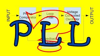
Pls forgive my ignorance on circuit. Can you pls tel me which component read and compensate the error signal out of low pass filter to stabilize a phase difference?
I believe the component you're looking for is the VCO or voltage controlled oscillator. I'm fairly new to this stuff as well, but as I understand it, if there's a phase difference, the phase detector will generate a signal which goes out to the low pass filter, which changes the voltage on the input of the VCO. This changes the frequency of the VCO's output, which is going into the phase detector.
I hope that helps. And please don't ever feel bad for not knowing or not understanding something. It's very admirable that you're trying to learn and actively improving yourself. Just keep in mind that everyone was new to electronics at some point. What would be less forgivable is if you were unwilling to learn more despite asking questions. Cheers
what if that 1.1 was a print error?
Excuse my ignorant comment but would a 5 percent wonder of the capacitor values do the same to your measurements ?
this is the type of circuit I'd use to sync a ups to the mains supply right?
Hello and thanks for watching. A UPS and mains don't need to synchronize as they aren't delivering power to the load simultaneously. It could synchronize the timing a computer though.
I've built a VFD tube digital timer that uses the 60 hz line frequency as reference. I've recently signed up for the solar farm power thingy. I've noticed that my clock is way more accurate. I noticed before that that the line frequency would vary throughout the day. Ultimately the clock would end up being accurate when all was said and done. It was as if they "made up" or corrected for inaccuracies during the day. Could be in my head.@@TheOffsetVolt
You have succeeded in confusing me even further. Like, I do understand that the units of RC are units of time. But, this is all way too complicated for me. Just give me a fricking circuit diagram, with some math, please. Yes, I know some calculus. It's still hard for a hobbyist to get it right. Thank you.
It's never my intention to confuse. I do appreciate your taking time to watch this video and to provide feedback.
You need to just buy an experimenters breadboard and lose the fear of destroying components. A current limiting power supply is my best friend! The lives of many components have been saved by it. Fortunately the components here are cheap. I failed high school math at first, but at least I was really good at 9th grade math by the time I gradreated.