Ladder Diagram Basics #2 (Safety Control Circuit)

HTML-код
- Опубликовано: 5 фев 2025
- This video walks you through one of your shop projects called Safety Control Circuit. Before you make a million comments on how bad this circuit design is... it is just a basic control circuit that helps students grasp the basics of how to design a rudimentary control circuit. Hope you enjoy it.


usefull. i think this control use for a machine that needed to push the button at same time to energized. like a press machine or any othe application base on the function.
Hi Megan, Yes, that is the premise of the circuit. However, this is just a primer to get students used to wiring an 8 pin relay. The controls for a press have to be completely fail safe. Here is another video on the "Anti-Tie Down" Circuit for a press. ruclips.net/video/5jT60c4UOyE/видео.html
it's good to see someone actually work to a specified checklist as opposed to just rambling on about how ladder works. puts it into a bit of perspective. thanks
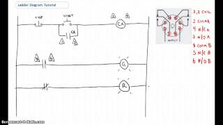
The step by step info and diagram including the real relay helps . This is better explained than my tech teachers did at school . Thank you!
I've been having trouble understanding this in my apprenticeship until now. Thanks man!
Pete you present a intermittent level class structure on circuitry (design, construction, component understanding and reasoning). It's very visual in scope, you only need ground level knowledge and a open mind. Please continue to enlighten us.
You’re way better than my professor ! Keep up the videos !
Graduated with instrumentation deg in 2012 and never got a job in the field, stayed doing residential and minor commercial. These videos are definitely “jogging” my memory!
Thank you, Mr. Pete, for all the tutorial videos you made.
Your a legend mate ... explained so well thank you
Sir thank you very much. Can you explain which terminal numbers for the relay and contactors connecting?
Thanks a lot for amazing explanation!
Thanks for all of the useful information. I find it easy to listen to listen and learn. Although I really like the references to "this bad boy", and showing your Canadian roots with "Beauty and Eh" Subscribing
now - Take off Eh !!
Thanks you hoser
This and these tutorials are what I have been needing #Thanks
Pete, thank you for the excellent explanation. I'm still learning more about motor control and my question is how about using both of CR2 normally open as aux. contact for PB2 and PB3 , jumper CR1 N/O to red lights?
It doesn’t specify, but I would wire both red lights in parallel after the second PB so you know if both are being held closed. Just my opinion, like you said, everyone does it their own way and the instructions are not very specific on certain things. 🙂
Do you know of any good references book that one can get to have handy at the shop to references to if one for get these steps. Thank you.
Excuse me Mr.Pete but can you please explain why you are using contacts 2 and 7 for both coils? Shouldn’t you have two relays, one for each coil? Also when you energize the coil (2&7) both N/O contacts (1&3) (8&6) will close turning on both red lights. I read some questions and comments regarding this but still did not see my mistake. Can you please elaborate.
Great tutorial!
These are very useful. Many thanks.
Great job!
Where you get these text boxes?
Pete, really nice explanation. please upload more tutorials
peter you are a very good guy teaching electrical control I really love and understand your puzles maybe dont cant explainme because Im not speak very good thankyou
Thanks for your videos!
Thank you very much Sir Pete
Hi, I didn’t get why with green lights you used only parallel without any contact from CR1, but with CR2 you made another and said that this only one way to do this. But what’s the difference?
Great video.
Great video
But I have a question !?
When energizing the coil of relay 1 then will both contacts of 1 and 2 close simultaneously ? (Since they have the same coil)
Yes 1 and 3, and 8 and 6 will change state and be closed simultaneously when the coil energizes.
I don’t see where is the second coil c2?
how do you connect a 400w 1ph capacitor run motor to a start/stop button?
hello brother
First of all thank you for this helpful session
I have questions .. what if we directly put realy's two NO contact connected from feeld then the NO contact then the two red lights
I think it also will work because the two lights wont switch on untill relay two is energized
For sure. That would work as well. Thanks for the feedback.
thank you so much
Honestly, i dont't understand of this idea and maybe i'm wrong, but: I think you are mixing ladder programming in PLC (LD) with electrical ladder diagram. (CR1/CR1 should have graphical symbols of electrical contacts instead of coils symbols which were used). Also, even if You stop pushing PB2/PB3, CR2 will be still energized because of CR1 hold contact, which will be still energized because of CR1 self-hold contact.
Please read my comment below the video before throwing shade.
Thanks good video
Nice video!
Thanks Pete.
Thank you!!
How can control relay 1 use COMMON 8 and NO 6? I thought you said in your last video both relays are independent? I thought CR1 can only use COMMON 1 and NO 3 and CR2 can only use COMMON 8 and NO 6.
Great tutorial, man. Appreciated.
Comm 1 goes with either 3 or 4, and Comm 8 goes with 5 or 6. Each relay (i.e. CR1 or CR2 has these two available contact pairs. Have a look at the diagram in the centre of the video beside the base for the contact placements.
Pete Vree thanks for the quick reply. I think you meant to type Comm 8 goes with both 6 and 5. I agree that each relay has two sets of available contacts NO and NC for each. I'm just pointing out in the video it looks like mixing CR2 contacts with CR1 because you marked CR2 as utilizing 1 and 3
No mixing up going on. CR1 has both 1 and 3 used on rung 2, and 8 and 6 on rung 3. CR2 has only 1 and 3 used on rung 4.
CR1 and CR2 both can use 1 and 3? I thought 1 and 3 are specific to CR1 only and CR2 has to make use of 6 and 5.
www.galco.com/images/mgcr/tdrsoxp-12v_cd.jpg
👍👍
Thanks!
BEAST!!!
Thank you sir
Thank
Nice
wire it up!