How to test ceramic and coil IF filters for eg 455 KC at a 10 KC wide bandwidth on their properties

HTML-код
- Опубликовано: 17 май 2024
- Please read the description first. A video where I show how to test ceramic (“crystal”) filters in the 455 KC range, used as IF filters with a bandwidth of (often) 10 KC (KHz) or 8 KC.
It is only a VLOG, but everything is told & showed in the video.
There are, by the way, many SW & MW radio circuits on my YT Channel. These are analog circuits for MW and SW. Thus: TRF, Superheterodyne and more, say a more simple heterodyne.
You can see, via everything showed in this video, if such a filter “works” and on what frequency and whether the ceramic (or coil filter) is ”active” (thus usable for a IF amplifier on, say, 455 KC) or “dead” (=not usable).
When the ceramic or coil filter does not want to oscillate in the FET test oscillator and (thus) does not show its resonance frequency (somewhere between 450 KC and 460 KC) it is dead and not usable.
The schematic & demo of this test oscillator is here:
• FET test oscillator si...
When you bridge the input of this test oscillator with a tuning capacitor in the order of 20-300 pF the circuit gets more versatile (=better tunable for test coils or test ceramic filters).
Though, of course, that extra capacitance will bring the frequency of the coil or ceramic filter that you are testing down or up (…! ). In general down, btw.
Apart from the stray capacitance in the FET test oscillator circuit and the cables. That is all classical radio theory: idea of parallel tuning, adding extra (or smaller) parallel capacitance to a tuned coil or ceramic filter.
The effect is, in general, in this circuit, not so big.
More important and the crux of the circuit is this: get the coil filter or the ceramic filter into resonance to see if it is healthy and usable.
In a definite circuit, where you want to put the crystal or coil filter on say 455 KC in, there is always input and output parallel capacitance, from all kinds.
Just like here in this test circuit. Thus, in practice, such an IF amplifier setup must/can be tested with a sine wave generator (the one showed here), with which you can tune the complete IF amplifier to its frequency, with that 10 KC or 8 KC bandwidth.
So this test gives a very reliable idea about the usability of IF ceramic filter X or Y or IF coil filter X or Y, when put into a definite IF amplifier in the 455 KC range, with its 8 or 10 KC wide (say) audio band, it is the “window” through which we look at the different (radio) signals that we receive on our antenna.
NB: the idea here is/was to receive AM modulated radio stations, though any IF amplifier can also be made to receive FM radio signals, with another type of detector, say the ratio detector. More about that on the www.
My You Tube channel trailer is here: • Radiofun232 on RUclips...
Type there the keywords that you like (e.g. radio/audio/amplifiers/test/filter/) in the “looking glass” = search function” and give “enter”. Via that you can find specific video’s (under the say 1500 published).
When you search, search always “NEWEST FIRST” to get the right overview.
You can also search via the “looking glass” on my Channel trailer via keywords like ”audio”, “radio”, “amplifier”, “filter”, “Shortwave”, “transistor”, “FET”, “oscillator”, “generator”, “switch”, “schmitt trigger” etc; so the electronic subject you are interested in.
My books about electronics & analog radio technology are available via the website of "LULU”, search for author “Ko Tilman” there. www.lulu.com/search?adult_aud...
I keep all my YT videos constant actual, so the original video’s with the most recent information are always on RUclips. Search there, and avoid my circuits that are republished, re-arranged, re-edited on other websites, giving not probable re-wiring, etc. Some persons try to find gold via my circuits. I take distance from all these fake claims. Upload 18 May 2024.
More info here (wobbulator for 455 KC) • how to make a 455 KHz ...  Наука
Наука


Silva mica capacitor disease is a pain with in old radio IF cans, its real annoying that they chose to put the cap inside 😞, but at least those could be repaired in most cases, cool video as always KO 😎👍👍
Thanks Steve!
Thanks 🙏
Great science. How do you keep everything organized?
Thanks, and yes that is an issue. After every experiment I clean up the workbench and all the components go back on stock.
Good video. Thanks.
Thanks Ron.
Very interesting, Thank You! Can you sweep through a ceramic filter to measure its bandwidth?
Yes, it is possible, when you connect the ceramic filter (say 455 KC) at the output of the test oscillator, at the same time connect a 455 KC coil filter at the input of the test oscillator. Scope + counter to the output. When the coil filter is tuned (by moving the core in-out) you can see where the best resonance peak is. Thanks. 19 May 2024.
More info here ruclips.net/video/P3zzuf9p8hI/видео.htmlsi=5nr39s1gdRC893M1
We can't test these vlf receivers here because of not available signal even MW band . But very lot FM channel here in Sri Lanka. I think very phone, Bluetooth speaker set have FM receiver. How these Small receiver work ? . Shell we start experiment with FM band ? I know you have vlogs in FM receiver.
Yes, I know that issue. Like you know, you told it, I have, once, published a schematic of a simple FM radio with the TBA 120 IF amplifier and FM detector chip.
Video link
ruclips.net/video/F5whmoEcbn0/видео.html
I think that is all that I can say about making a simple FM radio between (say) 88 MC and 110 MC.
Of course it needs a ratio detector (FM detector), but everything is showed in that video. Thanks.
Many video's about how a FM detector works are on YT. 20 May 2024.
All info is (earlier video's about FM/TBA 120 etc) is in links in the description of the named vid. Its video link is here
ruclips.net/video/F5whmoEcbn0/видео.html
20 May 2024
Sometimes those 455kHz transformers don't have an internal capacitor but an external one. Good demonstration though. 😊
True. Thanks Barry.
Does not show much! Filters work with specific load...
Yes, surely, always. Much more info in tens of other video's on my YT Channel. You can search there via my channel trailer "Radiofun232 on RUclips", via the looking glass (search option) when you type there keywords like "IF, IF amplifier, radio, radio technology, shortwave, filter, wobbulator", etc. What you adress is a common comment of viewers when they are looking at my filter schematics, both for audio and HF (radio applications). The input-and output impedance and the effects of that on the bandwidth, here say 10 KC or 8 KC in a radio application (superhet). I have payed, many times, attention to the question that you propose and that is a right question, by the way. But, anyway, this video is also OK in this regard. It shows if a ceramic filter in the 455 KC order is healthy, thus usable in a IF amplifier, of whatever kind (FET, BJT). Of course, in all cases, all IF filters amplifiers in a superhet. radio IF amp. must be tuned, so that the IF amp. has a proper bandwidth. More info in the video's on my YT Channel. Thanks 20 May 2024.
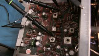
Look at his test circuit. Its output goes to a frequency counter of 50 ohm input.