A few questions: 1a, b, c) In the circuits @ 4:00 and 4:30, you 1st assume the voltage @ the Zener cathode is as rated, then the voltage drop across R1 determines It, and the (Zener) voltage drop across RL determines IL, correct? But in actuality if Iz is only 1.1 mA (regulation lost, 4:30), the voltage @ the Zener cathode is likely less than it's rated voltage because, well, it's not in the voltage region where it's conducting much, right? (Is that current figure larger for a larger wattage Zener, or is the ratio of Iz : IL the only significant factor?) (I have a bunch of 5 watt Zeners on hand.) 2) How do you determine "sufficient" Zener current? Just figure Iz and IL about equal? 3) If I don't need regulation and just need a voltage clipper, then I mainly need to worry about overcurrent (power rating) in the Zener and RS, correct? (As in a lighting app off a battery, where visible observation the light is dimming can serve as a warning the battery is getting low, potentially saving a battery from damage, but I want some protection should the charging circuit get a little enthusiastic about voltage charging the battery -- I've measured 14.7 volts @ the battery of my car with the engine running.) 4) If "pushing" the Zener's power rating, heat sink it or get a higher power Zener, right? 5a, b) Zener diodes in the range of 5v - 6v are usually the most temperature stable Zeners? One probably should just use a voltage reference chip if really good regulation is needed, but 2x 6v Zeners in series should double power capacity and be more stable than a 12v Zener, correct?) 6) Somewhat the same question as "3" for the Zener - pass transistor circuit @ 10:00, but now add the transistor's current rating? 7a) If hfe was less, say, 50, the pass transistor circuit @ 10:00 still works much the same, but base current is double? 7b) (What I'm really trying to get to and I'm not sure I'm looking at this correctly!) : If I use a well heat sunk TIP31C with Hfe = 50 as a pass transistor (the specs from various mfg.'s and "classes" vary from Hfe = 10 - 100 even before operating temperature and current throughput is considered), and if RL = 11 ohms (making IL ~500 mA), my base current would be just over 11 mA? Seems like that would be ok if I decrease Rs to 100 ohms? Again, I'm looking for voltage limiting to the load more than true regulation. Thanks!
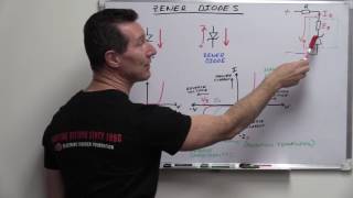
12:42/16:48 a transistor series regulator with a zener connected to the base. STILL used instead of a switching supply because the switcher ripple and spikes, can be a problem for some circuits. be careful ! ! IF the regulated voltage at the emitter undergoes an accidental short circuit, the base will be held to the zener voltage , causing the base current to burn out the transistor ! observerms
An excellent application based video. i have a question: Lets say if we connect the the zener diode between solar panel and photo transistor. Phototransistor is connected to a gate of the mosfet with Vgs 16V max. the mosfet is used to drive actuator requiring minimum of 8V and max of 10 V dc. Photo transistor is with Vce 50V and Vbe 7V max. my question is do i really need zener diode between the panel and photo transistor. if yes how does the circuit will be? My application is that when the light falls on the photo transistor it will be on and provide a voltage to the gate which connectes my mosfet to the actuator. Rl in video what is that is it the load resistance against zener or the load.
Haha, forgot one other question about the pass transistor circuit @10:00: If the source voltage (Vs) falls below the Zener voltage, then the transistor emitter voltage will "track" the source voltage less .6 - .7 volts, right?
I have a 9vdc, 350 mA power supply. With no load the PS shows about 13v. When i put a 9v zener across it as in your diagram, with no resistors, it will power a chorus effect for guitar with the zener clamping the PS to 10.5 volts and the LED on the chorus pedal burning brighter than with a 9v battery. To bring the current down and LED less bright, and clamp closer to 9vdc, do I increase or reduce the value of RL and/or RS? Thanks.
Hello, I would have two questions regarding the last circuit. 1) Is this a monitoring circuit for a 12V charging circuit? 2) The voltage drop across the pnp transistor (2N2907) is the Vcesat?
It's for illustration purposes. If these were connected in the real world all of the measurements would vary even if the same circuit was wired the same way multiple times with different parts the measurements would vary somewhat. That something you won't learn with circuit simulators. The current divides between the zener and transistor.
The output voltage is 5.05V divided by 50 Ohms = 101mA. The hfe of the transistor is 100 so divide 101 by 100 ~= 1mA. In reality we have the 100mA from transistor plus 1mA base current. If a higher current is needed then more base current is requires - taken from the zener current. There is a limit on this.
@@michaelfray9608 There is a circuit on All About Circuits forum where a MOSFET is used in a power supply circuit, but with a TL431a as a sort of adjustable precision diode. I think you could make it work with a zener, but it's getting away from being a simple circuit. See "Amplified(?) voltage limiter design (behavior at sagging input voltages)". Note that this is by design not a true regulator, it is a LDO supply voltage limiter, for lopping off excess voltage in an automotive app when the car battery starts getting above 13v. However, I think the design probably could be simplified for a regulator?
Great video, but people, please don't use any of these circuits in actual applications. These are absolutely wasteful, and there's better ways to get both voltage regulation, and measure the battery voltage. Zener circuits like these are very old, and outdated. I can provide some good alternatives if needed/anyone is interested. Cheers.
This maybe one choice you have dealing with high voltages generally over 60v. There's also a 700mA variable linear regulator that can deal with 125v maximum input voltage, the TL783CKC.


A super video, as are the others. Very clear, concise and easy to follow.
really great video. anyone could follow your explanations. very concise and well done
very good tutorial.i guess u must be a great teacher.keep it up sir and thanks a lot..
Extremely useful for electronics student.
A few questions:
1a, b, c) In the circuits @ 4:00 and 4:30, you 1st assume the voltage @ the Zener cathode is as rated, then the voltage drop across R1 determines It, and the (Zener) voltage drop across RL determines IL, correct? But in actuality if Iz is only 1.1 mA (regulation lost, 4:30), the voltage @ the Zener cathode is likely less than it's rated voltage because, well, it's not in the voltage region where it's conducting much, right? (Is that current figure larger for a larger wattage Zener, or is the ratio of Iz : IL the only significant factor?) (I have a bunch of 5 watt Zeners on hand.)
2) How do you determine "sufficient" Zener current? Just figure Iz and IL about equal?
3) If I don't need regulation and just need a voltage clipper, then I mainly need to worry about overcurrent (power rating) in the Zener and RS, correct? (As in a lighting app off a battery, where visible observation the light is dimming can serve as a warning the battery is getting low, potentially saving a battery from damage, but I want some protection should the charging circuit get a little enthusiastic about voltage charging the battery -- I've measured 14.7 volts @ the battery of my car with the engine running.)
4) If "pushing" the Zener's power rating, heat sink it or get a higher power Zener, right?
5a, b) Zener diodes in the range of 5v - 6v are usually the most temperature stable Zeners? One probably should just use a voltage reference chip if really good regulation is needed, but 2x 6v Zeners in series should double power capacity and be more stable than a 12v Zener, correct?)
6) Somewhat the same question as "3" for the Zener - pass transistor circuit @ 10:00, but now add the transistor's current rating?
7a) If hfe was less, say, 50, the pass transistor circuit @ 10:00 still works much the same, but base current is double?
7b) (What I'm really trying to get to and I'm not sure I'm looking at this correctly!) :
If I use a well heat sunk TIP31C with Hfe = 50 as a pass transistor (the specs from various mfg.'s and "classes" vary from Hfe = 10 - 100 even before operating temperature and current throughput is considered), and if RL = 11 ohms (making IL ~500 mA), my base current would be just over 11 mA? Seems like that would be ok if I decrease Rs to 100 ohms? Again, I'm looking for voltage limiting to the load more than true regulation.
Thanks!
12:42/16:48 a transistor series regulator with a zener connected to the base. STILL
used instead of a switching supply because the switcher ripple and spikes, can be a problem for some circuits.
be careful ! ! IF the regulated voltage at the emitter undergoes an accidental short circuit,
the base will be held to the zener voltage , causing the base current to burn out the transistor !
observerms
An excellent application based video. i have a question:
Lets say if we connect the the zener diode between solar panel and photo transistor. Phototransistor is connected to a gate of the mosfet with Vgs 16V max. the mosfet is used to drive actuator requiring minimum of 8V and max of 10 V dc. Photo transistor is with Vce 50V and Vbe 7V max.
my question is do i really need zener diode between the panel and photo transistor. if yes how does the circuit will be? My application is that when the light falls on the photo transistor it will be on and provide a voltage to the gate which connectes my mosfet to the actuator.
Rl in video what is that is it the load resistance against zener or the load.
Awsome explanation
Great job Lewis!!
Do you have a circuit that uses a mosfet instead of a transister?
great video... Do you have more tutorial videos?
Haha, forgot one other question about the pass transistor circuit @10:00: If the source voltage (Vs) falls below the Zener voltage, then the transistor emitter voltage will "track" the source voltage less .6 - .7 volts, right?
The source voltage must always be higher, by several volts, than the output voltage.
I have a 9vdc, 350 mA power supply. With no load the PS shows about 13v. When i put a 9v zener across it as in your diagram, with no resistors, it will power a chorus effect for guitar with the zener clamping the PS to 10.5 volts and the LED on the chorus pedal burning brighter than with a 9v battery. To bring the current down and LED less bright, and clamp closer to 9vdc, do I increase or reduce the value of RL and/or RS? Thanks.
What are you doing? 13V is regular under no load in cheap power supplies. Only use a zener with a resistor. What voltage do you want out?
9vdc out.
@@ab9957 What is your input voltage? You can't go by 13V at no load input. Use at least 112V at 1 amp.
Nice video!
Hello, I would have two questions regarding the last circuit.
1) Is this a monitoring circuit for a 12V charging circuit?
2) The voltage drop across the pnp transistor (2N2907) is the Vcesat?
No. It merely switches in the battery voltage to be measured. A separate current monitor can be used.
The 2N2907 transistor is obsolete.
Very good tutorial. Thank you.
I have plenty of them. Use any PNP you want. They are all over the place on Ebay - 50 for $3.00 Thanks.
They're still being sold by element14.
In the first diagram with the transistor 12:48, how do determine only 1ma goes through the transistor base and 28 is sunk by the zener?
It's for illustration purposes. If these were connected in the real world all of the measurements would vary even if the same circuit was wired the same way multiple times with different parts the measurements would vary somewhat. That something you won't learn with circuit simulators. The current divides between the zener and transistor.
Hi, sorry the question , i'm learning electronics but i can't understand how you can calculate 1mA in the transistor base and 28mA in the zener diode.
The output voltage is 5.05V divided by 50 Ohms = 101mA. The hfe of the transistor is 100 so divide 101 by 100 ~= 1mA. In reality we have the 100mA from transistor plus 1mA base current. If a higher current is needed then more base current is requires - taken from the zener current. There is a limit on this.
@@LewisLoflin Oh..now i understand. thanks a lot for your time and congratz for the quality of the contents you post here on youtube.
Can i use a mosfet as a pass transistor in this circuit.
No. MOSFETs are voltage-operated bipolar transistors are current operated.
@@LewisLoflin thanks much
@@michaelfray9608 There is a circuit on All About Circuits forum where a MOSFET is used in a power supply circuit, but with a TL431a as a sort of adjustable precision diode. I think you could make it work with a zener, but it's getting away from being a simple circuit. See "Amplified(?) voltage limiter design (behavior at sagging input voltages)". Note that this is by design not a true regulator, it is a LDO supply voltage limiter, for lopping off excess voltage in an automotive app when the car battery starts getting above 13v. However, I think the design probably could be simplified for a regulator?
ALSO KNOWN AS A ZENOR FOLLOWER CIRCUIT
Nice sir
Hi! Can I ask you for pdf version of tutorial? Thanks.
Best regards, Jan.
See www.bristolwatch.com/ele/zener_power_supply.htm
9:37 Ouput voltage 5.05V ???
must 5.6V+Vbe
Great video, but people, please don't use any of these circuits in actual applications. These are absolutely wasteful, and there's better ways to get both voltage regulation, and measure the battery voltage. Zener circuits like these are very old, and outdated.
I can provide some good alternatives if needed/anyone is interested. Cheers.
I made that clear on my website these are for learning electronics, not for use in a commercial product.
This maybe one choice you have dealing with high voltages generally over 60v. There's also a 700mA variable linear regulator that can deal with 125v maximum input voltage, the TL783CKC.