In 10 minutes, you made me understand what I couldn't in 4 years of engineering! OpAmps no longer look like magic to me!! You are brilliant, Sir. I can never thank you enough.
For some reason, this video I stumbled upon at 3am on (another) sleepless night has just hit the spot. You always just find these videos that either repeat things you already know, or are beyond comprehension complicated and you are lost in the first two minutes. There are always these thoughts where I think „yeah it probably works like that“ but I just never really believe it until someone says it out. This Video cleared a LOT of those up. Thank you so, so much.
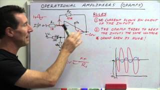
This is the best intuitive analysis of an Op Amp circuit I've seen. No complex math, just an understanding of a few simple concepts. The rules of an ideal Op Amp, Ohm's Law, and Kirchoff's voltage and current laws.
This is priceless interview material. In several job interviews I've been asked to analyze the large-signal behavior of different opamps circuits with no equations and this technique has helped me A LOT! Thanks for posting Dan!
If you need something as basic as this on youtube to give you an advantage in a job interview then your training and experience is way below what you need to do that job. Youd be like the aeronautical engineer that thought its ok to cut heat traeted aliminium by laser cutting. Education these days is so poor if it results in qualified people that have that level of knowledge
This guy helped me understand this in 4 minutes, vs my professor who teaches this in an hour and you are still confused afterward. Thank you sir, will be coming back to see more videos!
Thank you very much! Up till now I just remembered the formulas for different types of basic opamp circuits, but now I actually understand where they came from and am able to tackle more complecated circuits.
Superb explanation! This came at a good time for me, I just finished my Op-Amps class and I'm still wrestling with the circuit analysis. I've been falling back on the algebra formulas, but they don't provide real understanding. The steps 1, 2 and "3 with a twist" are great. Your approach, using the three op amp rules and Kirchoff's Law, provides clear and easy to visualize insight. I've looked at many op-amp tutorials, and this is my favorite, thanks for taking the time to share your knowledge.
I usually never write comments on youtube videos but this was a great video. It made so much sense and it made something that looks complicated seem very simple. Thank you so much!!! I have gained back some confidence in my circuit solving skills. You should make more circuit solving videos, a video on how to design op amps according to a specification would be great.
Hi Dan, Just to say that I'm 2 minutes into your video and I've paused it just to write this comment. EXCELLENT introduciton, to the point and the 3 rules here, more importantly the first one that I didn't really know about, are just great! I have seen dozens of Opamp videos, but no-one has put rule 1 into plain English: OBVSIOULY this is of GREAT help in understanding the OVERALL CONCEPT. EXCELLENT, I've learned something today, and I'm happy!!!! Keep it up!
WOW! Absolutely amazing tutorial. I'm currently back in school as a non-trad, and we're working with OpAmp circuits in my upcoming Electronics lab, and when I heard that that would be our second lab, I thought 'ACK! I don't know much about OpAmps, other than that they can be a big stumbling block', and having watched this, I feel much less intimidated. Thank you so much for posting this, this is absolutely amazing, and I'll probably be coming back to your channel as the semester goes on!
Simple, yet very helpfull tut. Thanks a lot. I loved that you mentioned that there is no current in the output too. It is very important sometimes for solving the circuit.
Rule #2 is actually a consequence of Rule #3 IF there's a feedback that applies the output to the input until the two inputs are equal. Btw, great explanation
I really liked the video! I'm going to a 2-year tech school for electronics. I'm in my second semester of my first year. The way they do it here is split each semester into 3 5 week modules. This module (as well as the previous one) is all digital stuff, so I'm a bit rusty with calculating these circuits. Again, thanks for the video! It's a nice refresher!
This is a great video and you have a talent for conveying challenging concepts. It would be wonderful if you created more videos like this about analog electronic circuit design!
I've had several people challenging me to solve this circuit or that circuit. Let's not do that. Use the technique I show you here to solve the circuit you have in mind. Assume a voltage and see what happens. You can always start with the Vout at one of the rails and see where that leads you.
Dan Bullard You assumed there is the same voltage on both inputs in each case (as per your rule 2) and then found a greater voltage on the output in each case? rendering your rule 2 redundant as you stated yourself? This makes no sense? how can you have no differential between inputs(considering firstly that this does NOT use negativr feedback) (ie. 2V on each input and then magically have 10V on the output? again reaching that conclusion by assuming one input is the same as the other "unless the output is greater" then finding that the output IS greater and still taking 10V as the legitimate answer??
Thanks Dan for the very clear explanation. One suggestion would be to label the appropriate ref designators for the 3rd case equivalent circuit so the “student” can quickly identify which resistor is which.
Sir this video you have been taken is just insanely good, is there any chance you could do RL, RC ,RLC and Op-Amp with RL, RC, RLC. I could not believe my eyes, how clear can someone teach something that shot time. Much love.
Not likely, but I appreciate the comments. RL&C are just not that simple, although I did do a video on RC coupling.ruclips.net/video/GGAt6N-Pz9w/видео.html
Dan, this video is so good. I have seen many online tutorials on op amps and this is by far the best. Why don't you upload more like this? You would become very popular very quickly. We need more lectures of this quality there are so few about.
Good video. You could also mention that rule 2 applies only to closed circuits, where the output connects in some way with the - input, and the impedance therein does not prevent the max output voltage from being too low to match the input.
THANKYOU SO MUCH DAN...U SAVED MY LIFE...GOT MA FINALS 2MRW...ELCTRINCS...I DONT EVEN KNW THIS CONCEPT OF OP AMPS TILL NOW I HAD SOME LIGHT LOL...CHEERS MAN!! THANKYOU SO MUCH...U'R BEST!!
I recall from a discussion with EE that when an op amp is used as a simple DC signal amplifier, the internal resistance of the input device itself (like a sensor coil) has to be included as part of total input resistance at the summing point. In that case the gain would actually be the feedback resistance / total input resistance.
You were showing the switch at 2v which corresponded to a Vout of 10v. You referenced back during this time to the initial switch position at 1v with a Vout of 5v.
Just an adjustment to your rules. If there is output feedback to the inverting ( - ) input, rule 2 applies unless V(out) is beyond the range of the rails or source.
Yeah, but... It's easier to just let someone do the analysis ignoring what might be feeding back to what. What happens when you have both negative and positive feedback? Who knows, until you analyze it.
Very Good Circuit Analysis ,The Way you say it ,it shows you are a teacher ,,I disagree with some of it ,but bottom line VERY Good Troubleshooting . and thats how we learn from each other .
Here's a question about the "ideal" op amp. According to the ideal model, the open loop gain is infinite and any input would also cause the output to saturate or go full conduction. In that case, the op amp would act like a switch -IE- a solid state relay and any input would case it to turn on with full conduction. Even with negative feedback, it seems the op amp would still behave as a switch rather than a linear device and the whole system would be unstable and prone to oscillation. Accordingly, my opinion for modeling the ideal op amp is to assume the it has a very high (but not infinitely high) gain so it still behaves as a linear device, but not have the characteristic of a switch.
I think that negative feedback would keep things in check automatically, no matter what the gain is. Any tiny difference would instantly be corrected. Now, toss a capacitor into the mix and watch it oscillate because the feedback can't get there fast enough especially when the gain is infinite.
Dan Bullard Here's a practical experiment that might verify whether or not a device with an infinite DC gain will be stabile. Get a DC/DC solid state relay (a device that turns full on with a small input signal) like the one in the link below and connect it as an inverting amplifier. That is the + output is tied back to the - input so the output is 180 degrees out of phase with the input. Then apply several different levels as the turn on signal and see if the output is in fact a linear function of the input. www.crouzet-ssr.com/english/products/_gndc.shtml In my opinion, it's a good idea to avoid obscure mathematical constructs that have "infinite" quantities which can lead to confusion in a practical analysis. That's why the concept of a mathematical "limit" was introduced because infinite quantities should not be inserted in equations such as the one for amplifier gain. Accordingly, it would be better just to say the ideal op amp has a gain that approaches - but never reaches- infinity.
Thanks, a very helpful video. But could someone explain the purpose of R4 & R5 or are they simply not needed if there's no current flowing through them and no voltage drop? Thanks in advance.
R4 and R5 are just current limiting resistors in case something bad happens to the Op Amo.. That and in this case it allows me to make the point about Rule #1.
@@DanBullard I recently suffered some minor brain damage and lost a lot of my maths abilities. I'm slowly relearning them, so I find electronics calculations really useful. Thanks again.
I might be a little bit too late to join the party 😄 I appreciate the clear explanation and detailed solution you provided. Sometimes we all forget that electronics is not that complicated and that all circuits can be handled by simply adhering to a few basic laws. I have a question, and I would greatly appreciate it if you could help me understand the design decision: what is the purpose of R4 and R5 in this circuit?
R4 and R5 are typically placed there to keep the current down to a minimum if the Op Amp fails, but in this case they are used to trick the observer, to see if they understand that an Op Amp consumes no current on the inputs. It's a standard ploy imposed on Employee Applicants.
@@DanBullard I appreciate your response. They were current-limiting resistors in my mind. Although it's a wonderful concept, I've never utilised them in any designs. In my subsequent design, I'll give it a shot.
Really good and easy to understand .. can you please upload some more videos .. on most basic devices in electronics... opamps, transistors, mosfets ... thanks and will greatly appreciate your help ....
GREAT tutorial. I have to admit, I didn't understand most of it. I've got a probable reverb recovery unit op amp problem in my Marshall guitar amp, and I am hoping if you could walk me through testing the circuit, or at least the op amps, in an effort to identify the defective component? I've got a link to the schematic, and a multimeter. Should I just start at pin #1, measure the voltage, then try to use this video to solve for the other pin, and measure them..? Thanks
Robert McBride I think it would take a bit more than that. One thing you can do is check the voltage difference between the two inputs, pins 2 & 3 if I am not mistaken. They should be the same voltage if everything is OK. Give me the link to the schematic and I can see if I can walk you through testing it.
Should the ground line for the op amp circuit be connected to the chassis ground which is the green wire (or safety earth ground) for the AC power supply? I've seen many permanent installations (such as seismological and meteorological stations) in which the op amp's ground line was also connected to the green wire but some others did not have a connection. However it seems that the amp's ground itself probably should not be connected to the green wire because any current through the green wire would create a voltage and make the amp's ground line subject to erratic ground reference. Furthermore, the voltages in op amp circuits themselves are so low that there's no safety issue and only the chassis of 120 VAC power supply would need to be earth grounded.
Dan Bullard Although the IC itself doesn't have a ground pin, the non-inverting input is grounded (to provide a reference point for the differential input) and the external load at amp's output (a galvanometer for example) also has a return to ground. Seems that connecting the chassis ground wire to the ground line that's also used for the complete circuit might introduce noise.


Twelve years old and still one of the best Op Amp explanations out there. Awesome my fellow USN ET brother! ;-)
In 10 minutes, you made me understand what I couldn't in 4 years of engineering! OpAmps no longer look like magic to me!!
You are brilliant, Sir. I can never thank you enough.
Thank you! I used to teach at a school where we analyzed circuits like that every day. The students got really good at op amps. Glad I could help.
That's concerning.
OK, OK! It was my first one! I will do some more and have already started a positive feedback version. Stay tuned!
Thank you. Respect from india
Thanks alot I really appreciate you from KENYA
Very Good tutorial Dan, hope you can still share some more of your technical knowledge.
Ok, this is PURE GOLD, to me at least. This is the simplest explanation ever I heard.
For some reason, this video I stumbled upon at 3am on (another) sleepless night has just hit the spot. You always just find these videos that either repeat things you already know, or are beyond comprehension complicated and you are lost in the first two minutes.
There are always these thoughts where I think „yeah it probably works like that“ but I just never really believe it until someone says it out.
This Video cleared a LOT of those up.
Thank you so, so much.
This is the best intuitive analysis of an Op Amp circuit I've seen. No complex math, just an understanding of a few simple concepts. The rules of an ideal Op Amp, Ohm's Law, and Kirchoff's voltage and current laws.
Sir, you helped me overcome 25 years of dread for op-amps... i can never thank you enough.
My fours years at engineering school could not make me understand what you did. Thanks for this wonderfule content.
This is priceless interview material. In several job interviews I've been asked to analyze the large-signal behavior of different opamps circuits with no equations and this technique has helped me A LOT! Thanks for posting Dan!
If you need something as basic as this on youtube to give you an advantage in a job interview then your training and experience is way below what you need to do that job.
Youd be like the aeronautical engineer that thought its ok to cut heat traeted aliminium by laser cutting.
Education these days is so poor if it results in qualified people that have that level of knowledge
@@davefoord1259 based
Posted 8 years ago and it is more helpful than other sources i have been read and watched. Thank for this video I learned a lot about op amp
This is the first time I've fully understand how op amp works. Thanks a lot!
You are very welcome!
Great tutorial! I went out and bought a HP6235 power supply just so I could recreate this lesson. It makes so much more sense now. Thanks Dan.
This guy helped me understand this in 4 minutes, vs my professor who teaches this in an hour and you are still confused afterward. Thank you sir, will be coming back to see more videos!
Thank you very much! Up till now I just remembered the formulas for different types of basic opamp circuits, but now I actually understand where they came from and am able to tackle more complecated circuits.
Superb explanation! This came at a good time for me, I just finished my Op-Amps class and I'm still wrestling with the circuit analysis. I've been falling back on the algebra formulas, but they don't provide real understanding. The steps 1, 2 and "3 with a twist" are great. Your approach, using the three op amp rules and Kirchoff's Law, provides clear and easy to visualize insight. I've looked at many op-amp tutorials, and this is my favorite, thanks for taking the time to share your knowledge.
I usually never write comments on youtube videos but this was a great video.
It made so much sense and it made something that looks complicated seem very simple. Thank you so much!!!
I have gained back some confidence in my circuit solving skills.
You should make more circuit solving videos, a video on how to design op amps according to a specification would be great.
Ideal op virtual ground (v+=v-)
Find the Circuit vo is not complexe and then v?v? .. ! Great explain Sir 😊
Hi Dan,
Just to say that I'm 2 minutes into your video and I've paused it just to write this comment. EXCELLENT introduciton, to the point and the 3 rules here, more importantly the first one that I didn't really know about, are just great! I have seen dozens of Opamp videos, but no-one has put rule 1 into plain English: OBVSIOULY this is of GREAT help in understanding the OVERALL CONCEPT. EXCELLENT, I've learned something today, and I'm happy!!!! Keep it up!
WOW! Absolutely amazing tutorial. I'm currently back in school as a non-trad, and we're working with OpAmp circuits in my upcoming Electronics lab, and when I heard that that would be our second lab, I thought 'ACK! I don't know much about OpAmps, other than that they can be a big stumbling block', and having watched this, I feel much less intimidated. Thank you so much for posting this, this is absolutely amazing, and I'll probably be coming back to your channel as the semester goes on!
Thank you!
Simple, yet very helpfull tut. Thanks a lot.
I loved that you mentioned that there is no current in the output too. It is very important sometimes for solving the circuit.
Really great explanation of working through this op-amp circuit. Thank you very much for taking the time to do this. Cheers
I wish you had more of these, but then again, this video was a quantum leap in my understanding of op amps
The way you did this numerical is fantastic and probably the best
Very logical step by step explanation. It has been a while since I worked with Op Amps and I am boning up for job related testing.
Thanks! I wrote it to help a friend bone up for a test at GE She passed the test and got the job!
Great video Dan! You are really good at teaching these concepts in a simple and elegant manner. Thank you for making this, please make more!
Those people who dislike this...why? This explanation is so clear and superb!
Brilliant, very clear, a good speed, a good amount of repetition/variance. Wish this was around when I was learning.
Rule #2 is actually a consequence of Rule #3 IF there's a feedback that applies the output to the input until the two inputs are equal. Btw, great explanation
you really know how to teach things. after all research, I think I really understand op amps now. thanks a lot
I really liked the video! I'm going to a 2-year tech school for electronics. I'm in my second semester of my first year. The way they do it here is split each semester into 3 5 week modules. This module (as well as the previous one) is all digital stuff, so I'm a bit rusty with calculating these circuits. Again, thanks for the video! It's a nice refresher!
One of the clearest explanations I have heard so far. Nice Vid Dan
+[Dan Bullard] , you sir were the first one to break it down easy enough for me to understand this, thank you very much
Thank you for comming and sharing with me !
Thank one million !
Holy shit! This explanation was the one I was waiting for! So easy to understand
This is a great video and you have a talent for conveying challenging concepts. It would be wonderful if you created more videos like this about analog electronic circuit design!
My newest -ruclips.net/video/UkfRYfOj3e0/видео.html
I've had several people challenging me to solve this circuit or that circuit. Let's not do that. Use the technique I show you here to solve the circuit you have in mind. Assume a voltage and see what happens. You can always start with the Vout at one of the rails and see where that leads you.
Dan Bullard You assumed there is the same voltage on both inputs in each case (as per your rule 2) and then found a greater voltage on the output in each case? rendering your rule 2 redundant as you stated yourself? This makes no sense? how can you have no differential between inputs(considering firstly that this does NOT use negativr feedback) (ie. 2V on each input and then magically have 10V on the output? again reaching that conclusion by assuming one input is the same as the other "unless the output is greater" then finding that the output IS greater and still taking 10V as the legitimate answer??
I am wondering if by 'voltage supply' he means the plus/minus 10V attached to the op amp
Yes, the power supply
Thanks Dan for the very clear explanation.
One suggestion would be to label the appropriate ref designators for the 3rd case equivalent circuit so the “student” can quickly identify which resistor is which.
Thank you very much! This has made Op Amps infinitely easier!
Like an opamps open loop gain hehe
That was extremely clear and helpful. Thanks for posting this video.
Sir this video you have been taken is just insanely good, is there any chance you could do RL, RC ,RLC and Op-Amp with RL, RC, RLC. I could not believe my eyes, how clear can someone teach something that shot time. Much love.
Not likely, but I appreciate the comments. RL&C are just not that simple, although I did do a video on RC coupling.ruclips.net/video/GGAt6N-Pz9w/видео.html
Dan, this video is so good. I have seen many online tutorials on op amps and this is by far the best. Why don't you upload more like this? You would become very popular very quickly. We need more lectures of this quality there are so few about.
Good video. You could also mention that rule 2 applies only to closed circuits, where the output connects in some way with the - input, and the impedance therein does not prevent the max output voltage from being too low to match the input.
That was a great video. I immediately subscribed after watching this so that I do not miss your videos. That was just great.
Thanks! I love how clearly you explained the method (it's exactly what my prof seems incapable of doing)
Dan! you saved a lot of time ... instead of reading and understanding, i simply understood everything... :D thanks a lot...
Please upload more videos
We went from 5V out to 10V out. That's 5V. That change happened with a 1V change on the input hence the gain of 5.
You just save my ass for my tomorrow exam! Thanks
Alma Brew i hope he save my ass too cuz i have an exam tomorrow xD
a bouchra II Good luck!
Awesome video sir how easily you solve the problems sir.Hats off to you sir.Thanks for uploading this video.Sir please upload some more numericals.
thank you. you are a life savior! I ' ve got an exam in two days and things begin to clear up. Can't wait for your next video :D
Regards, Vlad
This was the one of best video i found,thanks ❤
i never comment on youtube videos, but this was so helpful and articulately explained- THANK YOU!
THANKYOU SO MUCH DAN...U SAVED MY LIFE...GOT MA FINALS 2MRW...ELCTRINCS...I DONT EVEN KNW THIS CONCEPT OF OP AMPS TILL NOW I HAD SOME LIGHT LOL...CHEERS MAN!! THANKYOU SO MUCH...U'R BEST!!
I recall from a discussion with EE that when an op amp is used as a simple DC signal amplifier, the internal resistance of the input device itself (like a sensor coil) has to be included as part of total input resistance at the summing point.
In that case the gain would actually be the feedback resistance / total input resistance.
Yes, but sometimes it's hard to figure it out unless you do a static analysis like this.
Very good explanation. Thank you.
Excellent video - well paced, and very well explained.
You were showing the switch at 2v which corresponded to a Vout of 10v. You referenced back during this time to the initial switch position at 1v with a Vout of 5v.
Nice! What a nice way of explaining op-amps! Loved it.
Verry clear and helpfull video, I have an exam tommorow and some of these rules could be of use thank you
Dan, this is an excellent op amp tutorial. Love it. Thanks
Awesome vid, clear concepts. Thank you very much. I' would love more circuit analysis videos!
Just an adjustment to your rules. If there is output feedback to the inverting ( - ) input, rule 2 applies unless V(out) is beyond the range of the rails or source.
Yeah, but... It's easier to just let someone do the analysis ignoring what might be feeding back to what. What happens when you have both negative and positive feedback? Who knows, until you analyze it.
thank you so much sir! clean and concise.
Thanks for posting this problem.
Dan you made electronics loom very easy , i applaud you sir,
superb !! I've never got this much clear explanation even in my university classes..
Fantastic intuitive and simple analysis!
holly crap!! compair this to the video by the indian proffesor at MIT This is now too easy. Thank you sir
My my it's really a good insight to use opamps for many different things. Thank you.
Very Good Circuit Analysis ,The Way you say it ,it shows you are a teacher ,,I disagree with some of it ,but bottom line VERY Good
Troubleshooting . and thats how we learn from each other .
perfect narration.
Here's a question about the "ideal" op amp.
According to the ideal model, the open loop gain is infinite and any input would also cause the output to saturate or go full conduction. In that case, the op amp would act like a switch -IE- a solid state relay and any input would case it to turn on with full conduction.
Even with negative feedback, it seems the op amp would still behave as a switch rather than a linear device and the whole system would be unstable and prone to oscillation.
Accordingly, my opinion for modeling the ideal op amp is to assume the it has a very high (but not infinitely high) gain so it still behaves as a linear device, but not have the characteristic of a switch.
I think that negative feedback would keep things in check automatically, no matter what the gain is. Any tiny difference would instantly be corrected. Now, toss a capacitor into the mix and watch it oscillate because the feedback can't get there fast enough especially when the gain is infinite.
Dan Bullard Here's a practical experiment that might verify whether or not a device with an infinite DC gain will be stabile.
Get a DC/DC solid state relay (a device that turns full on with a small input signal) like the one in the link below and connect it as an inverting amplifier. That is the + output is tied back to the - input so the output is 180 degrees out of phase with the input. Then apply several different levels as the turn on signal and see if the output is in fact a linear function of the input.
www.crouzet-ssr.com/english/products/_gndc.shtml
In my opinion, it's a good idea to avoid obscure mathematical constructs that have "infinite" quantities which can lead to confusion in a practical analysis. That's why the concept of a mathematical "limit" was introduced because infinite quantities should not be inserted in equations such as the one for amplifier gain.
Accordingly, it would be better just to say the ideal op amp has a gain that approaches - but never reaches- infinity.
Thanks for the help. I hope the rules you said has got no error in it.
Thank you so much for this video. Keep up the great work, it's super appreciated! Greetings from Sweden.
Very nice tutorial, Dan! thank you! I hope you have more tutorials on Op-Amp application, you did really good job in explaining!
thank you for doing this video. Really helped me to understand a circuit i am making with the lm324.
Damn this video is GOLD!!
Excellent Sir. So far I haven't seen someone mentioning rule 3.
Thanks, a very helpful video. But could someone explain the purpose of R4 & R5 or are they simply not needed if there's no current flowing through them and no voltage drop? Thanks in advance.
R4 and R5 are just current limiting resistors in case something bad happens to the Op Amo.. That and in this case it allows me to make the point about Rule #1.
I will never forget these 3 rules now..thx
Excellent. We need simple numbers when first learning about this.
This video got my friend Martha a job at GE. Glad I could help you.
@@DanBullard I recently suffered some minor brain damage and lost a lot of my maths abilities. I'm slowly relearning them, so I find electronics calculations really useful. Thanks again.
Hi Dan , thanks for the video good job ,
can you please explain why do we need R4 and R5 ?
What a beautiful example thank you.
Good revision for old fogee like me.Well explained lecture.
Great explanation glad I found your channel today.
I'm sure you 'd get a lot of responses for videos on Diodes and BJT's and other stuff. This video was awesome !
I might be a little bit too late to join the party 😄 I appreciate the clear explanation and detailed solution you provided. Sometimes we all forget that electronics is not that complicated and that all circuits can be handled by simply adhering to a few basic laws. I have a question, and I would greatly appreciate it if you could help me understand the design decision: what is the purpose of R4 and R5 in this circuit?
R4 and R5 are typically placed there to keep the current down to a minimum if the Op Amp fails, but in this case they are used to trick the observer, to see if they understand that an Op Amp consumes no current on the inputs. It's a standard ploy imposed on Employee Applicants.
@@DanBullard I appreciate your response. They were current-limiting resistors in my mind. Although it's a wonderful concept, I've never utilised them in any designs. In my subsequent design, I'll give it a shot.
question: Why have such a complicated feedback loop? What does it accomplish?
Really good and easy to understand .. can you please upload some more videos .. on most basic devices in electronics... opamps, transistors, mosfets ... thanks and will greatly appreciate your help ....
I can't say it any better that the gentleman Sai Sivaram, just below me. Brilliant!
Wow! This was explained extremely bold.
Thank you really much!!
thank you you're a smart man the third rule was what I need💛
Your thought me something that my professor couldn't
Excellent video, clear and concise!
GREAT tutorial. I have to admit, I didn't understand most of it. I've got a probable reverb recovery unit op amp problem in my Marshall guitar amp, and I am hoping if you could walk me through testing the circuit, or at least the op amps, in an effort to identify the defective component? I've got a link to the schematic, and a multimeter.
Should I just start at pin #1, measure the voltage, then try to use this video to solve for the other pin, and measure them..?
Thanks
Robert McBride I think it would take a bit more than that. One thing you can do is check the voltage difference between the two inputs, pins 2 & 3 if I am not mistaken. They should be the same voltage if everything is OK. Give me the link to the schematic and I can see if I can walk you through testing it.
This was brilliant; thank you so much Dan Bullard!
why their is only one lecture?
thank u sir for explanation.
Making opamps nice and simple. Thank you
That's very clear explanation, thanks!
Fantastic explanation
@@robr8554 thank you!
Thank you very much sir, it helped me a lot
Should the ground line for the op amp circuit be connected to the chassis ground which is the green wire (or safety earth ground) for the AC power supply?
I've seen many permanent installations (such as seismological and meteorological stations) in which the op amp's ground line was also connected to the green wire but some others did not have a connection.
However it seems that the amp's ground itself probably should not be connected to the green wire because any current through the green wire would create a voltage and make the amp's ground line subject to erratic ground reference.
Furthermore, the voltages in op amp circuits themselves are so low that there's no safety issue and only the chassis of 120 VAC power supply would need to be earth grounded.
The op amp has no ground wire. Power+ Power-, In+, In- and that's pretty much it.
Dan Bullard Although the IC itself doesn't have a ground pin, the non-inverting input is grounded (to provide a reference point for the differential input) and the external load at amp's output (a galvanometer for example) also has a return to ground.
Seems that connecting the chassis ground wire to the ground line that's also used for the complete circuit might introduce noise.