Это видео недоступно.
Сожалеем об этом.
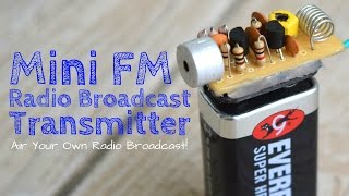
Make a 500m Range

HTML-код
- Опубликовано: 6 июн 2020
- $2/5pcs 2Layer & $5/5pcs 4Layer PCBs: jlcpcb.com
Make sure to visit their website.
Thanks to JLC PCB for sponsor this video
you can watch this video in hindi language,
2nd hindi Channel please #SUBSCRIBE
ruclips.net/channel/UCVQl...
(previous video)DIY #PPM & PWM Drone Transmitter and Receiver_(Step by Step)
• DIY #PPM & PWM Drone T...
####Arduino walkie talkie • Make a 1.5 K.M Range w...
#####5 Watt Long Range Fm Transmitter And Working Principle • 5 Watt Long Range Fm T...
components Purchase Link
1=BC548 NPN Transistor amzn.to/3dG4O8v
2=Crystal XTAL Oscillator amzn.to/3eWbnDV
3= Resistors amzn.to/3cBVjWj
4= mic amzn.to/2Y9WcQO
5=1uF-470uF Electrolytic Capacitor Kit amzn.to/2XCga7F
For more interesting video please donate me on paypal ( amidsttoo@gmail.com) it would be very helpful for me
Download PDF file, Schematic, from here...###
drive.google.com/drive/folder...
FOR MORE INFORMATION
Contact me (Only Sunday)
/ etdiscover
------------------xxxxxxxxxxxxxxxxxxxxxxxxxxxxxxxxxxxxxx---------------


Finally! Someone who explains how fm transmitter works, tysm!
I really enjoy the simplicity and the amanzing stability! Bad stability was the ghost of all my fm transmitters in my all life! Thanks to share it! So i love walkie talkies to play!
oh my god.... I've been watching your channel since your previous walkie talkie..... this one made me subscribe
You are best bro, first e ami bhebe pachhilam na 12MHz crystal er transmitter radio te kivabe catch korbe. Keep it up.awaiting 4 the 2nd part.
Thank you, ❤️😀
Wow you seem to be a genius in this stuff I wish had so much knowledge in electronics thanx 🙏
Mannnnnnnnnn the only perfect tutorial for walkie talkie i have ever seen
I am desperately waiting for part 2
Didn't knew transmitter is so easy to make👌
You seems inspired by Greatscott!
Or he is inspired by you
I don’t think, But this is a Great Guy
I think so.
Ik think so.
Both are providing great tutorials.
I've been searching for a long time
looking for something that I could
represent for electronic school project at integrated life skill subject,,,
thank you, Et Discover,,,,
I think I have discover my new
helper,,,,
🤗🤗🤗🤗
I will wait for the part 2, keep strong 😄👍🏼
Very clean design for having no pc board. This shows what you can do with very little money and lots of imagination.
Waiting for part 2! Thx =)
U ARE ON THE NXT LVL !!!!!! AMAZING VIDEO !!!
Sir this VIDEO was very knowledgeable and inspiring.🙏🙏🙏🙏🙏🙏
Amazing! So simple. :)
Eagerly waiting for the 2nd part , please upload soon ....
it seems that et discover looks like great scott 3
Great Scott & Et Discover is my favorite channel, but I like electronics
Everything is ok.
Just you need a load capacitor on the two sides of the crystal.
22pF would be the best choice...
And also you should use 27Mhz crysral...Because 27Mhz band is licence free in India
Big fan❤
He was transmitting on very low power and as there was no antenna I'll say it's totally legal under personal use.
একদম
Hi does capacitor value has to be exactly 22pF or I can use other values?
You changed my misconception about crystal oscillator.thank you
Welcome
Super!!!
Im waiting for the second part.
Nice! I wish to make a transmitter like this. I'm going to try this!
Next part
Mee 2
Also
@@EtDiscover sir when u will upload next part.
The video gave me a great idea 😁 I will try it and share it with you soon 😌
Great video,, hope to see part 2 very soon
thank you. waiting for next part,
from bangladesh.
Coming soon, welcome
I think you are inspired by great scott well done🔥👏👏
Well explained 👏👏👏👍
Khub informative chilo bro. I love it..... 👍 👍
Thank you
Super bro , it's really awesome
Nice work bro. Looking forward to the 2nd part
Coming soon
You are pro man 💥🔥
Wow! excellent video, explaining about the electronics. Love it. Here is your new friend. stay connected
Mais um inscrito do Brasil. Very Good.
Thanks bro waiting for next part 😍😍😍
❤️
thank you sir. now I am understand how to bias & use crystal ☺
❤️
Very good video, very well explained
Great Video man.
Sir it really works thanks for making this video
Welcome , 😉 Enjoy
This video is helpful to understand 3 type of frequency transmission
FM
SW
AM
Actually those are modulation types 😇
modulation means way of mixing sound with radio wave.
I love the fact that you keep scratching the scale with your screwdriver :D
❤️
Waiting for part 2, thanks
Coming soon
your explanation is good and easy to understand
That,s very nice project we interested to learn more....
You're like a paralell universe great scott
Wow et discover you improved youre mic quality 😍
Thank you,
This video is nice..... Thank you.....
খুব সুন্দর ভিডিও দাদা ...... আমিও ট্রাই করবো ...... পরের পার্ট এর অপেক্ষায় রইলাম
❤️
@@EtDiscover দাদা ক্রিস্টাল টা কত MHz এর দেবো যাতে মোবাইলের রেডিওতে শুনতে পাই।।
Finally, I also found a channel that discusses a very simple transmitter .. I like it bro .. but my question is, because I don't understand radio frequencies. is it possible for the circuit to be a long-distance controller such as drones, rc car and others ... if possible please make a video bro ... I'm waiting ... thanks bro 🙏🙏
Do you find any answers? Can we control toy car,airplain
very impressive and awesome explianation😊
Great project. I saw schematic but not found antenna. In which part of circuit do you connect antenna?
Very good.thanks
It's the best explanation
I love your videos, and I respect the time and effort you put into this work, I do have a difficult time with your accent but I noticed if I slowed down the video, your words come out easier to understand. Most of the time I can understand you because I know electronics very well and can easily figure out your description and tutorial from context alone, I look forward to your next project on the science of electronics and pieces of artwork...I use the noun 'Art' because, with all of your particular projects, there is a strong element of presentation and aesthetics.
Your tutorial is the best
Your are bast explain in every video 🙂
Wow it nice and well explained 😘😘
Great job buddy. Kafi kuch naya sikhne mila. Kya aap ye video Hindi me bna sakte hai. Mujhe apne Students ko ye sikhane ke liye chahiye. Vo abhi itna ache se English bhi nahi jante hai.
Amazing most simplest circuit 😍, hey plz post video how to add rf power amplifier for this💯✌
Please wait for next part
@@EtDiscover im hype for that. see you next time!
Very interesting project... Weldone sir...
Thank you
I like it very much I also trying to make this send very soon
Sir
And your a good teacher
wow thank you! suscribed
❤️
Everything is very good
Very good👍
Wow.... super. I wanted a walkie.-talkie like this. Great work. Waiting impatiently for part2. I am going to make this.😄
Please wait coming soon
@@EtDiscover when
That's a very good looking mustash
Nice project thanks for sharing
Thank you
Bro tnq, I am going to try this project
❤very nice
it is possible to set the FM frequency with a digital circuit such as MCU, I mean digitally change the variables of LC parameters
good idea
Nice my friend 👌
❤️
Great ...
Awesome sir
Nice video. SW and MW are both amplitude modulated. But just changing the crystal to FM range doesn't make it frequency modulated. Don't you also need to change the circuit topology?
I wish he can explain his reasons on this.
no. when you connect audio input straight to the base of the modulating transistor to which base the crystal is connected it does both amplitude and frequency modulation at the same time, at least that's my observations.
@@maalos I just rewatched the video. I'm going to double-down on my assertion that this will NOT work to broadcast FM. If you watch the video, the only place you can hear audio from the transmitter (you hear the whistle of acoustic feedback) is when he has it tuned to an AM band. However, you hear dead silence (or rather noise from touching the circuit, nothing coming from the condenser microphone) when tuned to an FM band. This makes perfect sense since a stable carrier on either AM or FM produces dead silence on the receiver. There is nothing in the circuit that will cause the frequency deviation required to produce FM. What you maybe observing is a deviation of the sidebands when audio frequency changes from the input microphone, but that is NOT FM. Measure the output of that transmitter on a spectrum analyzer and I bet you will see a strong carrier in the center of two smaller sidebands. Even if you can hear something on the receiver when set to FM, it will probably come through very weakly and is a result of AM getting injected into the circuit because you have the transmitter sitting next to the receiver.
EDIT: I watched part 2. He doesn't transmit anything but noisy, crackling, EMF which will show up an all bands and modulations. You don't need a transistor to broadcast that, you just need a wire and a battery! I'm calling BS on this entire project!
Great sir 👍
Amazing
Love you from Bangladesh.
❤️
Very good
You should give the circuit diagram soo it can be understand easily...I am gonna try out this project...waiting for the 2nd part...
Nice video, such a simple looking circuit. Any chance of a circuit diagram for both the transmitter and receiver in the next video please?
Very nice 👍👌😊 bhai
Thanks 🤗
Bhai my channel m.k.r electronic
Good Grow up
Bhai aap surat
Amazing bro
Thank you
Very nice
Love video brother so much 💖💟💖💖
❤️
that intrro slaps!
Nice. Waiting for receiver circuit too. And can we make the crystal variable so thst we can switch channels? In case of interferance?
That’s depending on Crystal, Next part will see the receiver
@@EtDiscover which crystal oscillator you used in FM transmitter.you say higher frequency oscillator but how much does you used for FM frequency?
Love it...
❤️
Watched the walkie talkie and got inspired. Saw this video's thumbnail and said to myself, isko dekho kya Dimaag hoga, wo banda ready made circuit daal diya, then I see its you again.....
Maafi
Subscribed
🙏
What model crystal did you use for fm transmission
Very nicely explained . Can you explain how to recieve a RF signal from this circuit you made.
Please wait for next part video
Sir your video is very nice plz make video on reciever, we are all waiting
nice video i hope you can make an armature radio one day
Wow I need to make this
Are you from america..
I want to make it on pcb for my channel. Provide circuit diagram..
Is it possible to expand the range? If so please make a video displaying how?
Nic work
Nice vid
There are many difference between damped oscillation and resonance.
Resonance frequency is the natural frequency of an oscillating object which used to make undamped oscillation.
Example Swing.
I have no idea what you're talking about but you sound smart so I'll believe you.
nice video!!!!
can you transmit voice out there?
Do you need a power supply?
Yes you can transmit voice
Could you please enable the subtitles? It would help a lot. Good video.