Back to Basics II: Adjustable Current Regulator with the LM317

HTML-код
- Опубликовано: 9 авг 2018
- Back to Basics II: Adjustable Current Regulator with the LM317
LM317 datasheet: www.ti.com/lit/ds/symlink/lm31...
LM317 Voltage Regulator Video: • Back to Basics: LM317 ...
LM317 in my Amazon Store: amzn.to/2AYNNHx
If you are shopping for electronic components, test gear or consumables please consider visiting my Amazon shop @ www.amazon.com/shop/learnelec....
Please check out www.patreon.com/learnelectronics and pledge a dollar if you can. It will go a long way to keeping the channel alive. It costs a bit of money to buy all the items and produce these videos. You help is appriciated.
Or....if you'd like to send a one-time donation you can use this link: paypal.me/learnelectronics
FAQ:
Me: Paul, 49 from USA
Education: United States Navy, University of California at San Diego B.S. E.E., University of Pittsburgh M.S. E.E.
Experience: United States Navy STS, Bayer Intnl Process Engineer, C.C.A.C AP of EE
Current: Retired
Health: BAD (Congestive Heart Failure)
Hobbies: Electronics, flying, amateur radio, music (classic rock)
Low cost, professional PCB's: www.pcbway.com  Наука
Наука


Great application of the LM317!
Thanks Paul i feel a build is at hand great stuff.
I've seen these circuits til I'm blue in the face. However, placing a fixed resistor in parallel with a variable resistor to limit current is really cool. I learned something new. Great video, sir!
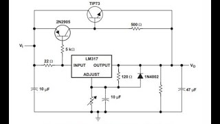
Actually, in the diagram, the 10Ohm resistor is shorted out!
I generally use a LM317L with a 220ohm resistor between A and C and a LED for the load as an easy "no think" way of indicating "output/testpoint high" on the breadboard.
It works from 3.3V and up.
It can easily be put on a 2 pin header and protected by a piece of heatshrink for reuse.
When you teach basic concept use basic things, thats great quote sir
thanks so much for your videos, always a pleasure :)
Great video. Just what I wanted right now😊
OK. I couldn't sleep either so I was up until after 3am. So I really can't think well now but I will think on it. Thanks for showing another side to the LM317!
I am using the LM317 to regulate voltage to my model train smoke heater to maintain nice smoke plumes during various speeds as fan puffs increase cooling air flow. Thanks for sharing. D
Thanks for sharing
Excellent 👌
Cool. Look at where the parallel resistor is drawn. Newbys might be confused by incorrect placement.
I like how you put your additional parralel resistor in your diagram.😄
Regulators arrived today (let’s hear it for Prime!) so I may have time to play with these two concepts over the weekend, thanks Paul... 👍🏻 🧐 🐍
Have fun
Great video I'm a.
Disabled electrician but in the early 80s I worked on video games pinball record machines etc. I'm going to get back into the hobby because of other hobbies I'm going to use at least one if not two server smps what's the best way to add an adjustable voltage and adjustable constant current to the output with volt and amp meter? I'd like your opinion on this..lol I can't sleep either hope you feel better my mom dad brother and best friend had cops thanks for taking time to share the videos
Any chance you could do a video on how to regulate larger currents, like 10A at 40 Volts?
I second that. I presume it's with a transistor of some kind.
Same here. Have an old pyramid linear supply rated for 15A or 20A that I want to convert.
Or 90v 40ampz😂
oh ... how nice at 4.00 you found out that you have a left hand ... great
hi paul, i learn a lot from your videos, thank you! how much amps did you set the load here? what should i do to increase the swing to a max current of about 3 to 5 amps? how would i configure this with a power transistor to achieve higher current limiting?
Adding the cap in parallel stores unused potential and dissipates it back in to the circuit when it falls below a threshold, choosing the right value cap like a .01uF with the right time constant will fill in the noise gap nicely
Well if it's a cap it'd have it's own charge wouldn't it? Up to Xvolts it was rated, usually higher then the input voltage?
Also, if I were to connect a LM317 circuit to a SMPSu (watch out KINDA like other crazy question lol) Could I theoretically draw just up to whatever voltage and amps I was setting the variable voltage to an what the LM/ my circuit demanded? or would connecting that just right to the output bare the full 5v 25amps against the LM and or whatever circuitry I had inline with it since LM317 max is only 1.5 amps..(being hooked up to/running a VERY expensive LD) Or would I be good to power that off that? Or would the weird SMPSU try to limit its draw all together to only 5 volts(which is fine), (12v 18amp is a option to but I'll get alot more heat from volts stepping down.. just worried/confused about the amp thing an the behaviors..) an to 400ma again like usual? Or would me placing the demand unlock the amps the same way I saw when I hooked my DC motor up?
..Is this the same question? I'm done. I'll just wait for your reply an hopefully that helps me get it lol cause it's all obviously related..
Lmao 2 am can't sleep sounds like my problem 🙃
Where would I find a dummy load like the one you are using in this video?
Did the capacitor open up the range because of voltage dtop while charging then increase when discharging
Thanks for your tutorial now I know how to make a current limiter,keep making vids.
How do you set a different voltage? Can you get 2A or 4A?
What is the part name for the potentiometer that you used ?
I have seen a 4.7k pot and a 10k Pot - but does not look like the one in the video !
Nice video and thanks for sharing.
hi, i don't have a breadboard but i have lose wires. is it possible to connect the potentiometer, LM317 and resistor and power source directly with each other without breadboard?
Ok, very nice. I did not realize it would be this simple. I built an ATX power supply with voltage selector and volt meter. One terminal is constant 12V. Another terminal can be switched to the 3 diff. outputs. I should take the 12V off that terminal, guess why?
Anyhow. I want to charge various rechargeable batteries with it and need a currant regulator.
battries can range from 1.5 to 12V. I just wonder if this circuit will cover all the mA ranges I will encounter?
This looks promising thanks; thumbs up.
👍👏
Could you use the output to drive a MOSFET or something if you wanted to limit a large current?
This circuit is meant to regulate current, but a mosfet is a voltage controlled device.
You can use this circuit to regulate the base current of a bjt
But if you do that the transistor will saturate during constant current operation and dissapate a lot of heat which is not ideal
I was wondering if you can do an adjustable current source with a TL 431?
Thanks in advance Paul, you are doing a great service.
Yes you can
Make it so much easier. Say, what is the name of that nifty power supply you have? Thx for your effort.
I believe it is because of low ESR of the capacitor. Low ESR equals more current capability.
Using the last two videos, I looks like it would be possible to build a regulated voltage supply that is current limited by putting the two circuits together in a series circuit. Is this correct? I guess I now have to get some LM317's to play with!!! I need more room!!!!
Yes I’ve done it and it works well.
Problem here is that the resistor needs to pass the current to your load.
Very few variable resistors can take that. Remember: P=I^2*R
@@DeeegerD what current output , 100mA :)
Isn't the resistor you added shorted out or is it in place of the short that's making the pot into a variable resistor? Hope that makes sense Paul!
dan blankenship thanks Dan. I'm not nitpicking just clearing up the exact location as complete beginners may copy the circuit without question and wonder why they're getting different results!
I would assume that even the capacitor has its own resistance value...if so that would account for the extra Amp potential...
Due to the capacitors ESR .
yup
can you explain more plz?
wait how the heck it didnt bypass the variableR was it because the resistance was lower?
Hello, very nice video ! i did the same, i used 1.5 Ohm to have an output of max 1A, but when i plug a load to my 12v lamp bulb, the voltage drops to 4v, is it normal ? many thanks.
Depends on few things. It will drop at least 1.25V. at what point u measured 4V?
Got similar problem. But I never got more than 100mA so even a tiny LED reduce the voltage a lot. I wonder if it depends on what model (x) of LM317x it is.
Just for the fun of it, put a led and a resistor as your load. Set the current at 15ma for instance. Afterwards, vary your input voltage a bit, up and/or down, just to show how the regulator will do its best to keep the current constant. You might consider putting a voltmeter across the led, showing the impact. By the way, I noticed two little "hoopsies" in your clip. First one was around 04:10 when you said "7 ohms swing" instead of "7 milliamps swing". The second one was aound the 05:03 mark when you drawn the resistor on your schematic. I think you put it on the wrong side because as shown, it is shorted across the A & B terminals. I understand that our minds aren't always as sharp as we would like them to be in the middle of the night. Been there, done that too ! For the effect of the cap on the input I'm not sure. I was under the impression it was mainly for filtering/stability purposes but now we can see it has a another side effect. As per my understanding of the LM317, I'd be lead to believe that the capacitor could potentially be adding a small variation of the current on the ADJ pin which in turns is amplified by the internal Darlington transistor, thus slightly increasing the output voltage leading to a wider current range. It's almost like lottery, we simply hope to have the proper combination.
blog.capitalogix.com/.a/6a00e5502e47b288330192ab34ad86970d-600wi
learnelectronics So this is where the energy comes from ? 😷
learnelectronics You got it wrong Paul, goo.gl/images/sx9vt5
Yup lol
Thank you paul for your help and a lot of fun .
Hello if anyone have time please help me. How Can i use for example 10k adjustable potentiometer to act as 200R ? A mean i drive LED from 18650 battery with cca 270R using resistor... But i need IT to be regulable but resistors in size i need i see only like 10K and so.... So in final i will have 200R smallest and 400R highest resistance using 10K regulable resistor...
First you call the swing millamps, then ohms, then volts. BTW, there's not much you can power off a 1/4 watt pot.
hello it is voltage regulator not current !? it means you can not have a 12v with 200ma of current
Hello. I am a total novice. I have soldered, stick welded, and wired houses, so, I do have a healthy respect for electricity, just f.y.i. but not too much knowledge. I have a purely selfish request, but maybe it will be of benefit to many just by way of reminder. And , also, it feels good to help others. I want to make a simple 1000 watt (or maybe 1500 watt) adjustable voltage regulator. I think I want to make 2-3. I want to control heating elements without use of inconsistent mechanical thermostat; and I also plan on making a peltier freezer/fridge ( or maybe just ice maker). I have limited funds. I have soldering iron and elec solder. Any help is greatly appreciated.
i have a feeling like the lm317 is entirely redundant here, if you have a constant voltage, you can just use a pot to vary the resistance and with that the current that flows
with a simple, if the voltage changes, so will the current. with the lm317, the current will maintain its vlaue despite changes in the voltage.
ah i see
You only got 100mA. Is that the limit of the LM317T?
I'm trying to get around 1A, but also only get around 100mA.
Limit is 1.5A
@@kekwnet have you manage to get anywhere near 1.5A?
Damn coffee